types of controllers to provide custom power of requisite quality are ... mode if capacitor VARs are provided for self excitation and ..... Power App. and Sys., Vol.
CAPACITIVE VAR CONTROLLERS FOR INDUCTION GENERATORS FOR AUTONOMOUS POWER GENERATION S.S. Murthy and Bhim Singh Department of Electrical Engineering Indian Institute of Technology New Delhi * 110016, India variation of Capacitor VAR needed for the SEIG corresponding to the primemover speed and the connected output load. This paper presents different controllers for different possible applications based on their experience in developing such systems over the years.
Abstract. Self Excited Induction Generators (SEIG) require Controllable Capacitive VARs to magnetise the machines and compensate the demagnetising effect of loads. Different types of controllers to provide custom power of requisite quality are discussed for different types of prime movers such as oil engines, Hydro turbine and wind/wave turbines. Schemes involve self regularity devices, power electronic controllers, automatic regulating and electronic switching. The criteria of design of controller with each primemover are discussed. For autonomous power generation independent of the grid suitable schemes either with single unit or hybrid modes involving more than one energy source are described.
The paper also- presents general methodology and philosophy to be followed in the design of such controllers. Typical results on some units are presented as illustrations. At the design stage it is important to estimate the Capacitive VAR requirement for the given range of speed and load at resistive, partly inductive and dynamic loads. The paper presents a methodology for the same and some empirical thumb rules to help the designers.
1.
INTRODUCTION Energy crisis has given a philip to the exploitation of Non Conventional/ Renewable energy sources. Often the inability of the utilities to supply uninterrupted custom power has lead to users resorting to standby/autonomous power generation. Continuous improvements in the energy conversion system in such usage are being attempted. ' Reliable* simple and efficient generator with a suitable control mechanism, form an important component of such systems. Induction generators are conceived to be appropriate due to their rugged/robust construction and minimum weight per unit power. They are used almost universally for wind energy systems feeding to the local grid. Recents an induction generator system driven by wave energy has been installed and extensively experimented in a site near Trivandrum in Southern India.
2.
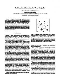
VAR REQUIREMENT OF INDUCTION GENERATOR IN STAND ALONE MODE An induction generator can operate in stand alone mode if capacitor VARs are provided for self excitation and to compensate the inductive components of loads. By controlling these VARs required power quantity may be obtained. The basic scheme is shown in Fig. 1. In simple terms the p.u. is speed v decides the generated p.u. frequency, F while the capacitor VAR decides the voltage VL across the load. With varying prime mover speed and load, VAR has to be varied to give the desired voltage. The scheme of Fig. 1. can be modelled through a steady state equivalent circuit of Fig. 2 with usual notation [4,13].
While Grid Connected Induction Generators have found wide applications in the field their use for autonomous power generation either in hybrid or self excited independent mode is presently under intense investigation since the technologies have yet to fully mature for field installation to meet the consumer requirement. Analysis, design and control aspects of self excited induction generators (SEIG) are dealt in several published papers [1-14], A crucial aspect in this area is the development of appropriate control mechanism to achieve described output in terms of voltage, frequency and waveform at varying loads with different types of primemovers. This is an area needing intense research and development efforts aimed at evolving an appropriate SEIG unit that can be manufactured and marketed. Basic function of these controllers is-to effect
0-7803-2795-0
Primt mover
Fig. 1. SEIG system
679
Ind. CapQCJtor
Load
For designing controllers, the capacitor VAR requirement to get the desired voltage levels must be known. From the equivalent circuit of Fig. 2, a method to predict the performance of SEIG for the given speed, load, PF and capacitance using Newton-Raphson method has been repeated[13]. Apart from fixed machine parameters it uses the magnetisation caracteristics. An interative procedure yields capacitor value for the given voltage. The magnetisation curve can be obtained (a) design data (b) test and (c) fitted curve from design through an equation using test or design data. The characteristics for a 3:7 kW, 50Hz,, 4-pole, 415V, 7.6 A, 3-ph delta connected induction machines are given in Fig. 3. The p.u measured parameters of the machines are: Rs = 0.61, Rr = 0.053, x^ = x,, = 0.087, ^ (unsaturated) = 2.85,. R
The p.u. VAR requirement to give rated voltage at different PF at 1.0 speed is given in Fig. 4, with machine rating as base. The VAR is typically 0.7 p.u. at no load increasing to about 1.2 p.u. on full load (l.OPF) which further increases to about 2.0 p.u. at 0.8PF. 2 22.1 2.03
19 _
s/F
R L /F Rr/F-V
0 0.1 0.2 0.3 0.4 0.5 0.6 0 7 0.8 0.9 1.0 1.1 1.2 1.3 U 1.5 1.6 output power,p.u. (3.7kw machine )
Fig. 2. Steady State equivalent circuit.
Fig. 4. VAR requirement of 3.7 kw machine at constant speed a = 1.0 pF frequency b = 0.9 pF o o o experimental points c = 0.8 pF . . from measured magnetisation curve (l.OpF) - capacitor KVAR _x__ , from linearised magnetisation curve
b
X 1.1
10 0 09
I
y^ \
OS 0.7
3
d
4
t 0.6 0.5 O.i
f
-
0. 0. 0
\
J
.2-
2.0 • •
•
\f/.I
2.0
1.0
3 1.5 a,
• 3.0
S 0.1
computed x x experimental
kVAr -•*•-• computed o o experimental
2.5
r
¥ *
• 1
0
g
v". •\ •
0.2
0
3 0.-4 I m p u.
0
5
0.6
0.7
1.0
0.8
Fig. 3. Magnetisation characteristics of a 3.7 kw, 4 pole, 50 Hz machine a Vg/F, Vv Im b V F , Vt) xm xxx design points from fitted curve fitted curve (design points) ® ® ® design points O O O expt. points • • • from expt. points fitted curve (expt. points) fitted curve (expt. points)
0.5
0
0.3
1.0 P out
1.5 p.u.
2.0
2.5
Fig. 5. VAR requirement at different speeds
3.0.
2*5
1.5
voltage is given in Fig. 7. It is interesting to note that at rated current, the power varies widely with speed. The performance figures for a range of motors used as SEIG are given in Table. I. VAR variation from no load to fill load at 1.0 p.u. speed are given which can help controller design.
2.0
3.
a.o
3.1
VAR Controller with different primemover with typical results. Near Constant Speed Primemover such as oil
0.5
0
0-5
1 1.5
1.0 P
L 2.0
2.5
Here the speed drop from no load to full load may go upto 5% which causes drop in frequency, which is more pronounced in induction generator compared to synchronous generator. An increase in output electrical power is automatically provided by the engine through increased input in the form of increased fuel consumption. Thus the power balance is automatic. Here capacitor VAR has to increase with load (see Fig. 4). Several schemes are possible.
3.0
out
Fig. 6. VAR requirement when
V .
—
is constant
The additional VAR at lagging PF load is to compensate for inductive component of load. The controller must effect these changes to results in the voltage at varying loads. Here the frequency variation is not considered as it is negligible. At varying speeds VAR demand varies widely as shown in Fig. 5 for a 3.7 kW 230V, 14.2 A, 4-pole, 60Hz star connected machine. Here rated these values are taken as base, so that rated power is nearly 3.0 p.u.). At varying primemovqp speed a criterion of constant flux can be used such that —- = constant. Corresponding capacitor requirement is given in Fig. 6. Variation of machine current at constant terminal
3.1.1 Series .Capacitor Scheme: Here a capacitor of suitable value is connected in series with the load such that capacitive VAR increases into load. Schemes and results for 1-phase and 3-phase system are presented in two comparison papers by the author. 3.1.2
Saturable Core Reactor: An appropriately designed saturable core reactor, Fig. 8 connected across SEIG terminals will clip the voltage at no load and reduce the VAR. Here the connected shunt capacitor
computed x x experimental points computed
1.75
o o experimental
From induction generator
-1.2
Fig. 8. Saturable Core reactor
0
0.5
1.0
1.5 2.0 2.5 3.0 Pout..P.u. Fig. 7. Variation of machine current and frequency with load.
Fig. 9. Black diagram of SEIG with saturable reactor
681
corresponds to highest load at lagging PF. Fig. 9, shows the schematic of a voltage regulator into saturable core reactor.
angle.
3.13
Power Electric Controller While the above two schemes are simple, use passive elements and provide self regulating features to same extent more accurate VAR controller can be designed using controllable power devices.
100 90 CO
(a)
Switched capacitor scheme : From Fig. 4 the connected capacitance has to change from a minimum value C min at no load to a maximum value Cmax at full load (lagging PF). A switched capacitor scheme shown in Fig. 10 can be employed with a fixed capacitor Cx in parallel with binary weighted. Capacitors
70
^ SO
a* .Machine current
| 50
b*. Capacitor current , c : Load current
= 10
d: Load vottao* t:
Ellicicncy
.Terminal voltage ( p u ) Calculated :.-_ Measured
Machine
Capacitor bank
Load
Fig.10. Switched Capacitor scheme C, 2C, 4C whose total value is equal to ( C ^ - C min ), such that a variation from Cx to Cj + 7C in steps pf C can be x obtained through a proper sequence of switching. Switches 1, 2, 3 can be power electronic devices or electro mechanical contactors. A contactor based electronic scheme has been developed by the authors where the load current is taken as a feed back signal and appropriate switching effected using a look up table to give the required voltage. The scheme maintains the voltage in an acceptable band. Although fine control is not possible it has the advantage of distortion free wave forms. Typical test results using the scheme on the 3.7 kW machine is given in Fig. 11. voltage is maintained within the band 440 - 400 V. The readings were taken by gradually increasing the load so that the voltage is automatically adjusted by the switching mechanism. The generatqr was loaded upto its rated current. Static VAR Scheme Fig. 12 shows a per phase schematic of the static VAR scheme. The fixed capacitor C corresponds to full load and the current in the inductor L is varied by a solid state control scheme. A normal 6-pulse converter can be used wherein the input impedance is varied by varying the firing
n ft
0 0
0-2
O.i 0.6 08 -10 Power output(p.u)
1-2
Fig.ll. Performance characteristics with switched capacitor scheme.
b)
I
.
Machine
Capacitor Variable inductor
Fig.12. Variable inductor scheme
682
Fig.13 shows such a circuit which has a resistance R^ in series with an inductance Ldc on the d.c side, which is the generalised version of the two schemes one with only inductor and the other with only resistor reported earlier [3, 6]: With only a resistor, firing angle has to be varied in the approximate range 60 deg. - 120 deg. to get the required range of lagging VAR. But this is associated with losses and effective impedance at the a.c. terminals will have a sizable resistive component. This may be a blessing in disguise if used in micro hydel applications as it partly acts as a load controler at light loads. With only an inductor L firing angle has to be varied in the approximate range 85-90 deg., which varis I^ from a maximum value to zero. The inductor is bulky and expensive. A combination of R^ and La can be tried, which minimises the total cost of the control circuit with a power loss within limits, and provides better controllability. Such a' control scheme has been developed and typical test results are given in Fig.l4(a) for 3.7 kW machine. Currents 1^ and 1^ of the bridge decreases with load to reduce inductive VAR. This scheme is costlier than the switched capacitor arrangement.
.«
From
machine
fTl"
Fig.l4(b). Circuit schematic of control Scheme with inductor on dc side The circuit systematics of control circuit of the SVS using an inductor and resistor on dc side are shown in Fig. 14(b) respectively. Due to thysistor switching this scheme introduces harmonics in currents and voltages. Harmonic components with load for a 3.7 kw 230 V, 60Hz machine is shown in Fig. 15. Another method to obtain variable inductor is to have thyristor controlled inductors whose schematic is shown in Fig. 16.
°~
I f Fig.13. Static VAR scheme with controlled rectifier »rv
no" ioo"so°-
o.o
70'-
0,5
1.0
Fig.15. Harmonic components in SVS.
to' 50'
30"- S3
Fig.l4(a).
1.5
c: Machint curr«nl.lf4 b' Fifing angle*
Characteristics with Static VAR scheme at fixed voltage, speed and PF, with R-L load on dc. 683
Fig.16. Thyrister controlled inductor
out
2.0 pu
2.5
4.
Constant Power Prime mover - Small Hydro Turbine Uncontrolled Small Hydro tin-bines operate at near constant power at constant Head and discharge of water. Output power of SEIG should also be constant independent of consumer load. A normal procedure is to use a load controller which feeds a dump load such that the total power output of consumer load and dump load remains constant Fig. 17 shows a schematic of
dc load
SEIG Terminal
ConUoiler rectifier
Fig.20. Load controller with controlled rectifier 3 Phase
Copacilof
i
Control unit
Fig.17. Schematic of microhydel unit with SEIG. such a unit. The load controller can be (a) binary weighted resistor Fig.18 where output power is
L_—_:_....„ Uncontrolled Bridge Rectifier
Fig.21. Uncontrolled rectifier with chopper.
Fig. 18. Load controller with switched resistor controlled through proper switching (b) a 3-phase resistor bank whose power is controlled by adjusting the firing angle of in line back to back through Fig. 19(c) a resistor fed by a controlled rectifier Fig. 20(d) uncontrolled rectifier feeding a resistance through a chopper whose duty cycle is controlled (Fig. 21).
Fixed load
Fig. 19. Thysistor controlled resistor
Detailed discussion on relative merits and demerits of the above schemes is beyond the scope of this paper. Scheme (a) though appears simple and distortion free has the problem of reliability of switches after several operation. Since small hydro schemes are located in remote areas the controller must be reliable and maintenance free. With the advent of high power MOSFETs & IGBT's the chopper scheme of Fig. 21 appears to be a winner with only one device to control. 5.
Variable speed primemover-wind turbine. Autonomous power generation with variable speed prime mover such as wind turbine has been found to be very complicated and almost unviable with a single source although academic exercises are being carried out. Wind battery system is the nearest to reality. Power from wind varies as cube of wind speed and the rotational speed of the wind turbine has a relation to this power input. It must be realised that rotational speed has no direct relation with wind speed as it is dependent on wind turbine characteristics and connected load. Several types of controllers can be concerned. Fig. 22 shows the systematic of SEIG inter AC-DC link. Maintaining desired voltage and frequency at the load is a herculian task. Fig. 23 shows the schematic of a wind battery system.
684
Hybrid system such as wind-diesel arrangement is an attractive option with diesei engine driven generator maintaining the load voltage and providing the VAR to wind driven induction generator. [15-17]. A dump load is essential such that the control system must provide for automatic power balance equating sum of input power from diesei & wind to the sum of output power fed to consumer load and dump load,
2.
5.
3.
has to find field acceptance. At present the technology is mainly in laboratory stage. REFERENCES: 1. Michael B. brennen, A. Abbondanti, "Static Exciters for induction generators", IEEE Trans, on Industry Applications, Vol. 13, No. 5, pp. 422-28, Sept./Oct. 1977.
Oscillating power primemovers - Wave turbine. One of the most complicated engineering challenges in this area would be to develop a stand-alone power generating unit with turbines actuated by sea-waves [18]. The wells turbine actuated by waves produces oscillating power input to the generator. Only a hybrid system can be conceived. The schematic of a proposed Wave-diesel system is given in Fig 24. The output of a wave turbine driven capacitor excited inductor generator is rectified and inverted through a line commutated invertor wherein the a.c. line is maintained by the diesei driven synchronous generator. The control system must provide power balance and power quality.
4.
5.
6.
A.K. Tandon, S.S. Murthy and G.J. Berg, "Steady state analysis of capacitor excited induction generators", IEEE Trans, on Power App. and Sys., Vol. PAS-103, No., pp. 612-618, Mar. 1984.
7.
N.H. Malik and S.E. Haque, "steady state analysis and performance of an isolated self-excited induction generator", IEEE Trans, on Energy Conversion, Vol. EC-1, No.3, pp. 134. 139,1986.
CONCLUSION : Different possible VAR controllers for induction generators driven by different type of prime movers are presented and reviewed. While some of the schemes have been developed and tested others are conceptualised for practical realisation. Typical results with some of the schemes are presented as illustrations. Typical VAR requirements of SEIG with varying load and speed are graphically presented in p.u. to guide the designers of control schemes. At 1.0 p.u. speed, capacitive VAR range from 0.7 p.u. to 2 p.u. appears realistic. Speed is a sensitive parameter in SEIG. With constant speed primemovers the capacitive, magnetic or power electronic VAR controller can be realised. With constant power primemovers such as hydro turbine, load controller is essential by employing in using a dump load. Controller with wind turbine is more complicated due to randomly changing wind speed and power. Wind-battery or wind -diesei may only be considered for which practically viable controllers need to be developed. Controllers required for an oscillatory power primemover such as wave turbine is more involved, although the power input is not as random as the wind power. Wave-diesel is one,idea which needs to be pursued. A comprehensive list of controllers presented in this paper, needs to be pursued for practical realisation if SEIG
J. Arrillaga, D.B. Watson, "Static Power conversion from SEIG", Proc. IEE, Vol. 125, No. 8, pp.743-746, Aug. 1978. R.K. Miskra, Bhim Singh and M.K.Vasantha, "Voltage regulator for an isolated self-excited cage induction generator", Jr. of Electric Power System Research, 24, pp. 75-83, 1992. S.S. Murthy, O.P. Malik and S.K. Tandon, "Analysis of self Excited Induction Generators", Proc. IEE, Vol. 129, Pt. C, No. 6, pp. 260-265, Nov. 1982. J.M. Elder, J.T. Boys and J.L. Woodward, "The process of self excitation in induction generators", IEEE Trans, on Power App. and Sys., Vol. PAS-103, No. 3, pp. 612-618, Mar. 1984.
8.
C. Grathan, D. Sutanto and B. Mismail, "Steady state and transient analysis of SEIG", IEE Proc. Pt. B, Vol. 136, No.2, pp. 61-69, Mar. 1989. 9. S.P. Singh, Bhim Singh and M.P. Jain, "Performance and optimum utilization of a cage machine as capacitor excited induction generator", IEEE Trans, on Energy Conversion, Vol. 5, No. 5, pp. 679-685, Dec. 1990. 10. L.Shridhar, Bhim Singh and C.S. Jha, "Analysis of self excited induction generator feeding induction motor", IEEE Trans, on Energy Conversion, Vol. 9, No. 2, pp. 390-396, June 1994. 11. A.H. Al-Bahrani and N.H. Malik, "Voltage control of parallel operated self excited induction generators", IEEE Trans, on Energy Conservation, Vol. 8, No. 2, pp. 236-242, June 1993. .12. S.S Murthy, H.S. Nagraj and A. Kuriyan, "Design Based Computation Procedure for Performance Prediction and Analysis of Self Excited Induction Generators using Motor Design Packages", Proc. IEE, Vol. 135, pt.B, pp 8-16, January 1988. 13. O.P. Malik, D. Divan, S.S. Murthy, T. Grant and P. Walsh, "Solid State Voltage Regulator for Self Excited Induction Generator', IEEE Industrial and Commercial Power Systems, Conference, Milwaukee, May 1993. 14. HAagaard Madsen, P. Lundsager: "The Wind/Diesel Development Programme at Ris$ National Laboratory - Status
685
1985". Proc. Wind-power ' 85, San Francisco, USA, October 1985. Also Ris^-M-2537. 15. N.H.Lipman, JA.N. de Bonte, P. Lundsager: "Review of Wind/Diesel Integration: Operating Strategies and Economic Prospects". Proc. EWEC 86, Rome, Italy, October 1986.
( ~- 1
3PHASE , AC LOAD C«| GRID
* / *
V J
VARIABLE SPEED PRIME MOVER
16. J. Linders, L. Holmblad, B. Andersson: "The Autonomous Wind/Diesel System at Chalmers Technical University". Proc. EWEC 86, Rome, Italy, October 1986. 17. P.V. Linders and S.S. Murthy: "Explying Wave Energy for Electidty" Indian
CAGE INDUCTION GENERATOR
RECTIFIER
INVERIER
-it CAPACITOR
TURBINE
Fig.22. SEIG with AC-DC link.
BANK
INOUCTION MACHINE
EXCITOR, RECTIFIER ANO CONTROLL£R
INVERTOR ir n c u BATlilY UNIT rig.^3^ Scaematic of a wind battery system
Load bus
. Separate excitation
Diesel engine
\
/ * ~ \ V
"V^'y
»—rwpnr>-\
Fig.24. Schematic of a wave-diesel scheme.
686
[Excitation control ]