Advanced Biomedical Engineering 5: 142–148, 2016.
Original Paper
DOI:10.14326/abe.5.142
Cell Patterning Method Using Resonance Vibration of a Metallic Cell Cultivation Substrate Chikahiro IMASHIRO,* Yuta KURASHINA,* Kenjiro TAKEMURA**, #
Abstract Spatial control of cell position is essential for numerous studies in tissue engineering, such as generation of linearly patterned muscle tissues, radially patterned liver lobule tissues, and circularly formed anal sphincter. This study proposes a novel method capable of patterning cells in a certain shape on a cell cultivation substrate. The concept is to pattern cells along the nodal position of resonance vibration on a cell cultivation substrate. Note that there are numerous resonance vibrations with different nodal patterns. In this study, we constructed a cell cultivation device consisting of a metallic cell cultivation substrate that can be excited to generate resonance vibration using a piezoelectric ceramic disk glued to the back of the substrate. In this study, we generated resonance vibration with a cross-circle nodal pattern. The cultivation substrate was a ø40 mm × 1 mm stainless steel plate, and the resonance frequency of the vibration was 21.4 kHz. Using the device, we conducted cell patterning experiments employing calf chondrocytes using various vibration amplitudes (1.0, 1.5, and 2.0 µmp-p). Cells were cultured for 2 hours. After the experiment, the cell density distribution on the substrate was measured by staining viable cells with calcein. Additionally, we confirmed the viability of the patterned cells after exposure to acoustic pressure produced by the resonance vibration by counting the number of cells attached to the substrate. Viable cells were successfully patterned along the nodal position when the vibration amplitude was 1.5 µmp-p. The number of cells attached to the substrate was 99.2% of that without vibration. Conversely, when the amplitude was 1.0 µmp-p, the cells were not patterned. The acoustic pressure produced by 1.0-µmp-p vibration was not large enough to move cells. Similarly, the cells could not be patterned when the amplitude was 2.0 µmp-p. In this case, flow of the culture medium induced by the high acoustic pressure probably prevented the cells from patterning. In conclusion, cells can be patterned along the nodal position of resonance vibration generated with an appropriate vibration amplitude. We believe that this method has great potential for use in tissue engineering. Keywords: cell patterning, resonance vibration, ultrasound, regenerative medicine, tissue engineering. Adv Biomed Eng. 5: pp. 142–148, 2016.
1. Introduction Spatial control of cell position is crucial for numerous biological studies and applications in tissue engineering and regenerative medicine [1], such as generation of linearly arranged muscle tissues [2], radially arranged liver lobule tissues [3], and circularly formed anal sphincter. Developing such organs would expand the possibility of tissue engineering. Because cell patterning techniques facilitate a wide variety of applications as mentioned above, a number of studies in various disciplines such as microelectromechanical (MEMS) systems, dielectrophoresis and ultrasonics have been reported [4–7]. Lam et al. [2] cultured myoblasts on a silicone substrate with a wave-patterned surface to form myotubes. Cells were aligned according to the wave pattern. However, the cellular arrangement is limited to the wave pattern formed on a silicone substrate with This study was presented at the Symposium on Biomedical Engineering 2016, Asahikawa, September, 2016. Received on July 22, 2016; revised on September 23, 2016; accepted on November 20, 2016. *
School of Science for Open and Environmental Systems, Graduate School of Science and Technology, Keio University, Yokohama, Japan.
**
Department of Mechanical Engineering, Faculty of Science and Technology, Keio University, Yokohama, Japan.
#
3–14–1 Hiyoshi, Kohoku-ku, Yokohama 223–8522, Japan. E-mail:
[email protected]
MEMS technology. Ho et al. [3] arranged liver sinusoid endothelial cells in a radiating pattern using dielectrophoresis to reproduce the morphology of liver lobule. However, the pattern of cells is limited to the shape of the electrode. One of the most widely known cell patterning methods is surface modification [8]. Cells adhere readily to hydrophilic surfaces, but not to hydrophobic surfaces [9]. Cells can be patterned using a hydrophilic-hydrophobic pattern on a cell cultivation substrate [4]. Using these techniques, cells can be patterned in different shapes. However, a major problem is that a specific device can only arrange cells in a certain pattern. Acoustic tweezers are one of the most promising techniques for directly patterning cells, which can selectively arrange cells in several patterns using one device [7]. When an acoustic pressure wave is applied to a cell cultivation chamber, it generates a pressure distribution pattern with constant positions of nodes and antinodes. Cells are then gathered to the node positions of the wave, where the acoustic pressure is relatively low. This technique is considered to be a noninvasive and high-resolution cell patterning method. However, the possible cell allocation patterns are so far limited to dots, lines, and mesh. To generate more useful shapes such as circular and radiating shapes noninvasively using one device, we focused on the resonance vibration modes of the cell cultivation substrate itself. As the resonance vibration mode of a cell cultivation substrate is generated, cells may be gathered to the node position of the vibration mode, because the substrate hardly vibrates at the node position but mainly vibrates at the antinode position [10]. An attrac-
Chikahiro IMASHIRO, et al: Cell Patterning Method Using Resonance Vibration of a Metallic Cell Cultivation Substrate
(143)
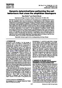
Fig. 1 Eigenvalue analysis (ANSYS 15.0). Colored bar indicates outof-plane displacement normalized to the maximum amplitude (vibration frequency, 26.9 kHz).
tive feature is that a plate or a substrate has an infinite number of resonance vibration modes with various node shapes [11]. This concept is based on Chladni figure formation [12] of particles scattered on a plate and trapped to the node positions of resonance vibration generated on the plate. Ultimately, we can align cells to a variety of node shapes such as linear, circle, and radiating shapes, by selectively generating different vibration modes in a cell cultivation substrate, although more complicated substrate design may be required. We have reported the basic concept of this cell patterning method at an international conference [13]. In our previous report, we patterned cells in a circular shape. The present report demonstrates in detail the cell patterning method and the relationship between the distributions of vibration amplitude and cell density on the cultivation substrate. In this study, the resonance vibration mode of the cell cultivation substrate had a cross-circle nodal pattern (Fig. 1), which was different from the resonance vibration mode with a single nodal circle used in our previous study [13]. Together with our previous report, this study may reveal the efficiency of selectively generating resonance vibrations in a cultivation substrate to arrange cells in various shapes.
2. Design and fabrication Figure 2 shows the cell cultivation device. The device consisted of a metallic cultivation substrate capable of generating a resonance vibration mode with cross-circle nodal pattern (Fig. 1), an acrylic cover, acrylic base, silicone rubber wall, and silicone rubber base, assembled with stainless steel bolts and nuts. The cultivation substrate was sandwiched between the silicone rubber wall and silicone rubber base. The inner diameter of the silicone rubber wall corresponded to that of the nodal circle, so that the vibration amplitude would not be damped significantly by the silicone rubber wall. The cultivation chamber was 36 mm in diameter and 5 mm in depth. A detailed explanation of the substrate design and the method to generate resonance vibration effectively are given in Supplement S1. Using this resonance vibration mode, cells seeded on the cultivation substrate may be trapped to the nodal cross position that can be considered as the simplest form of radiating shape (Fig. 3). We evaluated the vibration performance of the cell cultivation device. The resonance vibration mode with the cross-circle nodal pattern was generated on the cultivation substrate by applying an AC voltage to the piezoelectric ceramic disk. The vibration
Fig. 2 Cell cultivation device. (a) Exploded view. (b) Bottom view.
Fig. 3 Cell manipulation using resonance vibration. (a) Node shape. (b) Shape of patterned cells.
velocity of the cultivation substrate was measured using a laser Doppler vibrometer (LV-1800, ONO SOKKI, Japan). To mimic the cultivation condition during measurement, the cell cultivation chamber was filled with 2 mL of culture solution. Figure 4 shows the relationship between the driving frequency and maximum amplitude with a driving voltage of 30 Vp-p. Note that the amplitude was normalized to the maximum value. Based on this result, we measured the amplitude distribution on the cell cultivation substrate with a driving voltage of 30 Vp-p and driving frequency of 21.4 kHz. The amplitude distribution was measured along the antinode/node directions as shown in Fig. 5. Figure 6 compares the measured and analyzed amplitude distributions. Note that the vibration amplitude was normalized to the maximum amplitude. Figure 6 suggests that the resonance vibration mode with a cross-circle nodal pattern was successfully generated on the cell cultivation substrate. The correlation coefficients between the measured and analyzed data were 0.93 for the antinode direction and 0.86 for the node direction.
3. Experimental methods of cell patterning We used calf chondrocytes in this study. Cell preparation is ex-
(144)
Advanced Biomedical Engineering. Vol. 5, 2016.
study [10]. Cell patterning experiments were performed as follows.
Fig. 4 Relationship between driving frequency and normalized vibration amplitude (voltage, 30 Vp-p). The amplitude is in out-ofplane direction and normalized to the maximum value at resonance.
3.1 Effect of vibration amplitude on cell distribution Cells were seeded into the cultivation chamber and incubated at 37 C with 5% CO2 for 3 minutes. The number of seeded cells was 5.0 × 10⁴ (2.5 × 10⁴ cells/mL), which was less than confluent on the cell cultivation substrate to provide enough space for the cells to move. The resonance vibration with a cross-circle nodal pattern was generated on the cultivation substrate for 2 hours to manipulate the cells. The frequency was set at 21.4 kHz, corresponding to the resonance frequency of the vibration mode. After incubation for 2 hours, viable cells remaining on the substrate were stained with calcein (C0875, Sigma-Aldrich), and the cell density was measured at each location along the antinode/ node directions shown in Fig. 5. Before staining, the medium was removed from the cell cultivation chamber and the remaining cells were washed twice with phosphate-buffered saline (PBS). 3.2 Effect of vibration amplitude on cell adhesion After 2 hours of incubation, we counted the number of cells floating in the medium and the number cells attached to the cell cultivation substrate to confirm cell viability after exposure to the resonance vibration. The cells floating in the medium were counted using a hemocytometer after the medium was removed from the chamber. After removal of the medium, the attached cells were washed twice with PBS. Then, the attached cells were detached from the substrate by trypsinization, and the cell number was counted using a hemocytometer.
Fig. 5 Directions for amplitude measurement, antinode direction, and node direction.
Fig. 6 Amplitude distributions obtained by piezoelectric structural analysis.
plained in Supplement S2. Cells were patterned on the substrate using resonance vibration. The maximum amplitude of the resonance vibration was set at 1.0, 1.5, and 2.0 µmp-p by adjusting the driving voltage. This amplitude setting was based on our previous
4. Results and discussion Figure 7 shows the cell distributions at various vibration amplitudes. The cell density was normalized to the average cell density obtained without vibration. Note that cell density could not be measured up to 16 mm from the center because of the edge of the silicone rubber wall. Therefore, the measurement range was up to 12 mm. Figure 7 shows that when the maximum amplitude of the resonance vibration was 1.0 or 2.0 µmp-p, the cell distribution showed no clear relationship with the amplitude distribution. At the lower amplitude (1.0 µmp-p), the cells were not effectively manipulated because the acoustic pressure was not high enough to manipulate the cells. At the higher amplitude (2.0 µmp-p), the cells also could not be patterned, because a strong flow of the medium was induced by the vibration [7, 14]. This acoustic streaming flow prevented the cells from coming in contact with the substrate. However, at the appropriate vibration amplitude (1.5 µmp-p), more cells were observed near the node position than near the antinode position. The stained cells exposed to the resonance vibration at a maximum amplitude of 1.5 µmp-p are shown in Fig. 8. Few cells were found near the antinode position [Fig. 8(a-3, a-4)]. Additionally, a boundary between the cell-attaching and -detaching areas was observed [Fig. 8(a-3)]. Figure 9 shows the relationship between normalized cell density and vibration amplitude for resonance vibration with maximum amplitude of 1.5 µmp-p. Note that the cell density was normalized to the average density without vibration. ANOVA with multiple comparison using Ryan s method was used to confirm significant difference. In addition, the amplitudes in Fig. 9 were measured at the points
Chikahiro IMASHIRO, et al: Cell Patterning Method Using Resonance Vibration of a Metallic Cell Cultivation Substrate
(145)
Fig. 8 Cells stained with calcein after cell manipulation at a maximum amplitude of 1.5 µmp-p. (a) Along the antinode direction. (b) Along the node direction.
Fig. 7 Cell patterning results with a maximum amplitude of (a) 1.0 µmp-p, (b) 1.5 µmp-p, and (c) 2.0 µmp-p. Cell density was normalized to cell density without vibration (mean ± standard deviation, n = 4).
shown in Fig. 5. Linear regression was conducted for amplitudes of 1.0 µmp-p and lower, since the amplitude of 1.0 µmp-p was obviously the threshold for cell manipulation. The vibration amplitude was inversely related to the cell density, indicating that the cell distribution was related to the amplitude distribution. Although cells could be aligned along the node position at the appropriate vibration amplitude (1.5 µmp-p), we can improve the cell patterning accuracy by reducing the acoustic streaming flow. According to previous studies [15], acoustic streaming flow generation is caused by damping of the acoustic wave, which de-
pends on the driving frequency and the distance of acoustic wave propagation. To maintain a weak acoustic flow, we will use a much lower frequency and fill the cultivation chamber with a smaller volume of medium in our future study. Figure 10 shows the number of cells remaining on the substrate and the number floating in the medium. Almost all the cells were attached to the cell cultivation substrate at the selected vibration amplitude of 1.5 µmp-p. This result suggests that most of the cells exposed to the acoustic radiation pressure remained alive on the cell cultivation substrate. If the cells were dead, they would not adhere to the substrate. Moreover, there was no significant difference in the number of cells attached to the cell cultivation substrate among all conditions. Hence, we conclude that cells can be patterned from the antinode position to the node position by the resonance vibration without any cell loss. This study demonstrates that cells can be patterned to form a cross shape on the cell cultivation substrate using resonance vibration. Together with our previous study [13], cells can be patterned in plural shapes using one device. Notably, to change the pattern, only a change in the driving frequency of the input AC signals is required. In addition,
(146)
Advanced Biomedical Engineering. Vol. 5, 2016.
ed a cell cultivation device that can generate resonance vibration with a cross-circle nodal pattern on the cell cultivation substrate. Using this device, we demonstrated that viable calf chondrocytes can be patterned along the node of the resonance vibration generated on the cell cultivation substrate, when the vibration amplitude is set at an appropriate value. We believe that this technique has great potential for use in tissue engineering and regenerative medicine. Conflict of Interest We have no conflicts of interest or relationships with any companies or commercial organizations based on the definition of the Japanese Society of Medical and Biological Engineering. Acknowledgments Fig. 9 Normalized cell density as a function of vibration amplitude at a maximum amplitude of 1.5 µmp-p. Cell density was measured along the antinode direction and normalized to the cell density without vibration (mean ± standard deviation, n = 4, **: p