Available online at www.CivileJournal.org
Civil Engineering Journal Vol. 3, No. 7, July, 2017
Investigating the Effect of Viscous Damper on Seismic Behavior of Steel Dual Frames with Divergent Bracing Affected by Near and Far Fields Earthquake to Fault Hamid Reza Ashrafi a*, Mozafar Shokri Rad b, Yahya Adineh Far a, Peyman Beiranvand a, Soroush Dadgar c a b c
Department of Civil Engineering, Razi University, Kermanshah, Iran.
Department of Mechanical Engineering, Lorestan University, Khorram abad, Iran.
Department of Civil Engineering, Zagros Institute of Higher Education, Kermanshah, Iran. Received 04 July 2017; Accepted 09 August 2017
Abstract Current study is sought to study the effect of linear and nonlinear liquid viscous dampers on steel frames having dual systems of bending frame and divergent bracing. These frames were first designed according to regulations of Iran’s 2800 standard and tenth chapter of national regulations of construction (planning and performing steel construction) through equivalent static method then frames were modelled again in non-linear analysis software and time history non-linear analyses were done on them with installing viscous dampers on these frames using recorded near and far faults. In this study the effect of viscous dampers will be investigated on seismic behaviour of mentioned frames and results will be proposed in form of maximum graphs of relative displacements, stories lateral displacements, base shear maximum, waste energy graphs and dampers’ force-displacements. All non-linear analyses have been done in PERFORM-3D software. Keywords: Steel Dual System; Viscous Damper; Far Field of Fault; Near Field of Fault; Time History; Non-Linear Analysis; Divergent Bracing.
1. Introduction There are two kinds of steel structure system that include bending frame system and bracing system. These structural systems can be used separately or together in constructional frames. Each one of these two kinds of structural system if used alone will have some limitations that this case causes that using them for building high towers won’t be possible. Therefor the designers of structure tend to find a new structural system namely dual or combination system that doesn’t have the deficiencies of base structural systems and can be used in high building as well [1]. Dual or combinational system is a kind of structural system where vertical loads mainly are tolerated by constructional frames and resistance is done against lateral loads by a set of braced frames or shear walls with set of bending frames [2]. The forming idea of dual systems is existence of a backup system for main structure system. Generally speaking the first perception of this system was created based on investigating undamaged buildings after earthquake in 1906 of San Francisco. In these investigations it was seen that healthy building from earthquake had steel frames with filleting walls. Dual system can be introduced as a primary system for hardness and a backup system for durability and resistance. This phrase can be stated more modernly as a primary system for service-accepting and a secondary system for formation. Most of today’s dual systems are made in California and since early 1950s and their most function is especially for average to high * Corresponding author:
[email protected] This is an open access article under the CC-BY license (https://creativecommons.org/licenses/by/4.0/). © Authors retain all copyrights.
526
Civil Engineering Journal
Vol. 3, No. 7, July, 2017
buildings. UBC regulations and following it Iran’s 2800 standard introduce these systems as a combination of bending frames and shear walls that are used for relative displacement reduction [3]. On the other hand, in some recent decades using control systems is increasing very fast for seismic purposes, These systems include inactive control systems where purposed system doesn’t need any power in order to do its control performance and automatically waste entered energy under the effect of applied forces out of structure. Main duty of inactive control systems is reducing waste energy through entering structural parts to non-linear area [4] and with this action; damages to constructional frames will be reduced. One of these inactive energy waste systems is viscous dampers that are used in this study to control dual frames responses. It is noticeable that in this research, in our models, Chevron and diagonal divergent bracings are used and utilized viscos dampers also are linear and non-linear dampers with damping power of 0.5.
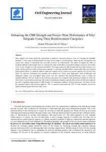
2. Analytical Model Characteristics In this study, three models of 2D steel frames of 8, 10 and 12 stories have been designed with the number of Spans equal with 4, width of 5 m and height of 3.2 m. Mentioned frames are categorized in 4 categories of frames considering the kind of used cross brace in them. These categories include dual system frames having convergent cross and chevron bracing (like upside down V) and having divergent diagonal and Chevron brace. Considering the resistance system duality against lateral loads, designing these frames has been done based on Iran’s 2800 standard. Based on this note, instead of distributing load to ratio of lateral loader elements’' rigidity in buildings with dual systems with braced frames, 100% of lateral power of earthquake can be applied to braces and eliminate comparing the rigidity of lateral loader elements only under the condition that frames be capable of 25% of lateral force. The primary designing of models was done using ETABS software and static analytical method assuming the importance coefficient of building I=1, selected land type II and the location of building in relatively high risk of earthquake area [2, 5, 6]. The weight of whole story in each one of models was determined as 400 kN and the weight of roof as 300 kN. Dual frame system consisting average steel bending frame + steel convergent bracing with behavior coefficient 7 were used for coping lateral loads. In Figure 1. as an example, a view of 10 story frames related to each frame category has been shown. As following in Tables 1 to 4. as samples, obtained sections for each 10 and 12 story model have been proposed.
10s-ed
12s-ed
10s-ev
Figure 2. A view of 10 and 12 story frames with diagonal divergent bracings
12s-ev
Figure 1. A view of 10 and 12 story frames with chevron divergent bracings
527
Civil Engineering Journal
Vol. 3, No. 7, July, 2017
Table 1. Obtained sections for the 10s-ed model Components sections Floor
A Piers
AB frame beam
B Piers
BC frame beam
C Piers
CD frame beam
D Piers
DE frame beam
E Piers
AB Bracing
DE Bracing
10
HE100
IPE240
HE100
IPE240
HE100
IPE240
HE100
IPE240
HE100
2U100
2U100
9
HE120
8
HE140
2U120
2U120
2U140
2U140
2U160
2U160
E Piers
AB Bracing
DE Bracing
HE120
2U100
2U100
HE140
2U100
2U100
HE160
HE160
2U120
2U120
HE120
HE120
HE140 IPE270
HE120
HE140 IPE270
HE120
HE140 IPE270
HE140 IPE270
7 HE180
HE180
HE180
HE180
HE180
5
HE200
HE200
HE200
HE200
HE200
4
HE200
HE220
HE220
HE220
HE200
3
HE240
2
HE260
HE260
HE240
HE260
HE260
1
HE280
HE280
HE280
HE280
HE280
6
IPE300
HE240
IPE300
HE220
IPE300
HE240
IPE300
HE240
`Table 2. Obtained sections for the 12s-ed model Components sections Floor
A Piers
12
HE120
11
HE140
AB frame beam
B Piers
BC frame beam
C Piers
CD frame beam
D Piers
HE100
HE100
HE100
HE120
HE120
HE120
IPE240
DE frame beam
IPE240
10
HE160
HE160
9
HE160
HE180
HE180
HE160
HE160
2U120
2U120
8
HE180
HE180
HE180
HE160
HE180
2U140
2U140
HE200
HE200
HE200
2U140
2U140
2U140
2U140
HE240
2U160
2U160
HE240
HE240
2U160
2U160
7
IPE240
HE160
IPE240
HE200
HE200
6 5
HE240
HE220
HE220
HE220
HE220
HE220
HE220
IPE270
IPE270
4
HE240
HE240
IPE270
HE240
IPE270
3
HE260
HE260
HE260
HE260
HE260
2U160
2U160
2
HE280
HE280
HE260
HE280
HE280
2U160
2U160
1
HE300
HE300
HE300
HE300
HE300
2U160
2U160
E Piers
AB Bracing
DE Bracing
2U80
2U80
2U100
2U100
Table 3. Obtained sections for the 10s-ev model Components sections Floor
A Piers
10 9 8 7 6 5 4 3 2 1
HE100 HE120 HE140
AB frame beam IPE240
HE180 HE200 HE220 HE260 HE280
B Piers HE100 HE120 HE140
BC frame beam
IPE240
HE180 IPE270
HE200 HE220 HE240 HE280
C Piers HE100 HE120 HE140
CD frame beam
IPE240
HE180
IPE270
HE200 HE220 HE240 HE280
D Piers HE100 HE120 HE140
DE frame beam IPE240
HE180
IPE270
528
HE200 HE220 HE240 HE280
HE100 HE120 HE140 HE180
IPE270
HE200 HE220 HE260 HE280
Civil Engineering Journal
Vol. 3, No. 7, July, 2017
Table 4. Obtained sections for the 12s-ev model Components sections AB frame beam
Floor
A Piers
B Piers
12
HE100
11
HE120
10
HE160
HE160
9
HE160
HE180
8
HE180
BC frame beam
CD frame beam
C Piers
HE100
D Piers
HE100
HE120
HE100
HE120
HE120
AB Bracing
DE Bracing
HE100
2U80
2U80
HE120
2U80
2U80
HE160
2U80
2U80
HE180
HE160
HE160
2U100
2U100
HE180
HE180
HE160
HE180
2U100
2U100
HE200
HE200
HE200
2U100
2U100
2U100
2U100
HE240
2U120
2U120
IPE240 IPE240
HE160
IPE240
HE200
HE200
6 5
E Piers
HE160
IPE240
7
DE frame beam
HE240
HE220
HE220
HE220
HE220
HE220
HE220
IPE270
IPE270
4
HE240
HE240
HE240
HE240
2U120
2U120
3
HE260
HE260
IPE270
HE240 HE260
IPE270
HE260
HE260
2U120
2U120
2
HE280
HE260
HE260
HE260
HE280
2U120
2U120
1
HE280
HE280
HE280
HE280
HE380
2U120
2U120
It is noticeable that in order to comparison, designing trend has been assumed equal for all models. In modeling dual frame with divergent bracings, joining beam with length of 0.7 m was used that this value is smaller than 1.6MCE /𝑉𝐶𝐸 , so joining beam is capable of creating shear plastic joint.
3. Story Relative Lateral Displacement According to Iran’s 2800 Standard Regulations As an example for 8 story building with T=0.77: ∆𝑚 ≤ 0.002ℎ
↔
𝑇 = 077𝑠𝑒𝑐 ≥ 0.7
∆𝑚 = 0.7𝑅∆𝑤
→
0.7𝑅∆𝑤 ≤ 0.02ℎ →
∆𝑚 ≤ 0.002ℎ
↔
𝑇 = 077𝑠𝑒𝑐 ≥ 0.7
,𝑅 = 7 ∆𝑤 ℎ
≤
0.02 0.7𝑅
→ 𝐷𝑟𝑖𝑓𝑡 =
∆𝑤 ℎ
≤ 0.00408
,
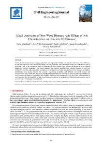
𝑅=7 ∆𝑤 0.02 ∆𝑤 ∆𝑚 = 0.7𝑅∆𝑤 → 0.7𝑅∆𝑤 ≤ 0.02ℎ → ≤ → 𝐷𝑟𝑖𝑓𝑡 = ≤ 0.00408 ℎ 0.7𝑅 ℎ In a same way for frames of 10 and 12 story also, the rate of permitted relative movement is obtained as 0.00408. It is noticeable that these values in non-linear analysis will increase 0.7 R and is respectively for frames of 8, 10 and 12 story equal to 0.02. In below picture frame lateral displacement with dual system has been shown.
Figure 3. Structure’s lateral displacement in structural systems
4. Non-Linear Behavior Modeling of Frame Members in PERFORM 3D Software Since the values of deformations and forces of parts are calculated with controlled behavior by deformation and force from non-linear analysis, so in parts with controlled behavior by force, the obtained forces from analysis using permitted deformation in Figure 4. and Table 3. are proposed for the level of selected performance. According to Figure 4. and Table 3, exploitation coefficients of IO, LS and CP for longitudinal elements that should be entered into software in this research were respectively equal to 2, 7 and 9 [7]. The behavior of steel material, bilinear plastic-elastic with yield stress 𝐹𝑦 = 240 MPa and elasticity module 𝐸𝑠 = 240 MPa and strain hardening effect were considered equal to 3 percent of rebound part.
529
Civil Engineering Journal
Vol. 3, No. 7, July, 2017
Figure 4. The criteria of accepting members [11] Table 5. Modelling parameters and admission criteria in nonlinear methods-steel structural components in seismic rehabilitation guidelines Admission criteria
Modelling parameters
pasty rotation angle, radians Unoriginal
members
Original
members
All members
CP
LS
CP
LS
IO
Ratio of residual to stress c
pasty rotation angle, radians b
Component / effort
a
Beams - Piers 11𝜃𝑦
9𝜃𝑦
8𝜃𝑦
6𝜃𝑦
𝜃𝑦
0.6
11𝜃𝑦
9𝜃𝑦
A:
ℎ tw
≤
3185 √Fye
,
br 2tr
≤
420 √Fye
5. Viscous Damper Liquid viscous dampers are used in this study as inactive control system. All buildings can waste energy during quivers. This energy waste or natural attenuation is created through various resources such as inside created stress and members’ corrosion and fraction. Natural attenuation values are different for various buildings. In seismic designing of structures natural attenuation is equal to approximate 5 percent of critical attenuation. For buildings with low natural attenuation using energy waste systems is very appropriate. An image of general form of an attenuation has been shown in Figure 5.
Figure 5a. General structure of viscous damper [11]
Figure 5b. Maxwell model [11]
In this study, using PERFORM 3D analytical software, attenuations are modeled analytically in steel dual frames. There are some studies by Macris and Constantine (1992) and Constantine and Semites (1993) for achieving an accurate mathematical model for viscous dampers [8, 9]. The best prediction for behavior of viscous dampers is done using Maxwell model that is shown in Figure 4. this model can be stated using below equation. du α
du
P(t) = C0 | dt | sgn [ dt ]
(1)
In this equation α is positive real power that varies from 0.1 to 2 that this value limits to structural function to 0.3 to 1. The symbol of 𝑠𝑔𝑛 is also the function of sign. When α is equal to 1, Equation 1 is used for linear dampers and for other values α introduces non-linear dampers. In this study considering strike pulses, 𝛼 = 0.5 is considered in most of records. Other values of α can be obtained from changing the form of apertures that will change the characteristics of liquid flow as well. Computer program of Perform 3D asks us the graph of power-speed for a non-linear viscous damper element in to Figure 6 piece straight line that after entering information this equation will be same as the form which is shown in Figure 6 [10]. It is noticeable that power-speed graph for linear viscous damper element only has one piece. Available bar viscous element in Perform software only tolerate core forces and consist of one viscous damper part and
530
Civil Engineering Journal
Vol. 3, No. 7, July, 2017
one elastic bar part that are located as series. A view of viscous bar element is shown in Figure 7.
Figure 7. Viscous bar elements [11]
Figure 6. Power-speed relationship [11]
It is noticeable that shown power-speed equation for damper in Figure 6. is similar for modes that damper is in pressure or tensile. It is also noticeable that damper power is unloaded along that very curve which is loaded there. After modelling damper element, they have to be added to structures. Study model in this article is dual steel frame and dampers are installed using diagonal bracing in mentioned frames. First it was assumed that used bracings don’t yield. In this article, Tailor viscous dampers with shown characteristics in Table 5. have been used, these dampers have practical function and are available in market as well. Table 6. The characteristics of used viscous dampers in models Story
FD(kN)
Dmax(mm)
Vmax(mm/s)
C(kN.s/mm)
10
330
100
507
0.65
12
680
50
254
2.68
6. Near and Far Fault Field Earthquake Accelerograms Used records in this research have been extracted from Earthquake Engineering Research Center at UC Berkeley. Selected records include 6 earthquake records that three of them are related to near fault fields and the other three are related to far fault fields. These records are also recorded on soil equivalent for mentioned II soil in Iran’s 2800 standard. II soil in Iran’s 2800 standard is equivalent for soil type B from category USGS. All these accelerograms are coordinated based on maximum effective acceleration to plan basis acceleration to provide the possibility of comparing the results of analyzing frames under the effect of these recorders and the combination of these results is possible. The characteristics of select d records related to near and far fault fields are respectively shown in Table 7. Table 7. Earthquake mapping of near field and far-fault Row
Location
Year
Station
Distance
Magnitude
PGA (g)
1
Kocaeli
1999
Sakarya (90)
3.1
7.4
0.37
2
Chi-Chi,Taiwan
1999
TCu052 W
0.24
7.6
0.34
3
Chi-Chi,Taiwan
1999
TCU072 (W)
1.79
7.6
0.3
4
Imperial valley
1979
Calexico
90.6
6.5
0.27
5
Tabas
1978
Dayhook
107
7.4
0.4
6
Manjil
1990
Abbar
74
7.3
0.51
7. Non-Linear Time History Dynamic Analysis Method In this method, dynamic analysis of structure will be done by giving effect of the acceleration of the earth as a function of time in the base level of the structure and using structures’ dynamic common calculations. Non-linear time history dynamic analysis (moment to moment calculation of building’s reflections under the effect of earthquake real accelerograms) can be used for most of structures. Structure is analyzed in this method under the effect of several recorder accelerograms. Accelerograms should be in accordance with tectonic and geologic characteristics and their compatibility should be provided based on case, with maximum plan spectrum or earthquake spectrum. By non-linear phrases, we mean structure analysis considering its members’ non-linear behavior because of material non-linear behavior, fraction and etc. Analysis is done by summing up or gradual integration during the time using stable average 1 accelerates method. This case is also known as the trapezoid or Newmark method 𝛽 = . In this analytical method, time 4 step of integration should be identified. The number of steps is equal to whole time divided by the time of each step unless analysis finishes before earthquake ending. In non-linear time history dynamic analysis for modeling non-linear
531
Civil Engineering Journal
Vol. 3, No. 7, July, 2017
behavior of structures, three linear non-linear joints have been used. The characteristics of these joints are based on “seismic rehabilitation of existing buildings instructions”. As following, the obtained results from non-linear time history dynamic analysis will be proposed.
8. Stories Relative Displacement Graphs In this section, the results of stories relative displacement graphs of study models are proposed in three modes of without damper, with linear viscous damper and with non-linear viscous damper. In these graphs light curves are related to models with chevron divergent bracings and other curves are related to diagonal divergent bracings. Because of high number of these graphs only the results related to two records of each near and far category. Related results to other records are proposed in column graphs.
Figure 8. Relative lateral displacement of 10 and 12 story frames with diagonal and chevron divergent bracing under the records of near field earthquake
Figure 9. Relative lateral displacement of 10 and 12 story frames with diagonal and chevron divergent bracing under the records of far field earthquake
Figure 10. General relative lateral displacement of 12 story models under the effect of far and near field earthquake
Figure 11. General relative lateral displacement of 10 story models under the effect of far and near field earthquake
532
Civil Engineering Journal
Vol. 3, No. 7, July, 2017
As it can be seen in figures, in most of modes, frames that are designed according to Iran’s 2800 standard affected by applied records show acceptable relative lateral displacement. With installing viscous dampers in models, it was seen that in model of using linear and non-linear viscous dampers, responses reduced significantly that this reduction in more in using non-linear viscous dampers. Affected by near field records, models with chevron divergent bracings showed less relative lateral displacement while affected by far fields records, models having diagonal bracings show less relative lateral displacement. Affected by both applied records of far and near fields, after installing damper, higher modes’ critics have been prevented in structures with more heights. First mode is dominant on models other models. In Figures 10 and 11. it is seen that the most percent of reducing response after installing viscous dampers is in diagonal divergent bracing models and affected by near field records.
9. Stories Lateral Displacement Graphs As following the graphs of study models lateral displacement are shown in three modes of without damper, with linear viscous damper and with non-linear viscous damper. First, in Figures 12 to 15. the graphs are proposed related to displacement response under the effect near field records and after that in Figures 15 to 19. related graphs to far field records from fault. By paying attention to these graphs it can be seen that affected by a stable process for designing, models with diagonal divergent bracing under the effect of both two categories of far and near field records, showed more lateral displacement that these displacements reaches to its most rate under the effect of ChiChi052 records (near field) and Imperial Valley (far field). In all these shapes the effect of linear and non-linear viscous dampers in reducing structure responses can be seen. As it is seen non-linear viscous damper reduces the displacement response of models more.
Figure 12. Lateral displacement of 10 and 12 story model, Chevron brace
Figure 13. Lateral displacement of 10 and 12 story model, Diagonal brace
Figure 14. Lateral displacement of 10 and 12 story model, Chevron brace
Figure 15. Lateral displacement of 10 and 12 story model, Diagonal brace
Figure 16. Lateral displacement of 10 and 12 story model, Chevron brace
Figure 17. Lateral displacement of 10 and 12 story model, Diagonal brace
533
Civil Engineering Journal
Vol. 3, No. 7, July, 2017
Figure 18. Lateral displacement of 10 and 12 story model, Chevron brace
Figure 19. Lateral displacement of 10 and 12 story model, Diagonal brace
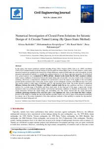
10. Shear Graphs As following, the values of obtained base shear for models in Table 8. and Figures 20 and 21. are shown. Noticing these values, it is observed that the values of base shear affected both two records of far and near fields are more in models with diagonal bracings than models with chevron bracings. These values also in most of the times will reduce with installing dampers in models. The most percent of reduction happens because of using non-linear dampers, although these dampers produce more shear values that linear viscous dampers under the effect of ChiChi052 and Imperial Valley. These results can be seen in column graphs of Figures 20 and 21. as well. Table 10. Amount of basic shear in 10 and 12 story model (ton)
far field
near field 10 story far field
18.3
Imperial Valley
27.27
nonlinear damper
30.29
ChiChi072
Linear damper
ChiChi052
Without damper
23.8
nonlinear damper
12 story
Kocaeli
19.9
19.3
14.22
11.3
12
26.04
30.9
17.78
16.37
19.6
13.26
11.98
11.6
7.96
7.09
24.11
26.02
14.78
15.43
15.98
Tabas
9.16
7.8
8.73
5.96
4.8
5.45
Manjil
15.5
11.21
9.8
10.18
7
6.4
Kocaeli
24.48
17.8
16.32
21.06
20.9
13.67
ChiChi052
37.16
24.98
22.68
25
24.01
19.75
ChiChi072
18.58
12.87
11
13.75
13.5
8.81
Imperial Valley
33.94
22.79
12.66
22.34
21.33
17.8
Tabas
10.5
7.56
7.89
7.84
7.6
5.58
Manjil
20
11.17
8.11
16.4
16.1
7.48
Base Shear 12 Story
40
0 1
3
Kocaeli Chi chi 052w Chi chi 072w Imperial Valley Tabas Manjil Kocaeli Chi chi 052w Chi chi 072w Imperial Valley Tabas Manjil
Figure 20. Amount of basic shear in 10 story model
Base Shear (Ton)
Base Shear (Ton)
Base Shear 10 Story
20
With Chevron brace
Linear damper
near field
Without damper
Record
With diagonal eccentrically brace
40 20 0 1
3
Kocaeli Chi chi 052w Chi chi 072w Imperial Valley Tabas Manjil Kocaeli Chi chi 052w Chi chi 072w Imperial Valley Tabas Manjil
Figure 21. Amount of basic shear in 12 story model
534
Civil Engineering Journal
Vol. 3, No. 7, July, 2017
11. Displacement Time History Graph In this section, roof displacement time history graphs related to 12 story models are shown in Figures 22 to 25. In each one of these figures, there are three responses related to modes without damper, with linear viscous damper and with non-linear viscous damper. First in Figures 22 and 23. graphs related to near field records and after that in Figures 24 and 25. related graphs to far field records to fault have been shown. In these graphs, the effect of various linear and non-linear dampers in reducing responses can be observed.
Figure 23. Time history of a model with divergent diagonal braces
Figure 22. Time history graph of a model with divergent Chevron braces
Figure 25. Time history of a model with divergent diagonal braces
Figure 24. Time history graph of a model with divergent Chevron braces
12. Conclusion
In dual steel frames, structures under the effect of near earthquake records to fault compared to structures under the effect of other records show different behaviour. Although numerical results which have been obtained in this research depend completely on the characteristics of designed frames and records and other factors such as construction conditions but this result that structures have different behaviour under the effect of these records can be generally accepted.
In most of modes, non-linear viscous dampers with 𝛼 = 0.5 have better performance than linear viscous dampers in reducing models’ responses (stories relative lateral displacement and lateral displacement and base shear).
In most of modes, under the effect of near field earthquake, created movement in structural models is more than mode that far filed records has been applied.
After installing viscous dampers in models, all models are damped in first mode and viscous damper don’t let higher modes to be critical.
Under a stable designing process, in models with diagonal divergent bracing, the values of relative lateral displacement and lateral displacement were recorded with higher values. The percent of stated responses values reduction after installing damper also was more in these frames. In another word viscous dampers have better efficiency in improving the performance of constructional systems with less lateral hardening.
Viscous damper prevents the entry of structure to non-linear area and have appropriate performance in wasting
535
Civil Engineering Journal
Vol. 3, No. 7, July, 2017
entered energy because of pulse kind strikes (especially under the effect of near field records).
Non-linear dampers with 𝛼 = 0.5 are more capable of attracting energy of pulse kind strikes related to near field earthquakes and reduce structural responses in greater extent.
Compared to linear viscous dampers, in some cases, using non-linear viscous dampers increases base shear.
During a stable designing process, the values of relative displacement in models with chevron divergent bracings are less than similar values in models with diagonal divergent bracings.
13. References [1] Ali, Mir M., and Kyoung Sun Moon. "Structural developments in tall buildings: current trends and future prospects." Architectural science review 50, no. 3 (2007): 205-223. [2] Buildings plan against earthquake regulations (2800 standard Iran), Third edition, Institute of standards and industrial research of Iran, 2005. [3] UBC, Uniform Building Code, Volume 2 , Structure Engineering Design Provision, 1997. [4] Whittaker, A. S., I. D. Aiken, D. Bergman, P. W. Clark, J. Cohen, J. M. Kelly, and R. E. Scholl. "Code requirements for the design and implementation of passive energy dissipation systems." In Proc., of ATC 17-l Seminar on Seismic Isolation, Passive Energy Dissipation, and Active Control, vol. 2, pp. 497-508. 1993. [5] The tenth issue of National Building Regulations, (Design and construction of steel buildings), Department of Housing and Urban Development, 2008. [6] Computer and Structure Inc., ETABS. "Linear and nonlinear static and dynamic analysis and design of building systems", Computer and Structure Inc., Berkeley, Calif, 2004. [7] FEMA, Prestandard. "Commentary for the seismic rehabilitation of buildings." FEMA-356, Federal Emergency Management Agency, Washington, DC (2000). [8] M.C. Constantinou and M.D. Symans, “'Experimental and Analytical Investigation of Seismic Response of Structures with Supplemental Fluid Viscous Dampers”, Report No.NCEER-92-0032, National Center for Earthquake Engineering Research, Buffalo, New York, 1992. [9] N. Makris and M.C. Constantinou, “Spring-viscous Damper Systems for Combined Seismic and Vibration Isolation”, Earthquake Engrg. Struct. Dyn.,21 (8), 649-664 (1992). [10] Graham, P. “PERFORM-3D ver 5”. Computer and Structure Inc, (2010). [11] Hamid Reza Ashrafi, Amir Mohammad Amiri, Soroush Dadgar, Peyman Beiranvand,” Studying the effects of earthquakes near and far fault region on seismic behavior of dual frame equipped with viscous damper”, JVE INTERNATIONAL LTD. VIBROENGINEERING PROCEDIA, OCT 2016, VOL. 9.pp,23-28.
536