Available online at www.CivileJournal.org
Civil Engineering Journal Vol. 4, No. 5, May, 2018
A Numerical Analysis of T-Shaped Reinforced Concrete Beams Strengthened with Polymeric Strap of CFRP and GFRP by Finite Element Method Mehrdad Marefat Naeini a*, Sayed Mahdi Moghadasi b, Mostafa Omidi Bidgoli c a
Master student of Civil Engineering, Islamic Azad University Golpayegan, Esfahan, Iran. b
PhD. Student of Civil Engineering, Amirkabir Industrial University, Tehran, Iran. c
Member of Academy, Mechanical Engineering Faculty Badroud, Esfahan, Iran. Received 19 March 2018; Accepted 21 May 2018
Abstract In recent decades, researchers and structural engineers have shown great interest in the use of Fiber Reinforced Polymer (FRP) plates/sheets for maintaining strength and durability in the utilization of concrete structures. In this study, reinforcedconcrete beam with T-shaped cross-section is reinforced with Carbon Fiber Reinforced Plastic (CFRP) plates and Glass Fiber Reinforced Plastic (GFRP) plates under 4-points inflections by finite element method. In order to analyze the performance of the polymer plates used in the reinforcement of the considered concrete beams, some sheets with 5cm and 10 cm width having different formation patterns are joined to the concrete area. For this purpose, the angle between the lines of the plates and the longitudinal axis of the beam is varied based on four different degrees of gradations, from 30 to 90°. In addition, the role of these sheets in limiting the deformation of the beam in its U-shaped and full-wrapping conditions is studied. The transversal distance between the plates is also considered as equal to the width of plates. Seventytwo samples of concrete beams with C30 and C50 grades which were strengthened with polymer plates are compared with non-polymeric concrete beams. The numerical analysis results illustrate that the use of the different formation patterns and deflection angle of plates cause differences in the process of beam settlement. Further, the results show that C50 grade concrete samples are most effective in the reduction of concrete deformation when carbon fibers of 5cm width are used at an angle of 30 degrees with beam linear axis and traversal formation pattern. On the other hand, among the C30 grade samples, the best performance is related to the use of 5 cm carbon fibers which were utilized as full-wrapping. Under both aforementioned circumstances, the possible amount of the polymeric beam settlement over non-polymeric beam will decrease by about 50%. Keywords: CFRP; GFRP; T-shaped Concrete Beam; Polymer Plates; Reinforced Concrete (RC).
1. Introduction In recent years, the reinforcement of existing concrete buildings is regarded as the most important issue in civil engineering. An overview of the damages caused by loading shows that until now, a high percentage of reinforced concrete (RC) buildings do not have enough or acceptable strength to confront static or dynamic loads, because these constructions are designed on the basis of old rules and regulations, and most of them do not comply with the new bylaw. Moreover, operational insufficiencies and weaknesses have also increased the vulnerability of these concrete structures to the applied loads. Accordingly, the importance of strengthening these buildings with authentic, plain and economical reinforcement methods is now widely recognized. In other words, each concrete structure needs a considerable * Corresponding author:
[email protected] http://dx.doi.org/10.28991/cej-0309152 This is an open access article under the CC-BY license (https://creativecommons.org/licenses/by/4.0/). © Authors retain all copyrights.
1006
Civil Engineering Journal
Vol. 4, No. 5, May, 2018
performance, such that its strength and productivity are maintained throughout its service life. Regarding the increasing necessity of constructing and repairing concrete structures, the developed countries as well as Iran, which is also undergoing massive developments in concrete buildings, can be categorized as the countries taking the issue of repair and reinforcement of structures seriously. One of the common methods used for strengthening reinforced concrete in the past is the joining of steel sheets to the construction. Extensive studies have been done on the use of polymer sheets (FRP) in recent years, which has led to the replacement of steel sheets with FRP sheets. One of the significant advantages of FRP sheets is their high ratio of strength to weight. Typically, FRP sheets are about 2-10 times more resistant than steel sheets if at most they weigh up to 20% of the steel sheets’ weight [1, 2].
2. Technology of Carbon Fiber Reinforced Polymer (CFRP) and Glass Fiber Reinforced Polymer (GFRP) Strips 2.1. Glass Fibers (GFRP) 2.1.1. Glass Fiber Production Procedure
A combination of silicate melts, potassium hydroxide and various metal oxides are used to manufacture glass fibers. After passing through a fine membrane, the melts are super cooled, leading to the production of glass fibers with diameters of 5-24 𝜇𝑚 are produced. Ultimately, the produced fibers are woven compactly; during the process, the fibers are alternatively coated with resin to minimize their abrasion. 2.1.2. Various Types of Glass Fibers
1. Electrical glass fibers (E-Glass). 2. Structural glass fibers (S-Glass). 3. Chemical glass fibers (C-Glass). 4. Alkali Resistant-Glass (AR-Glass). Table 1. Mechanical characteristics of various glass fibers Type
Tensile strength (MPa)
Young’s modulus (GPa)
Elongability (%)
E-Glass
3445
72.4
4.8
S-Glass
4585
86.9
5.4
C-Glass
3310
68.9
4.8
AR-Glass
3241
73.1
4.4
2.2. Carbon Fibers (CFRP) 2.2.1 Carbon Fiber Production Procedure
Artificial silk, polyacrylonitrile, and tar derived from oil refinery are used as raw materials for the production of carbon fibers. Among all FRP fibers, carbon fibers have the highest Young’s modulus, which is why they are recommended for structural improvement purposes. 2.2.2. Various Types of Carbon Fibers
1. Carbon fibers of PAN type. 2. Pitch-based carbon fibers, which are essentially derived from the distillation of coal. Table 2. Mechanical characteristics of various types of carbon fibers Fiber characteristic
Young’s modulus (GPa)
Ultimate strength (MPa)
Yield strain (%)
General application
220 – 240
2050 – 3790
1.2
High strength
220 – 240
3790 – 4820
1.4
Very high strength
220 – 240
4820 – 6200
1.5
High modulus
340 - 520
1720 - 3100
0.5
3. A Quick Review of Past Studies The utilized technology in FRP sheets was comprehensively studied by some researchers in the early 90s, for the sake of achieving some improvements in concrete construction. The technology was developed by Meier et al. in Switzerland, as a result of their work on a series of studies based on previous experiments on reinforced-concrete beams
1007
Civil Engineering Journal
Vol. 4, No. 5, May, 2018
strengthened with CFRP sheets, which had been initiated since 1984 [3]. Saadatmanesh and Ehsani conducted an experimental study with the aim of evaluating the static strength of reinforced-concrete beams strengthened with GFRP plates. Their experimental results showed that the joining of polymer plates to the tensile mode of the concrete beams caused considerable enhancement in flexural strength. Further, this strengthening caused an increase in flexural hardness, plasticity and a decrease in beam deflection in time of fracture [4]. Mosallam and Ayman focused on the role of CFRP and GFRP plates in increasing the shear strength and repairing pre-loaded reinforced-concrete beam in an experimental study. The results of the study showed that the span-to-depth ratio of the beam is the most significant factor in controlling the beam’s shear mode-failure and subsequently the effect of polymer plates on the amount of shear strength [5]. Lee et al. scrutinized the shear-behavior of 14 deep T-shaped reinforced-concrete beams strengthened with CFRP sheets in such a way that the utilized fibers had different angles in relation to each other. The considered variables in Lee’s study included the arrangement of the fibers in different directions and reinforced-length of beams. According to the results of the study, there are possibilities of partial lamination involving common failures in CFRP sheets [6]. Also, another research done by Moghadasi et al. in 2012 showed that the condition of embedment and details of yokes and their distances in a bending frame has an important effect on loading capacity of structures. Thus, the article suggested the adoption of FRP for beams with technical deficiency that need strengthening [7]. Ferreira et al. put some samples under inflection and shear for the sake of checking the mechanism of shear-strength of concrete beams reinforced with FRP plates. Additionally, to compare the experimental results, some numerical analyses of the studied beam’s shear-strength were performed. The study’s results show that the use of FRP sheets causes pattern modification, cracks-growth limitation and stress reduction in concrete section and steel bars [8]. Tetta et al. put their efforts on an experimental study that paid attention to strengthening rectangular reinforcedconcrete beams with composite materials. The parameters of this study include types of textiles, their positional forms, arrangement of polymeric jacketing and number of polymer layers. Fourteen concrete beams were constructed and tested under bending load. The results illustrate that FRP sheets are more effective in increasing the shear capacity of concrete beams than Textile Reinforced Mortar (TRM) jackets. Nevertheless, increasing the number of TRM jacketing layers causes a considerable enhancement in the effectiveness of the jackets for augmenting the bending-shear capacity of concrete beams [9]. The small deflection analysis of equal two-span continuous simply supported GFRP beams with CFRP flange stiffening is presented for the case of equal mid-span point loads. The analysis is based on a combination of the methods of Influence Coefficients and Transformed Sections and leads to closed-form equations for tractions and deformations. Symmetric mid-span load tests on five beams-one all-GFRP and four CFRP stiffened GFRP beams-are described and mid-span deflections, support rotations are used to establish the accuracy of the analysis for predicting their deflection serviceability limits and, hence, their possible utility for the preliminary design of such beams [10]. Carbon fibre reinforced polymer (CFRP) externally bonding is an efficient and effective method to strengthen damaged steel beams, and thereby prolong their service life. However, debonding failure, which requires accurate predictions to ensure safety, can occur before the full usage of CFRP. In this study, the notched steel beams strengthened with CFRP plate were simulated by finite element method where the mixed-mode cohesive law was employed to determine the interfacial stress. The load-deflection curves and strain development at different load levels from experimental study were used to verify the validity of the numerical model. The interfacial stress distribution with increasing load was analysed, and good correlation with theoretical calculations at elastic stage was observed. In contrast to the previous elastic analytical study, the plastic behaviour of the CFRP strengthened notched steel beams was revealed. More importantly, interfacial crack initiation, propagation and debonding were accurately simulated. This simulation method can be used to predict debonding process in actual engineering applications. In addition, parametric analysis was conducted to assess the effects of notch depth, CFRP elastic modulus and CFRP thickness. The ultimate load and ductility decreased substantially with increasing notch depth. Furthermore, although increased bearing capacity was achieved by increasing the CFRP elastic modulus and thickness, ductility decreased and premature debonding failure occurred more easily [11]. This study investigated the punching behavior of reinforced concrete slabs strength with carbon-fiber-reinforced polymer (CFRP). We tested a total of thirteen RC slabs, each having 965 mm length, 680 mm width, and 60 mm thickness, each slab was reinforced with two layers of CFRP of area (40 × 40 cm 2). The variables in the experimental program were: pre loading (60% and 80%) of ultimate load (load of control slab) and orientation of the fiber of CFRP (0°, 45°, (0°/90°) and (45°/135°)). Test results showed that the capacity of ultimate load of strength of the slabs is increase (23%–65%) compared with slab unreinforced. The results illustrate that carbon-fiber-reinforced polymer (CFRP) reinforcement is perfect in reducing the deflection (3%–48%). The CFRP strengthening is perfect in reducing
1008
Civil Engineering Journal
Vol. 4, No. 5, May, 2018
the strain [12]. The present study develops a theory for the elastic analysis of a preloaded wide flange steel beam, strengthened with two glass fiber-reinforced polymer (GFRP) plates bonded to both flanges, then subjected to additional loads. Starting with the principle of stationary potential energy, the governing equilibrium equations and corresponding boundary conditions are formulated prior to and after GFRP strengthening. The resulting theory involves four coupled equilibrium equations and 10 boundary conditions. A general closed form solution is then provided for general loading and boundary conditions. Detailed comparisons with three-dimensional finite-element solutions show that the theory provides reliable predictions for the displacements and stresses. A parametric study is then developed to quantify the effects of strengthening, GFRP plate thicknesses, and preexisting loads on the capacity of the strengthened beam [13].
4. Numerical Analysis of T Shaped Concrete Beam Strengthened with CFRP and GFRP The continuous growth and universality of numerical analysis methods alongside the high accuracy of their procedures has made it possible to scrutinize the behavior of RC without the need for experimental studies. Further, the results of numerical studies show that the behavior of the parts of RC strengthened with FRP plates can be estimated by numerical methods rather than expensive examinations. Hence, this study attempts to perform a numerical simulation that lays the groundwork for a better comprehension of the behavior of the bending parts of RC T-section strengthened with FRP sheets and compensates for the absence of experimental results.
5. Mechanical and Geometric Specifications of the Analyzed Concrete Beam In the present study, in order to study the effect of polymer plates on the behavior of T-shaped RC, a beam with the dimensions shown in Figure 1 is introduced to the software. The value of Poisson’s coefficient is 0.2 and its elasticity modulus(𝐸𝑐 ) is determined by means of the following formula, in which (𝑓𝒄′ ) is considered as concrete’s compressivestrength characteristic. 𝐸𝐶 = 4700√𝑓𝐶′
(1)
In the analysis of FE method, there are some presented stress-strain relations of unconfined concrete under stress and tension which are considered as significant parameters in the introduction of concrete plasticity modulus if experimental results are not available to enable the use of authentic proposals of former studies. As an example, Hognestad proposed model is regarded as one of the high usage ones among others (Figure 2). The rising tributary model by means Figure 2 can be taken out. In this relation (𝑓𝑐" ) is the maximum tension in the concrete part that can be obtained by the 3 rd relation. In such relation, the (𝐾𝑠 ) modulus of concrete with 15, 20, 25, 30 cylindrical stress-strength can be figured out as greater than or equal to 35 mega Pascal, which are equal to 0.92, 0.93, 0.95, 0.97 respectively. The descending tributary of the curve prolongs linearly from (ℇ0 , 𝑓𝑐" ) to (ℇ𝑢 , 0.85𝑓𝑐" ). In this study, the amount of concrete tensile-strength is equal to 0.0038 according to the proposed ACI-318 regulation on the basis of relation number 4 and the amount of (ℰ𝑢 ) (ultimate strain like concrete compressive-fracture). Consequently, two types of concrete, C30 and C50 grades, used in the study of T-shaped concrete beams’ behavior are analyzed. 2ℇ𝐶 ℇ𝐶 2 𝑓𝐶 = 𝑓𝐶" [ −( ) ] ℇ0 ℇ0
(2)
𝑓𝐶" = 𝑘𝑆 . 𝑓𝐶′
(3)
𝑓𝑡′ = 0.7√𝑓𝐶′
(4)
Figure 1. General Schematic of Loading and Dimensions of the Analyzed Beam (in mm)
1009
Civil Engineering Journal
Vol. 4, No. 5, May, 2018
Figure 2. Stress-Strain Hognestad Curve and Adapted Hognestad for under Pressure Concrete
6. Mechanical and Geometric Specifications of Reinforced Steel Rods For the purpose of reinforcement, two types of bars are used (as shown in Table 1). The arrangement of the reinforcement is portrayed in Figure 3. In order to define the interaction between concrete and bars to the software, bars are hidden inside of the concrete by use of the embedded program. As a result, the effects of sliding between concrete and reinforcement are ignored. Table 3. Specifications of Longitudinal and Latitudinal Rods Type
Rupture Strength (Mpa)
Tension Strength (Mpa)
Modulus of Elasticity (Mpa)
Yoks (D6)
447
743
2.1×10⁵
Longitudinal rod (HD22)
436
642
2.4×10⁵
Figure 3. Setting of Steel Rods in Concrete Beam
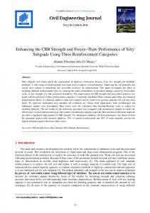
7. Mechanical and Geometric Specifications of FRP and Reinforcing Steel Rods In order to analyze the reinforced samples, different formation patterns are considered for each CFRP and GFRP sheets, which are 5 and 10 cm wide. Accordingly, the angle between the lines of the plates and the linear axis of the beam (α) is varied based on four different degrees of gradations, including 30, 45, 60 and 90 (Figure 4). If α equals to 30, 45 and 60 degrees, the parallel reinforced samples (Figure 5) and those with polymer plates that have a traversal ratio (X patterns) toward each other will be analyzable (Figure 5b). Also, in this analysis, when α equals to 90 degrees, the performance of the sheets may be similar to U-shaped or full-wrapping (T-shaped patterns) that is clung on the concrete area (Figure 4). Other mechanical characteristics of CFRP and GFRP sheets are shown in Table 2.
1010
Civil Engineering Journal
Vol. 4, No. 5, May, 2018
Figure 4. Variables Concerned with each of the Decorative Patterns by Polymeric Stapes
a
b Figure 5. Practiced Patterns for Polymeric Straps (a) Parallel and (b) Crucial Table 4. Specifications of Polymeric Straps of CFRP and GFRP Type of Fibre
Modulus of Elasticity (MPa)
Rupture Strength (MPa)
Thickness (mm)
CFRP
165
2800
1.2
GFRP
19
279
0.864
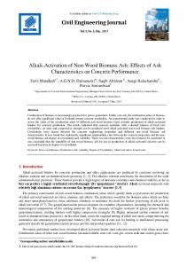
8. An Analysis of the Results of Numerical Analysis In order to analyze the behavior of T-shaped concrete beam strengthened with CFRP and GFRP sheets, the beam’s deformation (settlement) at the central points of the controlling points’ bottom line (beam’s misspent) is investigated. In the first step of parametric analysis, the behavior of the non-polymeric concrete beam with T-shaped cross-section under 4-points inflection is analyzed. Based on Figure 6, the graph illustrates the ratio between the reactional leaning point and the controlling points. According to the results of the numerical analysis of loading, the reactional power for C50 and C30 grades concrete increases to about 570 and 515 kn respectively. After this phase, by continuing the loading process, when the measures of C50 and C30 grades concrete beam settlement with T-shaped cross-section reaches 44/15 and 31/51 mm respectively, the failure of the concrete beam occurs. 600
537.518
557.077
523.361
570.655
500 526.291
515.118 502.899 501.351
Force (kn)
400
463.809
300
200
100
Concrete Grade (C30) Concrete Grade (C50)
0 0
5
10
15
20
25
30
35
40
Deflection (mm) Figure 6. Graph of Force – Deflection for T Shaped Concrete Beam without Polymeric Strap
1011
45
Civil Engineering Journal
Vol. 4, No. 5, May, 2018
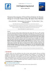
9. An Analysis of the Results of Concrete Beam Grade C50 Retrofitted with CFRP and FRP According to Figure 7, FRP strap in parallel form causes decrease in deflection, and in this regard, CFRP has a better performance than GFRP. Generally, for every type of FRP, the best function occurs when FRP straps are at 30° compato the longitudinal axis of the lateral surface of the beam. Therefore, based on numerical analyses, the effect of CFRP in the limitation of the deflection of the beam decreases with an increase in 𝛼). This trend is also true for GFRP straps, except when 𝛼 changes from 45° to 60° . According to this figure, the amount of sensitivity in samples retrofitted with CFRP straps of various 𝛼 is much more than that of the samples strengthened with GFRP. Numerical analysis indicate that with respect to samples retrofitted with FRP straps of 10 cm wide, for every samples reinforced with CFRP and GFRP, the maximum effect of polymers in decreasing beam deflection occurs when straps are at 45° with respect to the longitudinal axis of the peripheral surfaces. Changes for bending member due to deflection are not considerable. This position is also for equals and. The minimum effect of straps in the limitation of beam deflection occurs when straps are bound parallel to latitudinal rods (𝛼 = 90°) of the peripheral surface of concrete beams.
38.09
38.80
36.30
37.96 41.27
33.27
30.27
30 23.25
Deflection (mm)
35
37.60
35.63
40
31.44
45
38.47
50
44.15
At this angle, by increasing the number of polymeric straps and using patterns with U shape curled around, the amount of deflection reduces. In addition, these reductions in deflection, specifically in samples with GFRP straps, are not so considerable.
25 20
15 10 5 0 Sample Missing Reinforcement
30
45
60
90
FRP straps type of array for - (a) 5 cm
1012
U
T CFRP
GFRP
30 25
40.32
24.57
26.22
35
Deflection (mm)
35.12
37.20 31.20
40
36.63
37.38
45
39.61 41.88
44.15
50
Vol. 4, No. 5, May, 2018
37.98 40.88
Civil Engineering Journal
20 15 10 5 0 Sample Missing Reinforcement
30
45
60
90
FRP straps type of array for - (b) 10 cm
U
T CFRP
GFRP
Figure 7. Deflection of Concrete Beam Grade C50 Retrofitted with Polymeric Straps in Longitudinal and Parallel forms with Widths of (a) 5 and (b)10 cm
10. A Comparison between the Effects of Different Arrays of Parallel and Crucial Straps on Deflection Reduction in Concrete Beams of C50 The results of numerical analysis show that by using CFRP straps with 5cm of crucial array (Figure X), when 𝛼 increases, the ascending order of deflection is linear. Thus, by increasing 𝛼 from 45° to 60°, the rate of increase in deflection of the beam in crucial format is more compared with parallel format. Arraying patterns has a more appropriate effect on deflection. On the other hand, in samples retrofitted with GFRP with angles of 30° and 60°, the use of crucial arrays causes increase in straps’ role of decreasing deflection in beams. 44
Use of Straps with Parallel Array of CFRP ( | | )
42
Use of Straps with Parallel Array of GFRP ( | | )
40
Use of Straps with Cracial Array GFRP ( X )
Deflection (mm)
38
Use of Straps with Cracial Array CFRP ( X )
37.20
37.32
37.38
36 34
35.45
30.17
32 30
36.52
36.63
32.59
27.64
31.20
28 26 24
26.22 24.57
22 20 30
45
60
Angle between Polymeric Straps with Longitudinal Axis (Degree) Figure 8. Comparing Deflection of Concrete Beam Grade C50 Retrofitted with FRP Straps in parallel and Crucial Arrays with 10 cm
1013
Civil Engineering Journal
Vol. 4, No. 5, May, 2018
44
42.01
42 38.83
40 38
35.63
Deflection (mm)
36
38.47
37.60 33.09
34 32
30.27
34.96
30
31.44
28 27.73
26 24
23.25
Use of Straps with Parallel Array of CFRP ( | | )
Use of Straps with Cracial Array CFRP ( X )
22
Use of Straps with Parallel Array of GFRP ( | | )
22.07
20
Use of Straps with Cracial Array GFRP ( X )
30
45
60
Angle between Polymeric Straps with longitudinal axis (Degree) Figure 9. Comparing Deflection of Concrete Beam Grade C50 Retrofitted with FRP Straps in parallel and Crucial Arrays with 5 cm
11. An Analysis on the Results of Concrete Beams Grade C30 Retrofitted with CFRP and GFRP Straps According to Figure 10-A, the amount of deflection of concrete beam grade C30 with different array patterns of FRP straps of 5 cm (retrofitted with GFRP and CFRP) shows that when parallel straps are used, changes in 𝛼 from 30° to 60° for GFRP straps do not have a considerable effect on deflection of beams. On the other hand, for concrete beam grade C50 retrofitted with GFRP, increasing the angle of the straps (𝛼)from 30° to 60° causes a decrease in deflection and improvement in straps function. Therefore, when 𝛼 is 60°, the amount of deflection in beams retrofitted with CFRP and GFRP are very close. Thus, an increase in 𝛼 in both straps of GFRP and CFRP from 60° to 90° causes an increase in deflection in the retrofitted beams. Figure 10-B shows that when strengthening C30 beams with CFRP and GFRP straps of 10 cm width, the changes in the amount of deflection based on different measures of 𝛼 and arrays have a different trend. In samples with CFRP straps, the minimum deflection occurs when the angle of the straps equals 30°, while in retrofitted samples with GFRP straps, an angle of 45° causes the minimum deflection. Generally, the trend of deflection change in C30 beam with an increase in the angle of polymeric strap from 30° to 90° is different from that of C50 beam.
1014
18.07 18.70
30
45
60
15.68 18.34
18.28
20
17.92
Deflection (mm)
25
16.93 18.55
24.83
30
21.04 22.56
28.21
35
Vol. 4, No. 5, May, 2018
31.51
Civil Engineering Journal
U
T
15 10 5 0
GFRP
60
23.34
25.26
22.75 25.55
19.55
19.16
45
21.08
18.48
16.85
25
20
23.58
25.20
30
Deflection (mm)
CFRP
FRP straps type of array for - (a) 5 cm
22.93
35
90
31.51
Sample Missing Reinforcement
15
10
5
0 Sample Missing Reinforcement
30
90
FRP straps type of array for - (b) 10 cm
U
T CFRP
GFRP
Figure 10. Deflection of Concrete Beam Grade C30 Retrofitted with Polymeric Straps in Longitudinal and Parallel forms with Widths of (a) 5 and (b)10 cm
12. A Comparison between the Effects of Polymeric Straps in Crucial and Parallel Array Patterns on Decreasing Deflection in Concrete Beams of Grade C30 Based on Figure 11, a comparison between crucial and parallel array with 5cm straps of CFRP at 30° and 45°, shows equal amounts of deflections. But with an increase to 60°, the crucial type has a better performance in limiting deflections. On the other hand, for retrofitted samples with GFRP at 30°, 45°, 60°, the performance of glassed straps in crucial and parallel arrays is different. At 60°, straps with parallel form have a better result in decreasing deflection of T shaped beams.
1015
Civil Engineering Journal
Vol. 4, No. 5, May, 2018
Comparing the parallel and crucial patterns of FRP straps of 10 cm in C30 T shaped beams in Figure 12 shows that under a unified angle, all CFRP and GFRP polymeric straps with crucial form have a better function than the parallel ones with respect to deflection. The only exception is the sample whose straps are fixed at 45° to peripheral sides of the beam. Besides, as shown in Figure 12, crucial pattern of straps with 10 cm of width causes increase in sensitivity of deflection in beam compared with the parameter of angle in the straps.
27
Use of Straps with Parallel Array of CFRP ( | | )
28.46
29
Use of Straps with Cracial Array CFRP ( X ) Use of Straps with Parallel Array of GFRP ( | | )
28.21
Use of Straps with Cracial Array GFRP ( X )
24.83
Deflection (mm)
25 23
22.12
23.58
20.16
21 19 17
18.27
17.86
18.70
18.28
17.92
18.07
15 30
45 Angle between Polymeric Straps with longitudinal axis (Degree)
60
Figure 11. Comparison of Deflection in Concrete Beam Grade C30 Retrofitted with Polymeric Straps in Parallel and Crucial Array with 5 cm of Width Use of Straps with Parallel Array of CFRP ( | | )
31
Use of Straps with Cracial Array CFRP ( X )
29.00
Use of Straps with Parallel Array of GFRP ( | | )
29
Use of Straps with Cracial Array GFRP ( X )
Deflection (mm)
27
25.97
25.20
25 23
22.93
23.58
22.28
22.82
21.47
21 18.48 19
16.85
19.16
17
17.75
15 30
45 Angle between Polymeric Straps with longitudinal axis (Degree)
60
Figure 12. Comparison of Concrete Beam Deflection for Grade C30 Retrofitted with Polymeric Straps in Parallel and Crucial Array with 10 cm of Width
13. Amount of Relative Decrease in Deflection of T Shaped Concrete Beam with the Aid of FRP Straps In Tables 3 and 4, the percentage of decrease in deflection in 72 different retrofitted beams compared with beam not retrofitted with FRP are shown. According to the results, for every sample of concrete grade C50, the maximum decrease in deflection occurs when CFRP straps with 5cm of width at 30° and crucial array are used. This position is able to
1016
Civil Engineering Journal
Vol. 4, No. 5, May, 2018
decrease deflection in the beam up to 50%; in contrast, the minimum effect of polymeric straps happens when GFRP straps with 10cm width in a parallel direction with latitudinal rods (𝛼 = 90°) are used. In this case, deflection of the beam without strap is only limited to 5%. When C30 grade concrete is used, the minimum effect is felt when 5cm straps of GFRP at 30° to the longitudinal axis of concrete surface are fixed. In this grade, the best performance is achieved by straps of 5cm CFRP that are curled completely around, and in this case deflection decreases by up to half the position without strap. Table 5. Proportion of Decrease in Deflection of Concrete Beam Grade C50 Retrofitted by Polymeric Straps to a Beam without Strap (%) Type of Array Polymeric Strap
Width (cm)
CFRP
GFRP
𝟒𝟓°
𝟑𝟎° II
X
II
𝟔𝟎° X
II
X
𝟗𝟎°
U shape
T shape
5
47.33
50.01
31.44
37.2
28.79
25.04
14.01
17.77
24.65
01
40.61
37.39
44.35
31.66
29.32
19.71
10.28
13.97
20.46
5
19.29
20.82
12.86
4.86
14.83
12.06
6.52
12.13
13.73
01
15.33
26.19
17.03
15.47
14.75
17.28
5.15
7.41
8.67
Table 6. Proportion of Decrease in Deflection of Concrete Beam Grade C30 Retrofitted by Polymeric Straps to a Beam without Strap (%) Type of Array Polymeric Strap
CFRP
GFRP
Width (cm)
𝟒𝟓°
𝟑𝟎°
𝟔𝟎°
𝟗𝟎°
U shape
T shape
36.02
33.22
46.29
50.25
39.2
27.58
27.79
33.11
37.96
40.65
29.8
28.4
41.12
41.81
17.6
18.93
19.82
25.94
II
X
II
X
II
X
5
43.14
43.32
41.99
42.01
42.65
01
46.53
31.86
41.36
43.66
5
10.48
9.68
21.21
25.18
01
20.01
7.96
27.24
29.28
25.17
14. Conclusion This research basically focused on the effect of using CFRP and GFRP to retrofit T-shaped concrete beams and the amount of decrease in deflection caused by straps with 5cm and 10cm of widths in different arrays fixed to concrete beams. The results of numerical analysis on 72 different arrangements reveal that in samples of C50 with 5cm straps, both CFRP and GFRP give the best performance when bound at 30° to the longitudinal axis. Meanwhile, the optimum position for 10cm straps is at 45° according to results of the analysis, while for C30, the trend of deflection is different from that of C50 based on different arrays. For C30 grade among other analysis models, the best function of polymeric straps occurs with 5cm CFRP in a complete coverage. In this case, deflection in the mid-span is about 50% of the case without cover. Also, the use of C50 carbonic straps with 5 cm of width at 30° and crucial array achieves up to 50% decrease in deflection compared to other arrays of polymeric straps.
15. References [1] Asadollahi, Fardin, and Rouzbeh Dabiri. "Effects of Glass Fiber Reinforced Polymer on Geotechnical Properties of Clayey Soil." Journal of Structural Engineering and Geo-Techniques 7, no. 2 (2017): 73-83. [2] Parastesh, Hosein, and Murat Saatcioglu. "Analysis of Masonry Infill Panels Retrofitted with FRP Sheets in R/C Frames." Journal of Structural Engineering and Geo-Techniques 7, no. 2 (2017): 85-96. [3] Meier, U., M. Deuring, H. Meier, and G. Schwegler. “CFRP BONDED SHEETS.” Fiber-Reinforced-Plastic (FRP) Reinforcement for Concrete Structures (1993): 423–434. doi:10.1016/b978-0-444-89689-6.50023-9. [4] Saadatmanesh, Hamid, and Mohammad R. Ehsani. “RC Beams Strengthened with GFRP Plates. I: Experimental Study.” Journal of Structural Engineering 117, no. 11 (November 1991): 3417–3433. doi:10.1061/(asce)0733-9445(1991)117:11(3417). [5] Mosallam, Ayman S., and Swagata Banerjee. “Shear Enhancement of Reinforced Concrete Beams Strengthened with FRP Composite Laminates.” Composites Part B: Engineering 38, no. 5–6 (July 2007): 781–793. doi:10.1016/j.compositesb.2006.10.002. [6] Lee, H.K., S.H. Cheong, S.K. Ha, and C.G. Lee. “Behavior and Performance of RC T-Section Deep Beams Externally Strengthened in Shear with CFRP Sheets.” Composite Structures 93, no. 2 (January 2011): 911–922. doi:10.1016/j.compstruct.2010.07.002.
1017
Civil Engineering Journal
Vol. 4, No. 5, May, 2018
[7] Moghaddasi, Mehdi, Amir Moshref, and Mohsen Tehranizadeh. "Investigation of Confinement Condition on the Collapse of Reinforce Concrete Frame." The 15th World Conference on Earthquake Engineering. Lisbon, (2012). [8] Ferreira, Denise, Eva Oller, Antonio Marí, and Jesús Bairán. “Numerical Analysis of Shear Critical RC Beams Strengthened in Shear with FRP Sheets.” Journal of Composites for Construction 17, no. 6 (December 2013): 04013016. doi:10.1061/(asce)cc.19435614.0000434. [9] Tetta, Zoi C., Lampros N. Koutas, and Dionysios A. Bournas. “Textile-Reinforced Mortar (TRM) Versus Fiber-Reinforced Polymers (FRP) in Shear Strengthening of Concrete Beams.” Composites Part B: Engineering 77 (August 2015): 338–348. doi:10.1016/j.compositesb.2015.03.055. [10] Turvey, G.J. “CFRP Stiffened GFRP Continuous Beams – A Simple Closed-Form Analysis and Its Experimental Verification for Serviceability Limit Deformations.” Composite Structures 153 (October 2016): 952–960. doi:10.1016/j.compstruct.2016.06.011. [11] Deng, Jun, Junhui Li, Yi Wang, and Weizhi Xie. “Numerical Study on Notched Steel Beams Strengthened by CFRP Plates.” Construction and Building Materials 163 (February 2018): 622–633. doi:10.1016/j.conbuildmat.2017.12.110. [12] Gherdaoui, M., M. Guenfoud, and R. Madi. “Punching Behavior of Strengthened and Repaired RC Slabs with CFRP.” Construction and Building Materials 170 (May 2018): 272–278. doi:10.1016/j.conbuildmat.2018.03.093. [13] Van Pham, Phe, Magdi Mohareb, and Amir Fam. “Elastic Analysis of Steel Beams Strengthened with GFRP Plates Including Preexisting Loading Effects.” Journal of Structural Engineering 143, no. 12 (December 2017): 04017163. doi:10.1061/(asce)st.1943541x.0001904.
1018