Combining Agent-Oriented Conceptual Modelling with Formal Methods. Sergiy A. Vilkomir, Aditya K. Ghose and Aneesh Krishna. Decision Systems Lab, School ...
Combining Agent-Oriented Conceptual Modelling with Formal Methods Sergiy A. Vilkomir, Aditya K. Ghose and Aneesh Krishna Decision Systems Lab, School of IT and Computer Science University of Wollongong, NSW 2522, Australia {sergiy, aditya, ak86}@uow.edu.au Abstract Agent-oriented conceptual modelling notations such as i* have received considerable recent attention as a useful approach to early-phase requirements engineering. Agentoriented conceptual modelling notations are highly effective in representing requirements from an intentional stance and answering questions such as what goals exist, how key actors depend on each other and what alternatives must be considered. Formal methods such as those based on the Z notation offer a complementary set of representational facilities. This paper explores how these two otherwise disparate approaches might be used in a synergistic fashion.
1 Introduction Some common questions that need to be addressed in early-phase requirements engineering are the following: what are the main goals of the system, how the stakeholders depend from each other, and what alternatives exist [16]. The i∗ framework [12–15] is an agent- and goaloriented modelling language that has been specifically designed for early-phase requirements engineering and that is well-suited for answering questions such as these. The central concept in the i* framework is that of an intentional actor (agent). Intentional properties of an agent such as goals, beliefs, abilities and commitments are used in modelling requirements [17]. The i* framework is particularly useful for: • making explicit (and in the process gaining) a deeper understanding of the organisational relationships between various actors in the target environment; • understanding of the rationale behind the existing practices and structures; and • representing, at an intentional level, the internals of actors populating the target system, and relating these
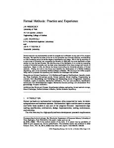
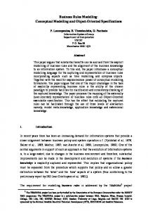
explicitly to organizational objectives and inter-actor relationships. The i* notation consists of two main modelling components: the Strategic Dependency Model (SD) and the Strategic Rationale Model (SR). The SD and SR models are graphical representations of the dependencies between actors and internal intentional characteristics of actors respectively. A SD model is a graph consisting of nodes and links among the nodes. Each node represents an actor, and each link between the actors represents how one actor (depender) depends on another (dependee) for something in order to accomplish a goal or task. The object around which the dependency relationship centres is called the dependum. An SD model represents goals, task, resource, and soft goal dependencies between actors. The first three of these dependency types are relatively straightforward to understand (an actor depends on another to fulfill a goal, execute a task and supply a resource, respectively). Softgoals are effectively nonfunctional requirements, i.e., statements of objectives that the target system should eventually meet. The SR model provides a more detailed level of modelling by looking ”inside” actors to model internal intentional relationships. As an example, consider a simplified version of the wellknown meeting scheduler scenario [11, 16, 17]. This example will be used to illustrate both the i* notation and our proposed methodology for transforming i* models into Z specifications. The SD modelling process (see Figure 1) begins with identifying the actors involved with the meeting scheduling system and their mutual dependency relationships. The MeetingInitiator agent depends on Participant agents to achieve its AttendsMeeting goal. The MeetingInitiator’s dependency on the MeetingScheduler to schedule a meeting can be modeled as a goal dependency MeetingBeScheduled. The resource dependency Agreement and task dependency EnterAvailDates are examples of other kinds of dependencies between actors. In the SR model (see Figure 2) intentional elements like goals, tasks, resources, and softgoals appear not only as ex-
Figure 1. The Strategic Dependency Model ternal dependencies, but also as internal elements which are connected by task-decomposition links and means-ends relationships. For example, the Participant has an internal task to ParticipateInMeeting. This task can be performed by subtasks AttendMeeting and ArrangeMeeting (these are related to the parent task via task decomposition links). For the MeetingInitiator, the goal of MeetingBeScheduled is an internal goal. In the case of Participant, the internal tasks FindAgreeableDateUsingScheduler and FindAgreeableDateByTalkingToInitiator are alternative means to achieve the goal Agreeable (Meeting, Date). How the alternatives contribute to softgoals is also represented. These are represented as means-ends link relationships. The SR model thus provides a way of modelling stakeholder interests, how they might be met, and the stakeholders’ evaluation of various alternatives with respect to their interests. Several proposals exist for integrating i* modelling with late-phase requirements analysis and the downstream stages of the software life-cycle. The TROPOS methodology [4] explores how i* models might be refined to form the basis for late-phase requirements specifications, and subsequently architecture specifications. The i* notation alone is not adequate for representing the level of detail necessary for late-phase requirements specifications. To address this, formal languages such as Formal Tropos [7] have been developed. An alternative approach has been to define methodologies for transforming i* models into agent programs in formal agent programming languages such as ConGOLOG [11]. Our thesis in this paper is that the Z formal notation and the i* modelling framework can function in a complementary and synergistic fashion and that a conceptual modelling
methodology that supports their co-evolution is of interest. Z [10] is a formal notation for computer systems and software specification based on set theory and first order predicate logic. This mature formal method is widely used both in theoretical investigations [1] and in practice [3]. The main elements of the Z notation are schemas which are used to specify states and operations for the modelling of systems. While Z can be used for early-phase requirements modelling, the necessary level of formalization, precision and detail, the lack of a diagrammatic notation to support the visualization of requirements and the inability to represent the intentional elements all suggest that an alternative notation such as i* might be better suited for this phase. Our proposal for a synergistic combination of i ∗ and Z offers several advantages: • i* and Z can be viewed as a pair of complementary representation languages that can be jointly brought to bear on the requirements engineering exercise. The i* notation permits us to make explicit the intentional aspects of the requirements specification, including an understanding of the organizational context of the proposed system, the alternatives that may be considered in making design decisions as well as the rationale behind these decisions (these latter features support process reengineering). The Z notation permits us to specify late-phase requirements with a degree of precision and formality that i* does not. • The i* notation allows us to represent and reason with softgoals (representations of non-functional requirements or objectives). • We propose a mapping from i* models into Z schemas
Figure 2. The Strategic Rationale Model that does not result in any information loss, nor the introduction of information extraneous to the original i* model (this is distinct from proposals such as the one involving mapping i* models to ConGolog agent programs [11], where aspects of the i* model are ignored in the translation). • The mapping of i* models to Z schemas enables the refinement of these schemas with additional information, such as invariant properties, fulfilment conditions etc. (note that these cannot be represented in the original i* model). • Current approaches to the use of formal methods in conjunction with i* models are unduly complies. Formal Tropos [7], for instance, is an intermediate language in which i* models must be defined before an eventual translation into a state machine model on which model checkers can be deployed to verify systems properties (the process also assumes a significant amount of refinement of the original model with additional information). Existing tool support for Z, on the other hand, allows analysis of specifications without any of this additional effort. In Section 2, below, we presented the mapping between i* models and Z schemas. In Section 3, we present an example of such a mapping. The example is specially interesting on account of the pointers we provide on how an initial set of Z schemas obtained from an i* model might be refined in useful ways. This paper may be viewed as a first step in defining a complete methodology for supporting the coevolution of i* models and Z specifications.
2 Mapping i∗ into Z 2.1 Mapping a general SD model into Z All elements (actors and dependencies) of a SD model differ in names. For describing their names in the Z notation we introduce the basic type (given set) NAME. Given an SD model, one can refer to distinct subsets of NAME. The subset all actors contains the names of all actors while the subset all depend contains the names of all dependencies in the SD model. [NAME] all actors, all depend : P 1 NAME It is necessary to mention that names of internal intentional elements of a SR model are also members of the given set NAME but do not belong to subset all depend. Formalization of these internal elements is considered later in the paper. Both SD and SR models provide a description of the intentional relationships among actors of a process and do not directly address the dynamics of this process. But exactly the dynamics are the most important for process or system specification. To reflect it, we use the fact that all dependencies in SD and internal elements in SR are realized dynamically: a goal is achieved, task is performed or resource becomes available. We consider different states of the dependencies (elements) before and after realization using the following free type definition:
STATE ::= inapplicable | unresolved | fulfilled | violated | satisficed | denied | undetermined State inapplicable is held before the creation of a new instance of a dependency (element). State unresolved conforms to a dependency (element) after the creation but before realization and all other states are conforming to a dependency (element) after realization. The dependency (element) is in state fulfilled if realization is successful and in state violated if realization is unsuccessful. With the idea of keeping uniform terminology with other researchers (e.g., [5]) in the area, for softgoals we use two states satisficed and denied. The last state undetermined can also be used only for a softgoal. Softgoals are often identified with quality criteria and sometimes it is impossible to conclude immediately after realization whether a quality criterion is satisfied. It means that it may not be clear whether the realization had been successful or not. In this case we consider the softgoal is in the undetermined state. The state of a whole SD model is a collection of states of all dependencies for this SD model that is reflected in SD schema1 : SD SD state : NAME → � STATE dom SD state = all depend Thus, the realization of a dependency changes its state and at the same time changes a state of the whole SD model. Each SD dependency or SR element has its own specific features and differs first in types and degrees. TYPE ::= goal | softgoal | task | resource | ISA DEGREE ::= open | committed | critical In contrast to other values, the ISA type does not represent a dependency. It means that one actor can be considered as a special instance of other actor. Since, ISA is a relationship between two actors it is convenient for us to consider them together as a different values of TYPE. All other values of free type definitions TYPE and DEGREE are standard for the i∗ framework. All the dependencies in SD (as well as every element in SR model - see the next section of the paper)are described by its own schema. A general structure of SD dependencies (external between actors) varies from a general structure of SR elements (internal inside actors) but at the same time they have some common patterns. That is why we use the following steps of formalization, creating consecutively: • ΦDepend schema which describes a common pattern of SD dependencies and SR elements; 1 All schemas in this paper were checked using the ZTC type-checker package [8].
• SDependency schema which describes a general structure of all the SD dependencies and includes ΦDepend schema as one of the component part; • A detailed schema for every SD dependency using SDependency schema as a basis. Common patterns for SD dependencies and SR elements are represented in ΦDepend schema. Here, Φ is a part of the schema name, not an operator. It is just a naming convention used to indicate a partial (incomplete) specification [2]. ΦDepend dependum : NAME type : TYPE degree : DEGREE result! : STATE result! �= unresolved result! = satisficed ∨ result! = denied ∨ result! = undetermined ⇒ type = softgoal Except for the above-mentioned type and degree, specific features of every dependency are its name (dependum) and resulting state, which is represented by the output variable result!. The first line of the predicate part of ΦDepend describes the fact that the resulting state cannot be unresolved. The second line of the predicate part of ΦDepend reflects that the resulting state can take the satisficed, denied or undetermined value only for softgoals. The following SDependency schema is a result of oneto-one mapping of the general structure of a SD dependency into the Z notation. This schema is an operation schema and changes the state of the SD model (∆SD). SDependency schema includes the components ΦDepend schema as well as names of actors (depender and dependee) which are linked by the dependency. While, this schema represents a general structure, its name, type, degree and names of actors are not specified. It could be done later on during the consideration of an i ∗ model for a specific example. SDependency ∆SD ΦDepend depender, dependee : NAME dependum ∈ all depend depender ∈ all actors dependee ∈ all actors SD state� = SD state ⊕ {dependum �→ result!} The most significant information is contained in the last line of the predicate part of this schema, which describes how the realization of the dependency changes the state of the SD model. Using the override operator ⊕ shows that
the value of the SD model’s state function SD state � after the dependency realization differs from its value SD state before the realization only in the part of the considered dependency and coincides for all other dependencies.
2.2 Mapping a general SR model into Z
For convenience, we allocate all conditions connected with links into a separate schema Link. This schema includes: • names of internal (inside the actor) elements int components which are linked with the considered element;
Our approach of mapping a SR model into the Z notation is similar to the approach for SD diagrams which were considered in the last section. The mapping consists in consecutively creating:
• names of external (from SD model) dependencies ext components which are linked with the considered element;
• Actor schema which describes a general structure of all the actors in SR diagrams;
• names of elements which give positive (contrib p) and negative (contrib m) contribution to the softgoals.
• AElement schema which describes a general structure of all the SR internal intentional elements and includes ΦDepend schema as one of the component part; • A detailed schema for every actor in the specific SR model using Actor schema as a basis; • A detailed schema for every internal element of every actor using AElement schema as a basis. The following schema describes a general structure of all the actors. An actor is characterized by his name actor name, set actor element of names of all internal elements, and state function actor state. Actor actor name : NAME actor element : P1 NAME actor state : NAME → � STATE actor name ∈ all actors dom actor state = actor element The actor state function is similar to the SD model’s state function SD state � and represents a collection of states of all internal elements of the actor. For formalizing a general structure of all SR elements, we need to introduce a new free type, which describes possible types of links between the elements. LINK TYPE ::= NA | task decomp | means ends | contrib Type NA (Non-Applicable) is used for elements which have no means for attaining them and have no components. Type task decomp represents task decomposition links. Types means ends and contrib describe meansends links. Type means ends is used for Goal-Task, TaskTask, Resource-Task, and Goal-Goal links. Type contrib represents special kinds of means-ends links for softgoal (Softgoal-Task and Softgoal-Softgoal links).
• type of the link;
Link ΦDepend int components, ext components : P NAME contrib p, contrib m : P NAME link : LINK TYPE link = task decomp ⇒ type = task link = contrib ⇒ type = softgoal contrib p ∪ contrib m �= ∅ ⇒ link = contrib ∧
contrib p, contrib m� partitions int components ext components �= ∅ ⇒ link = task decomp link = NA ⇔ cint components ∪ ext components = ∅ The predicate part describes the following constraints between types of links and types of elements: • Task decomposition links are used only for tasks; • Positive or negative contribution is possible only for softgoals; • Only task decomposition links are used for connection with external components. The following schema describes a general structure of all the SR internal elements. This operational schema changes the state of the general model of an actor (∆Actor). Similarly SDependency schema, AElement one includes as components ΦDepend schema. Inclusion of Link schema brings all the information concerning links between the elements. AElement ∆Actor Link dependum ∈ actor element int components ⊂ actor element ext components ⊆ all depend actor name� = actor name actor element � = actor element actor state� = actor state ⊕ {dependum �→ result!}
The predicate part of AElement schema formalizes the changes of Actor schema under the realization of the internal element. Only one component of Actor schema namely the actor’s state function actor state � is changed. Similar to the SD model’s state function SD state, the difference between values of actor state before and after the element realization exists only in the state of the considered element.
3 Mapping a specific i∗ model into Z: an example 3.1 Mapping the SD model Consider the example of mapping the i ∗ model into Z for the meeting scheduling system (see above Section 1). The SD model of the meeting scheduling system includes three actors (initiator, scheduler, and participant) and six dependencies (scheduled, date range, avail dates, proposed date, agreement, and attend). First of all it is necessary to describe their names in Z using the following axiomatic definition: initiator, scheduler, participant : NAME scheduled, date range, avail dates, proposed date, agreement, attend : NAME all actors = {initiator, scheduler, participant} all depend = {scheduled, date range, avail dates, proposed date, agreement, attend} The next step is to create six Z schemas (Scheduled, DateRange, AvailDates, ProposedDate, Agreement, and Attend) for each of six dependencies using Sdependency schema as a basis. In other words, we use inclusion of Sdependency schema and then additionally specify the following information: the names of the dependum, depender and dependee, the type and the degree of the dependency. As an example, consider DateRange schema which describes the following task dependency - the scheduler expects the meeting initiator to enter the data range. DateRange SDependency dependum = date range depender = scheduler dependee = initiator type = task degree = committed Line dependum = date range shows the name of the dependency. It is a task dependency so type = task. The scheduler depends on the meeting initiator so depender = scheduler and dependee = initiator. The importance of
the dependency is not marked in the SD diagram hence we consider degree = committed. Thus, DateRange schema corresponds to the date range dependency. It is intuitively obvious because of the similarity of names (we use this similarity only for clarity purpose). The formal correspondence between schemas and dependencies is established by using variable dependum inside the schemas without explicitly using the names of schemas. The formal rule of correspondence is described below: correspond : NAME → � SDependency dom correspond = all depend ∀ x : NAME | x ∈ all depend • (correspond(x)).dependum = x The schemas for all the other dependencies are similar to DateRange schema so we present only one of them without comments. AvailDates SDependency dependum = avail dates depender = scheduler dependee = participant type = task degree = committed
3.2 Mapping the SR model The first step of formalization of the SR model in Z is creating Z schemas Initiator, Scheduler, and Participant for each actor using Actor schema as the basis. In such schema we specify the name of the actor and names of all the internal elements of this actor. For example, consider the SR diagram of the meeting scheduling system (see above Section 1) initiator actor has four internal elements. We reflect it in the following Z schema: Initiator Actor org meeting, meeting be sch, low effort, let scheduler : NAME actor name = initiator actor element = {org meeting, meeting be sch, low effort, let scheduler}
The schemas for scheduler and participant actors are similar:
Scheduler Actor schedule, obt avail, obt agreement, slot, merge : NAME actor name = scheduler actor element = {schedule, obt avail, obt agreement, slot, merge} Participant Actor participate, attend, arrange, agreeable, friendly, using sched, talking init, agree date : NAME actor name = participant actor element = {participate, attend, arrange, agreeable, friendly, using sched, talking init, agree date} The next step is the creation of Z schemas for all the internal elements using AElement schema as the basis. In this way, we need to create seventeen schemas - four for internal elements of initiator actor, five for scheduler actor, and eight for participant actor. It is necessary to specify the name of the dependee, the type and the degree of the element (similar external dependencies) but also the kind of the link and names of external and internal components of the considered element. We are describing an example (without comments) of two internal elements using sched and friendly of participant actor. UsingSched AElement Participant dependum = using sched type = task degree = committed int components = {agree date} ext components = {avail dates} link = task decomp Friendly AElement Participant dependum = friendly type = softgoal degree = committed int components = {using sched, talking init} contrib p = {talking init} contrib m = {using sched} ext components = ∅ link = contrib
3.3 Refinement The benefits of using concepts introduced in Section 2.1 state function SD state becomes apparent on the step of the information refinement. The task of refining with additional information from the existing SD and SR models requires a separate investigation and is beyond the scope of this paper. We are providing essence of possible approaches with two examples. The first example is concerned with the data exchange between actors. The Scheduler actor receives and sends information about the possible dates of the meeting. We use the basic type DATE to describe this information and introduce more detailed schema Scheduler1 which contains all these dates. [DATE] Scheduler1 Scheduler d range, d avail : P DATE d propos : DATE d avail ⊆ d range d propos ∈ d avail This gives us an opportunity to create a more detailed schema for dependency AvailDates (now AvailDates1). First of all, intermediate (partial) schema ΦAvail1 shows that Scheduler1 changes but only for d avail component. ΦAvail1 == ∆Scheduler1 ∧ (ΞScheduler1 \ (d avail)) AvailDates1 schema includes ΦAvail1 and describes the way now d avail changes. AvailDates1 AvailDates ΦAvail1 input? : P DATE SD state(date range) = fulfilled d avail = ∅ ⇒ d avail � = input? d avail �= ∅ ⇒ d avail � = d avail ∩ input? This change is possible only if the previous dependency date range is realized (fulfilled) successfully. The scheduler collects data from several participants. Hence the condition of date range realization is the selection of available dates which are suitable for all the participants. The second example is concerning temporal features and operators. The state function SD state represents the snapshot state of the system. To describe the behaviour of the
system in time, consider all the possible sequences of system states SDscenarios : P(seq SD) SDfuture, SDpast : SD → � P(seq SD) ran SDfuture ∪ ran SDpast ⊆ P SDscenarios ∀ s : SD • SDfuture(s) = {f : seq SD | head f = s} ∧ SDpast(s) = {p : seq SD | last p = s} For each state function s consider all the behaviours Sdfuture which are started in s (the future of the system) and behaviours SDpast that are finished in s (the past of the system). Now we can formalize all the main temporary operators such as sometimes in the past, always in the past, sometimes in the future, always in the future, etc., which are used in different techniques of requirements engineering, for example, KAOS [6], Formal Tropos [7]. Thus, the operator 2 φ always in the future [7] for state s can be modelled as ∀ c : seq SD; st : SD | c ∈ SDfuture(s) ∧ st� ⊆ c • φ Correspondingly, the operator ◦ φ next state for state s can be modelled as ∀ c : seq SD; st : SD | c ∈ SDfuture(s) ∧ st = c(2) • φ and the operator ♦ φ eventually in the future for state s can be modelled as ∀ c : seq SD | c ∈ SDfuture(s) • ∃ st : SD | st� ⊆ c • φ If we consider a system which demands special timing requirements (for example, a concurrent real-time reactive system), then it is possible to use special extensions of Z like Timed Communicating Object Z (TCOZ) [9] designed for modelling real-time.
4 Conclusions Our proposal in this paper is that the Z formal notation and the i* modelling framework can function in a complementary and synergistic fashion. A conceptual modelling methodology that supports their co-evolution is of interest. This approach makes use of the advantages of i ∗ for the early-phase of requirements engineering (visualization of requirements, possibility of easy modifications, etc.) and then continues with the specification of requirements in Z. The Z notation permits us to specify late-phase requirements with a degree of precision and formality that i* does not. We have considered in detail the first step of the methodology - one-to-one mapping i ∗ diagrams into the Z notation. It allows us to formalize i ∗ diagrams without adding
or suppressing information. The next step in the approach is the refinement of the methodology by considering additional information from the i ∗ diagrams. This information (invariant properties, fulfilment conditions, etc.) can be easily incorporated into the Z schemas and allows us to consider the dynamic changes in the system states. The complete methodology of refinement with additional information from the existing SD and SR models requires a separate investigation and forms the main direction of our future research.
References [1] Bert, D., Bowen, J. P., King, S., Wald´en, M., editors. ZB2003: Formal Specification and Development in Z and B, 3rd International Conference of B and Z Users, Turku, Finland, 4-6 June 2003. Springer-Verlag, LNCS 2651, 2003. ISBN 3-540-40253-5. [2] Bowen, J. P. Formal Specification and Documentation Using Z: A Case Study Approach. International Thomson Computer Press, 1996. [3] Bowen, J. P., Hinchey, M. G., editors. IndustrialStrength Formal Methods in Practice. Springer-Verlag, FACIT series, 1999. [4] J. Castro, M. Kolp and J. Mylopoulos. Towards Requirements-Driven Information Systems Engineering: The Tropos Project. To appear in Information Systems, Elsevier, Amsterdam, The Netherlands, 2002. [5] Chung, L., Nixon, B. A., Yu, E., Mylopoulos J. Non-Functional Requirements in Software Engineering. Kluwer Academic Publishers, 2000. [6] Dardenne, A., van Lamsweerde, A., Fickas, S. GoalDirected Requirements Acquisition. Science of Computer Programming, Vol. 20, North Holland, 1993, pp. 3-50. [7] Fuxman, A., Pistore, M., Mylopoulos, J., Traverso, P. Model checking early requirements specifications in Tropos. Proceedings of Fifth IEEE International Symposium on Requirements Engineering, Toronto, Canada, August 27-31, 2001, pp. 174 -181. [8] Jia, X. ZTC: A Type Checker for Z Notation. User’s Guide. Version 2.03, August 1998. Division of Software Engineering, School of Computer Science, Telecommunication, and Information Systems, DePaul University, USA, 1998. [9] Mahony, B., Dong, J S. Timed Communicating Object Z. IEEE Transactions on Software Engineering, Vol. 26, Issue 2, February 2000, pp. 150–177.
[10] Spivey, J. M. The Z Notation: A Reference Manual. Prentice Hall International Series in Computer Science, 2nd edition, 1992. [11] Wang, X., Lesprance, y. Agent-Oriented Requirements Engineering Using ConGolog and i*. Proceedings of 3rd International Bi-Conference Workshop Agent-Oriented Information Systems (AOIS2001), Berlin, Germany, 2001, pp. 59-78. [12] Yu, E., Mylopoulos, J. An Actor Dependency Model of Organizational Work - with Application to Business Process Reengineering. Proceedings of Conference on Organizational Computing Systems, Milpitas, California, USA, Nov. 1-4, 1993, pp. 258-268. [13] Yu, E., Mylopoulos, J. Understanding ”Why” in Software Process Modelling, Analysis, and Design. Proceedings of 16th International Conference on Software Engineering, Sorrento, Italy, May 16-21, 1994, pp. 159168. [14] Yu, E. Towards Modelling Strategic Actor Relationships for Information Systems Development – With Examples from Business Process Reengineering. Proceedings of 4th Workshop on Information Technologies and Systems, Vancouver, B.C., Canada, December 17-18, 1994, pp. 21-28. [15] Yu, E. Modelling Strategic Relationships for Process Reengineering. PhD Thesis, Graduate Department of Computer Science, University of Toronto, Toronto, Canada, 1995, pp. 124. [16] Yu, E. Towards Modelling and Reasoning Support for Early-Phase Requirements Engineering. Proceedings of 3rd IEEE International Symposium on Requirements Engineering, Washington D.C., USA, January 68, 1997, pp. 226-235. [17] Yu, E. Agent Orientation as a Modelling Paradigm. Wirtschaftsinformatik, April 2001, pp. 123-132.