full metal jacket bullet consists of the brass shell and solid lead stuff presented as two separate parts that are in contact interaction with each other. In the contact ...
Proceedings of the 5th WSEAS Int. Conf. on SIMULATION, MODELING AND OPTIMIZATION, Corfu, Greece, August 17-19, 2005 (pp427-432)
Combining mezzo- and macro-mechanical approaches in a computational model of a ballistic impact upon textile targets RIMANTAS BARAUSKAS System Analysis Department Kaunas University of Technology Studentu 50-407, 51368 Kaunas LITHUANIA
Abstract: A finite element model of the shooting test against the paraaramyde Twaron multi-layer textiles package structure has been developed in LSDYNA. The bullet has been considered as a deformable body in contact with the fabric package presented by interwoven yarn structure. The simplification of the model has been achieved by presenting the multifilament yarns by thin shell elements the thickness of which represents the real thickness of yarns as it can be measured in the weave. The zones of the fabric remote from the point of impact have been presented as a roughly meshed uniform thin shell model. The junction between the two types of zones of the fabric has been performed by means of the tie constraint and by proper adjustment of material parameters ensuring the same speeds of the wave propagation in the interwoven yarn structure and in the uniform shell. Physical and numerical experiments have been performed in order to identify the material model parameters. Key-Words: high-velocity impact, textiles, finite elements, LSDYNA.
1 Introduction The results obtained during the investigation of multi-layer textile packages designated for the clothes ensuring the ballistic protection imply that the protection level is defined by the structure and properties of multi-filament yarns, weave type of a fabric, number of layers and interconnection technique of a textile package, etc.,[1]. Quick rise and variety of new materials on the market [2] promotes the further theoretical and experimental investigations of textiles packages by establishing their regularities and relationships. The design of the structure of a multi-layer package could be significantly facilitated by the deeper understanding
of the behavior of a single textiles layer and interaction of several layers with a bullet that can be carried out by computer simulations. During the last decade numerous studies have been carried out on the ballistic impact upon high strength fabric structures [3,4,5,6]. The problems including flexible textile structures such as clothes are very difficult to represent by equivalent anisotropic solid models as after the failure of yarns the geometry of the model becomes very complex. In [7] a computational model in LSDYNA has been presented that enabled to consider the geometry of the weave by using shell elements. Numerous approaches have been presented where yarns of a weave
were modeled by using 3D solid elements [6,8,9]. The aim of this work was to develop a computational model of interaction of a deformable projectile(bullet) against a multilayer textile package enabling to simulate shooting experiments performed in order to test the ballistic strength of textile body armor. Comparisons with the experimental results have been carried out in order to determine the dynamic parameters of the material behavior and to validate the model.
2
The model of a fabric package
2.1
Mezzo-mechanical model of a woven patch
A fabric is made of yarns of certain linear density woven together. Each yarn consists of filaments the number of which can vary from several hundred to several thousand. The computational model of a fabric at the level of filaments is rather unrealistic because of limited computer resource, so we develop a mezzo-mechanical model in which a yarn has been considered as primary component comprising a fabric. The properties of an individual yarn are defined empirically by making several assumptions. It s commonly accepted that the cross-section of
Proceedings of the 5th WSEAS Int. Conf. on SIMULATION, MODELING AND OPTIMIZATION, Corfu, Greece, August 17-19, 2005 (pp427-432)
a free yarn not interwoven into a textiles is close to a circle made of cross-sections of a certain number of individual filaments, Fig.1,a. In a fabric the
Fig.1: Circular cross-section of a free yarn (a); cross-section of an interwoven yarn (b); cross-section of an interwoven yarn approximated by rectangular crosssections of four shell elements (c)
yarns are being compressed because of forces acting in overlapping areas. As a result, the geometry of the cross-section of each yarn is being changed depending upon the constitution of the yarn, its density, its type and technological parameters of the weave. We assume it to be close to the combination of two circular segments (Fig.1,b) the dimensions of which are calculated basing upon the given characteristics of the textiles. E.g., the height and length of the Twaron yarns in the textiles CT709 are b=0.952mm and h=0.15mm. The cross-section of a yarn interwoven into a fabric has been modeled as shown in Fig.1,c. As its height is much smaller than the width we used four shell elements the thickness of which was selected in order to fit two circular segments form. The bending stiffness of the yarn we assumed to be negligible. In order to eliminate the bending stiffness in LSDYNA, we used the Hughes-Liu shell with single integration point through the thickness of the element. The technique of obtaining the model of a woven yarn patch has been described in our recent work [7].
2.2
the dimension of 12 fabric layers model may reach ~108 nodes. In order to obtain smaller models, the macro-mechanical approach is being used and the zones of the fabric remote from the interaction zone are modelled by means of shell(membrane) elements. The finely and roughly meshed zones are connected by using the *CONSTRAINEED_TIEBREAK constraint in LSDYNA. We prohibit the failure of the constraint by using very large failure strain values and no-failure material model for the yarns neighbouring to the membrane model. The uniform membrane-type surrounding of the woven patch cannot be expected to present an identical dynamic behaviour as the woven yarn structure. However, a satisfactory approximation is possible provided that the thickness of the membrane elements and their elastic material properties are selected as follows. Two models of the fabric layer with different dimensions of the woven patch are built. The linear dimension of the patch must be at least twice greater than the diameter of the zone at which the failure of yarns may take place. We have to select the equivalent thickness of the membrane and its stiffness and shear modules in order to make the overall response of the two models close to each other as much as possible. The numerical tests are performed for the bullet impact speed 270m/s.
a
Macro-mechanical model of a layer
The zone of the fabric proximately taking place in the contact interaction for a 9mm bullet comprises only about 10-30mm in diameter. However, in order to present properly the dynamics of the interaction process much larger pieces of a fabric should be modeled. The duration of the interaction process is generally conceived as the time from the beginning of the impact until it reaches zero velocity embedded into the multilayer. During this time, the elastic wave propagating from the point of impact travels much larger distances, so the linear dimension of the fabric being modeled should be ~200-400mm. Unfortunately, the weave step being about 1mm, such “woven” models are prohibitive because of the huge dimensionality. As an example,
b Fig.2. Propagation of the longitudinal component of the impact wave accros the tie boundary: numbers of nodes along the wave propagation direction (a) and time laws of longitudinal displacements of nodes (b)
Proceedings of the 5th WSEAS Int. Conf. on SIMULATION, MODELING AND OPTIMIZATION, Corfu, Greece, August 17-19, 2005 (pp427-432)
a
b
c
d Fig.3. Transverse wave propagation: a,b– model 30x30 yarns woven patch; c,d - model 10x10 yarns woven patch; b,d – z-displacement time laws of nodes indicated in figures (a) and (c)
The test results of the wave propagation across the tie constraint line are presented in Fig.2. The longitudinal and transverse components of the wave have been analyzed. The impact of the bullet upon the fabric causes the displacements of the surrounding nodes towards the center of impact. The longitudinal displacement wave propagates much faster than the transverse displacement wave and travels far into the membrane region of the model during the time of impact interaction. The stiffness properties of the membrane have to ensure the same speed of the wave propagation in the woven and membrane When analyzing the transverse wave propagation we established the thickness of the membrane equal to the maximum thickness of the yarn in the weave (in our case 1.5mm) and very small values of the shear modulus of the membrane. Numerical tests of the performance of the two models are presented in Fig.3 which presents the general view of the model at two time moments and time laws of z-displacements of two nodes distances of which from the center of impact are equal in both models, Fig.3,b,d. The analysis of the results illustrates the similarities and slight differences between the results obtained by using the two models. The failure of the fabric at the impact zone is presented identically by in both models. The impact wave shape is slightly distorted as it leaves the woven zone, however, the time laws of the z-displacements of the nodes at the edge of the smaller woven zone are close to each other in both models. Consequently, for time intervals necessary for analyzing 270m/s ballistic interaction the model containing 10 yarns per half of the woven patch could be regarded as satisfactory.
2.2
Interaction model
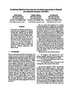
The developed model of a single fabric layer has been used for the analysis of the ballistic impact of a bullet upon the multilayer textiles package. The model enables to simulate the failure caused by impact loads similar to the loads to which the fabric is subjected during the shot. Two different bullet models have been used in this analysis. The finite element model of the 9mm full metal jacket bullet consists of the brass shell and solid lead stuff presented as two separate parts that are in contact interaction with each other. In the contact interaction model the brass shell interacts with the multilayer textile package. In some calculations the finite element model of the lead bullet BALLE 22 has been used. The view of the contact model symmetrical with respect to xOz
Proceedings of the 5th WSEAS Int. Conf. on SIMULATION, MODELING AND OPTIMIZATION, Corfu, Greece, August 17-19, 2005 (pp427-432)
Fig.4. The geometry of the contact interaction between fabric package and the deformable bullet
and yOz planes is presented in Fig.4. The materials taking place in the contact interaction are brass, lead and paraarmyde Twaron fabric. The brass and lead are elastic-plastic materials, and Twaron material is assumed to be perfectly elastic up to its failure limit. As during the deformation volumetric, as well as, deviatoric strains and stresses are important, all the materials are presented by using the *MAT_PLASTIC_KINEMATIC. At ~300m/s impact velocity the problem is classified as high velocity contact-impact interaction problem where the yield stress value is assumed to be dependent upon the strain rate in accordance with the Symonds-Couper material model [10]: 1 ε� p σY = σY 0 1+ , C
(1)
where σ Y , σ Y 0 - yield stress limits of the material defined with and without the influence of strain rate ε� ; C and p - constants.
3
• The use of the “macro-mechanical” concept for presenting the “infinite” fabric environment of the woven patch; • Unknown dynamic values of the material parameters. At 300m/s impact velocity static relationship of yield stress against the plastic strain does not adequately describe the real physical phenomena. This circumstance is important for all materials participating in contact interaction – paaramyde, lead and brass. Though we used simplest model (1) to modify the yield stress value by taking into account the strain rate, a series of physical and numerical experiments is necessary in order to obtain physically adequate values C and p, as well as, some other parameters describing the behavior of the material. Also the selection of proper hardening model may appear as crucial for obtaining adequate results. We assume the elasticity and shear modules, yield stress, tangential modulus and mass density of each material as known. Values C and p in relation (1) and hardening hypothesis (kinematical, isotropic or the combination of the two) can be assumed as parameters the values of which need to be determined in order to achieve the adequacy of simulation results to reality. The following experiments have been made: • Shot of the lead bullet Balle22 against the 10mm thickness lead plate; • Shot of a 9mm full metal jacket bullet consisting of brass shell and lead stuff against 10mm thickness lead plate; • Shot a bullet against a multi-layer textile package.
Model validation and results
3.1 General approach The adequacy of the obtained results to reality is a highly important question in any simulation. In the case of the system under consideration two reasons which may cause an inadequacy of the results can be mentioned: • The “mezzo-mechanical” concept of the model, where the multi-filament structure of a thread is highly simplified;
3.2 Determining the lead material parameters As an experiment for validation of lead material parameters we used numerical and physical experiments of shooting the lead bullet into 10mm thickness lead plate in order to have only one unknown material, [11]. The values of elasticity modulus E, Puasson’s ratio PR and mass density RO were considered as given above. The coefficients C (SRC)and p (SRP) of relationship (1), as well as, tangent modulus ETAN and parameter BETA were selected in order to obtain the simulation results close to experimental ones. The value of ETAN is known as 5.43E+07, however, our analysis demonstrated that the diminished value 1.5E+07 provides the adequate behavior of the model. The explanation for this may be that the contacting bodies are hot (the bullet is hot because of heat exchange in the rifle, and also the
Proceedings of the 5th WSEAS Int. Conf. on SIMULATION, MODELING AND OPTIMIZATION, Corfu, Greece, August 17-19, 2005 (pp427-432)
contact interaction releases considerable amounts of heat). Parameter BETA