is prone to many backtracks, which can lead to high execution times. In our hybrid test generator, we use a simulation-based approach for state justi cation in ...
Proceedings of the ACM/IEEE Design Automation Conference, pp. 183-188, June 1995
Combining Deterministic and Genetic Approaches for Sequential Circuit Test Generation 3 Elizabeth M. Rudnick
Janak H. Patel
Motorola, Incorporated Austin, TX
Center for Reliable & High-Performance Computing University of Illinois, Urbana, IL
Abstract|A hybrid sequential circuit test generator is described which combines deterministic algorithms for fault excitation and propagation with genetic algorithms for state justi cation. Deterministic procedures for state justi cation are used if the genetic approach is unsuccessful, to allow for identi cation of untestable faults and to improve the fault coverage. High fault coverages were obtained for the ISCAS89 benchmark circuits and several additional circuits, and in many cases the results are better than those for purely deterministic approaches. I.
INTRODUCTION
Sequential circuit test generation using deterministic algorithms is highly complex and time consuming [1-7]. Each target fault must be excited and the fault e�ects propagated to a primary output (PO); the required state must then be justi ed, and state justi cation is typically done by reverse time processing. Backtracing is a critical step and is used to determine the component input values required to obtain a particular output value. Handling components other than simple gates is especially di�cult because of the backtracing step. Simulationbased test generation has been used to reduce the complexity of test generation. In a simulation-based approach, processing occurs in the forward direction only, and no backtracing is required. Therefore, complex component types are handled more easily. Candidate tests are generated, and a logic or fault simulator is used to select the best test to apply in a given time frame. Several faults are typically targeted simultaneously. Seshu and Freeman [8] rst proposed simulation-based test generation, and several simulation-based test generators have since been developed using random [9], weighted random [10-12], and mutation-based [13, 14] pattern generators. Simulation-based test generators which use genetic algorithms (GAs) to generate candidate tests have also been developed [15-18]; very high fault coverages and fast execution times have been reported for several circuits. 3 This
research was supported by the Semiconductor Research Corporation under Contract SRC 94-DP-109.
A comparison of results for deterministic and GA-based test generators shows that each approach has its own merits. For some circuits, deterministic test generators provide higher fault coverages, while for other circuits, GA-based test generators provide higher fault coverages. The simulationbased approach is particularly well suited for data-dominant circuits, while deterministic test generators are more e�ective for control-dominant circuits. Untestable faults can be identi ed by using deterministic algorithms, but signi cant speedups can be obtained with the genetic approach. Hence, combining the two approaches could be bene cial. A straightforward solution would be to start with the GA-based test generator and then to use a deterministic test generator to improve the fault coverage and to identify untestable faults. Saab's hybrid test generator [19] switches from simulation-based to deterministic test generation when a xed number of test vectors are generated without improving the fault coverage; simulation-based test generation resumes after a test sequence is obtained from the deterministic procedure. We will explore a di�erent approach which uses deterministic algorithms for fault excitation and propagation, and a GA for state justi cation. Individual faults in a circuit are targeted, as is normally done in deterministic test generators. Deterministic algorithms for combinational circuit test generation have proven to be more e�ective than genetic algorithms [17]. Higher fault coverages are obtained, and the execution time is signi cantly smaller. A hybrid test generator would then naturally include the deterministic algorithm for fault excitation and propagation within a single time frame. Since we have access to the HITEC [6] source code, we also chose to use the deterministic algorithms for fault propagation in successive time frames. State justi cation using deterministic algorithms is a much more di�cult problem, however, and is prone to many backtracks, which can lead to high execution times. In our hybrid test generator, we use a simulation-based approach for state justi cation in which candidate sequences evolve over several generations, as controlled by a GA. When a sequence which justi es the desired state is found, execution of the GA terminates. Deterministic procedures for state justi cation are used only if the genetic approach is unsuccessful. We begin with a brief description of GAs. An overview of our hybrid approach to test generation is given next, followed by a discussion of the application of GAs to state justi cation. Results are then presented in Section V for the ISCAS89 sequential benchmark circuits [20] and several synthesized circuits.
II.
GENETIC ALGORITHMS
The simple GA, as described by Goldberg [21], contains a population of strings, or individuals. Each string is an encoding of a solution to the problem at hand. Each individual has an associated tness, which gives an indication of the quality of the corresponding solution and thus depends on the application. The population is initialized with random strings, and the evolutionary processes of selection, crossover, and mutation are used to generate an entirely new population from the existing population. This process is repeated for m generations. To generate a new population from the existing one, two individuals are selected, with selection biased toward more highly t individuals. The two individuals are crossed to create two entirely new individuals, and each character in a new string is mutated with some small mutation probability p. The two new individuals are then placed in the new population, and this process continues until the new generation is entirely lled. At this point, the previous generation can be discarded. In our work, we use tournament selection without replacement and uniform crossover. In tournament selection without replacement, two individuals are randomly chosen and removed from the population, and the best is selected; the two individuals are not replaced into the original population until all other individuals have also been removed. In uniform crossover, characters from the two parents are swapped with probability 1/2 at each string position in generating the two o�spring. A crossover probability of 1 is used; i.e., the two parents are always crossed in generating the two o�spring. Also, a mutation probability of 1/64 is used. Because selection is biased toward more highly t individuals, the average tness is expected to increase from one generation to the next. However the best individual may appear in any generation, so we save the best individual found. III.
OVERVIEW
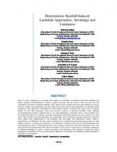
Test generation using our hybrid approach is illustrated in Fig. 1. An individual fault in the circuit is targeted. The fault is excited, and required values are backtraced to the primary inputs (PIs) and ip- ops. Next, the fault e�ects are propagated to a PO, either in the current time frame or in successive time frames. Again, required values are backtraced to the PIs and to ip- ops in time frame zero, in which the fault was excited. If any con icts are found during fault excitation and propagation, the test generator backtracks to a decision point and makes an alternative choice. Finally the required state in time frame zero is justi ed by using GAs. Several candidate sequences are simulated, starting from the last state reached after any previous tests have been applied. If a sequence is found which justi es the state, then the sequence is added to the test set, along with the vectors required for fault excitation and propagation. If a sequence cannot be found to justify the desired state, then backtracks are made in the fault propagation phase, and attempts are made to justify the new state. One drawback to this approach is that untestable faults cannot be identi ed. Even if a sequence exists which justi es a given state, the GA is not guaranteed to nd it. Therefore, deterministic algorithms for state justi cation are still required in a complete test generator. Hence, our overall approach to test
Fault Excitation and Propagation
PI 1 1 0 X 0 0 X 1 1 FF
PI 0 0 0 1 State 1 Justification X X 1 X FF
time frame (0) 1 1
s-a-0 X 1 0
time frame (-2)
PO PI X X 0 1 1 1/0 1/0 X X 0 0 X X FF FF PO
0 X X 1 FF
PI 1 0 1 1 0 0 X X 1 FF
time frame (1)
PO
0/1
FF time frame (-1)
PO
0 1 1 1 FF
Figure 1: Test generation using GA for state justi cation. generation includes both genetic and deterministic approaches for state justi cation, as indicated in Table I. The test generator makes several passes through the fault list, with di�erent conditions and time limits imposed in each pass. Faults are removed from the fault list once they are detected. After each pass, the user is prompted as to whether to continue with another pass, and execution terminates when the user responds negatively. In the rst pass through the fault list, state justi cation is performed using a GA. A time limit of one second per fault is imposed, which limits the number of backtracks in the deterministic fault propagation phase. A small population size of 64 is used, and the number of generations is limited to four to reduce the execution time. A sequence length of 21 x is used, where x is supplied by the user. Many of the testable faults are detected in this pass, but untestable faults are identi ed only if con icts are found without doing state justi cation. In the second pass through the fault list, GAs are again used for state justi cation, but the search space is expanded. In particular, the population size is increased to 128, the number of generations is increased to eight, and the sequence length is doubled. Also, the time limit is increased to 10 seconds per fault to enable more backtracking in the fault propagation phase.
Table I: TEST GENERATION APPROACH
Pass 1
State Justi cation Approach Conditions GA
2
GA
3
deterministic
1-second limit per fault population size = 64 4 generations sequence length = 1/2x 10-second limit per fault population size = 128 8 generations sequence length = x 100-second limit per fault
Finally, deterministic algorithms are used for state justi cation for any additional passes through the fault list. Required values at the ip- ops are backtraced to the PIs in previous time frames through reverse time processing. An untestable fault is identi ed when all possible choices at decision points prove unsuccessful in generating a test to detect the fault. The time limit per fault is increased to 100 seconds in the third pass and multiplied by ten in successive passes to expand the search space. In this manner, tests are generated for many of the testable faults by using the GA for state justi cation. The deterministic algorithms for state justi cation are used to identify untestable faults and to generate tests for hard-to-detect faults only. IV.
APPLICATION OF GA'S TO STATE JUSTIFICATION
In applying GAs to state justi cation, we use each string in the population to represent a candidate test sequence. A binary coding is used, and successive vectors in the sequence are placed in adjacent positions along the string. Sequences are evolved over several generations, with the tness of each individual being a measure of how closely the nal state reached matches the desired state. If any sequence is found which produces the desired state, the search is terminated, and the sequence is added to the test set, along with the fault excitation and propagation vectors. Otherwise, the GA runs to completion for a limited number of generations. The test sequence length used is typically a multiple of the sequential depth of the circuit. A.
Fitness Function
Since the tness of an individual sequence indicates how closely the state it produces matches the desired state, simulation is required. The presence of a particular fault may a�ect the state; thus, both good and faulty circuit simulations are required for an accurate result. If tests have already been added to the test set, then the current good circuit ip op values may already be known. However, the state is not known for the faulty circuit unless a faulty circuit simulation is performed using all previously generated test vectors. Instead of simulating the faulty circuit, we initialize the faulty circuit ip- ops to unknown values. Before the search is begun for a sequence to justify a required state, the desired good circuit state is compared to the current good circuit state, and the desired faulty circuit state is compared to the all-unknown state. (Note that separate values are maintained for the good and faulty circuits during the fault excitation and propagation phases.) If the states match, no justi cation is required. If the current state does not match the desired state, then several candidate sequences are simulated for both the good and faulty circuits. Fault injection is performed by modifying the circuit description, as is done in PROOFS [22]; eg., an ORgate is inserted to simulate a stuck-at-one fault, and the second input of the OR-gate is set to zero for the good circuit and one for the faulty circuit. The bitwise parallelism of the computer word is used, which allows 32 sequences to be simulated in parallel. Two bits are required to represent the three possible logic values: one, zero, and X (unknown). Thus, two computer
words are used at each node to simulate the good circuit, and two computer words are used at each node to simulate the faulty circuit. PI values are mapped from the sequences in the GA to the respective bit positions at the PI nodes. Simulation is done in an event-driven manner, with good and faulty circuit simulations done together. The test sequence length is set to a xed value, but the state is checked after each test vector is simulated to determine whether it matches the desired state. If it does, the search is terminated. Therefore, the length of the actual test sequence used may be less than the given value. However, for the purposes of the GA, the tness function measures how closely the nal state matches the desired state: 9 (# matching f lip f lops in good circuit) 10 1 + (# matching f lip f lops in f aulty circuit): 10 A ip- op is considered to match if it requires no particular value or if the desired and actual values are equal. If the states match in both the good and faulty circuits, then the tness will equal the number of ip- ops in the circuit. The two terms in the tness function correspond to the two goals of the GA: nding a state justi cation sequence for the good circuit and nding a state justi cation sequence for the faulty circuit. Unequal weights are used in order that the GA can be targeted to one goal at a time. When a GA has two or more goals, the optimum tness function does not necessarily weight the goals equally. If equal weights are used, the GA jumps back and forth among the goals, and none of the problems gets solved quickly. A heavy weighting of one goal ensures that the strings evolve steadily in one direction. Experiments on several circuits con rmed that the weights chosen work better than equal weights of 1/2. Squaring of the tness function has been used previously to amplify the di�erences between individuals [21]. Such a measure should be considered if a proportionate selection scheme is used, but since tournament selection is being used in our GA, this operation would have no e�ect on the result. f itness
B.
=
GA Parameters
Since 32 sequences can be evaluated in parallel, the population size should be a multiple of 32. Initially, we use a small population size of 64 to limit the execution time. We increase it to 128 in the second pass through the fault list, expanding the search space. The number of generations is initially limited to four, again to reduce the execution time. We increase the number of generations to eight in the second pass, when expanding the search space. Tournament selection and uniform crossover are used, since these schemes worked well in simulation-based test generation [18]. Crossover and mutation probabilities of one and 1/64, respectively, are used. Nonoverlapping generations are used, since exploration of the search space is paramount. V.
RESULTS
A hybrid test generator, GA-HITEC, was implemented using the existing HITEC [6] source code and 2700 additional
lines of C++ code. Tests were generated for several of the ISCAS89 sequential benchmark circuits [20] on a SUN SPARCstation 20 with 64 MB memory. Test generation results are shown in Table II. Results for HITEC are shown for comparison. The three lines of results for each circuit correspond to three passes through the fault list with time limits and parameter settings as shown in Table I for GA-HITEC. One exception is that a population size of 32 was used for passes one and two for circuit s35932 to speed up the execution. Test sequence lengths of four and eight times the sequential depth were used in passes one and two, respectively, for all circuits except s5378 and s35932. Test sequence lengths were one-quarter and onehalf the sequential depth for these circuits. Higher fault coverages might be obtained with longer test sequences, but the execution time would increase. HITEC also makes several passes through the fault list. The time and backtrack limits are initially set to one second and 10,000 backtracks, respectively, and they are multiplied by ten in each successive pass. Further improvements in fault coverage and untestable fault identi cation are possible for both GA-HITEC and HITEC if a fourth pass is made through the fault list using a time limit of 1000 seconds per fault; however, execution times would increase. The number of faults detected (Det), the number of test vectors generated (Vec), the total execution time, and the number of untestable faults identi ed (Unt) at the end of each pass are shown for both GA-HITEC and HITEC. For many circuits, more faults are detected by GA-HITEC than HITEC at the end of each of the rst two passes. In most cases, the GA-HITEC fault coverage at the end of the third pass is greater than or equal to that of HITEC. These results show that the GA is e�ective in searching for state justi cation sequences, especially when it is combined with the deterministic approach. In the rst two passes, GA-HITEC is able to make use of the current good circuit state, i.e., the state reached after all previous sequences in the test set have been applied. In contrast, HITEC always backtraces to a time frame in which all ip- ops are set to unknown (don't care) values. However, GA-HITEC is not a superset of HITEC. Although GA-HITEC uses the same algorithms as HITEC after the second pass, the HITEC fault coverage is sometimes higher after the third pass. For example, HITEC detects 34,898 faults in circuit s35932 after the third pass, while GA-HITEC detects only 34,862 faults. This discrepancy occurs because the algorithms used in HITEC are partially nondeterministic. Many of the faults are incidentally detected by the test sequences generated; these faults are identi ed by the fault simulator, and they are never targeted by the test generator. The fault coverage thus depends on the fault list ordering and the time limit imposed on each fault. While fewer untestable faults are generally identi ed in the rst two passes with GA-HITEC, approximately the same number are identi ed at the end of the third pass. Note that in some cases, such as circuit s832, HITEC declares some testable faults to be untestable. Comparison of execution times shows that GA-HITEC is faster for some circuits, while HITEC is faster for other circuits. GA-HITEC wastes time targeting untestable faults in the rst two passes, a result especially apparent for circuit s386. If these untestable faults can be
ltered out in advance, signi cant speedups can be obtained. The higher HITEC execution time for some circuits is due to the fact that HITEC has lower fault coverage for these circuits and is repeatedly targeting the same testable faults unsuccessfully. Results of running GA-HITEC on several circuits synthesized from high-level descriptions are shown in Table III. The Am2910 circuit is a 12-bit microprogram sequencer similar to the one described in [23]; div is a 16-bit divider which uses repeated subtraction to perform division; mult is a 16bit two's complement multiplier which uses a shift-and-add algorithm; and pcont2 is an 8-bit parallel controller used in DSP applications. Test sequence lengths of 24 and 48 were used in the rst two passes through the fault lists. For larger circuits, smaller test sequence lengths could be used and the GA parameters could be adjusted to speed up the execution, but lower fault coverages might then be obtained. Results for HITEC are shown for comparison. The two or three lines of results for each circuit correspond to the individual passes through the fault list. GA-HITEC yielded higher fault coverages than HITEC for all four circuits, and the GA-HITEC execution times were also smallest. VI.
CONCLUSIONS
Deterministic algorithms for fault excitation and propagation have been combined with a genetic algorithm for state justi cation in a new hybrid sequential circuit test generator, GA-HITEC. GA-HITEC makes several passes through the fault list, targeting individual faults, with time limits increasing in successive passes. GAs are used for state justi cation in the rst two passes, while a deterministic algorithm is used in any additional passes. Results for the ISCAS89 benchmark circuits demonstrate the e�ectiveness of GAs for state justi cation. Higher fault coverages are obtained for GA-HITEC as compared to HITEC for many circuits. Approximately the same number of untestable faults are identi ed for the two test generators, and GA-HITEC executes more quickly for many of the circuits. Signi cant speedups can be obtained for GAHITEC by identifying untestable faults in a preprocessing step. While the hybrid test generation approach is e�ective for benchmark circuits, it may be even more useful for real circuits from industry. Real circuits may impose constraints on the test generator which are di�cult to satisfy with deterministic approaches. Backtracing is used during the fault excitation and propagation phases in the hybrid test generator, but processing is restricted to the forward direction during state justi cation. Thus, constraints are more easily imposed on the test sequences generated. Finally, this research can be extended to justi cation of module output values in architectural-level test generation. Backtracing required values through high-level modules is a di�cult problem, but a genetic approach could be used in place of traditional approaches to simplify the test generator. ACKNOWLEDGMENT
The authors would like to thank Prof. David Goldberg for providing several useful suggestions.
Table II: GA-HITEC TEST GENERATION RESULTS
Seq Total Circuit Depth Faults s298
8
308
s344
6
342
s349
6
350
s382
11
399
s386
5
384
s400
11
426
s444
11
474
s526
11
555
s641
6
467
s713
6
581
s820
4
850
s832
4
870
s1196
4
1242
s1238 s1423
4 10
1355 1515
s1488
5
1486
s1494
5
1506
s5378
36
4603
s35932
35
39094
Det: # of faults detected
Det
255 264 265 327 327 328 334 334 335 73 310 328 291 297 314 78 345 346 63 370 381 67 367 376 404 404 404 476 476 476 460 474 814 446 549 818 1238 1239 1283 787 879 928 1132 1235 1444 1154 1220 1453 2993 3088 3238 33,427 33,694 34,862
GA-HITEC Vec Time Unt 216 391 415 163 163 169 182 182 188 55 403 716 223 295 359 73 566 704 77 547 880 103 629 873 292 292 292 294 294 294 283 420 1108 321 467 1064 375 377 409 359 448 477 357 633 1369 384 548 1224 384 497 683 219 315 425
49.5s 5.96m 34.7m 16.6s 2.35m 8.47m 18.6s 2.19m 6.67m 6.89m 22.2m 2.39h 1.06m 6.58m 6.70m 6.78m 20.1m 2.22h 7.96m 32.7m 2.62h 11.4m 44.9m 5.38h 28.5s 3.08m 3.12m 36.5s 3.90m 3.98m 6.80m 51.5m 54.2m 7.05m 48.9m 52.5m 11.1s 17.7s 14.5s 24.4m 2.94h 19.6h 8.52m 52.2m 1.03h 7.89m 54.1m 1.05h 35.8m 6.61h 39.6h 4.01h 12.6h 19.5h
0 0 26 0 0 11 2 2 13 0 0 10 0 0 70 6 6 16 14 14 25 1 3 21 41 41 63 82 82 105 0 0 36 14 14 52 3 3 72 9 10 14 0 0 41 12 12 52 74 78 224 3856 3984 3984
Vec: # of test vectors generated
Det
261 265 265 317 320 324 323 325 334 76 296 301 314 314 314 80 337 342 85 320 378 51 51 346 404 404 404 476 476 476 773 814 814 673 816 817 1239 1239 1283 570 570 776 763 1438 1444 1149 1445 1453 3238 3238 3238 34,798 34,898 34,898
HITEC Vec Time Unt
142 281 281 103 119 139 77 85 111 59 1352 1665 275 275 275 98 1356 1669 107 1159 2060 34 34 680 184 184 184 190 190 190 804 1113 1113 550 1169 1181 460 460 469 95 95 177 76 1085 1138 336 1123 1178 941 941 941 364 439 439
41.8s 3.86m 32.3m 20.4s 2.89m 17.6m 21.2s 2.82m 11.5m 6.03m 25.0m 3.05h 11.2s 11.2s 11.2s 6.21m 21.3m 2.31h 7.24m 33.1m 2.84h 10.8m 1.63h 10.7h 6.44s 6.44s 6.44s 9.95s 9.95s 9.95s 2.39m 4.76m 6.01m 4.56m 7.33m 8.72m 6.34s 6.34s 9.97s 19.7m 2.96h 27.5h 14.7m 24.6m 31.0m 6.96m 13.2m 18.3m 24.6m 3.84h 36.3h 1.39h 2.10h 8.07h
21 26 26 9 9 11 11 11 13 1 3 10 70 70 70 7 9 17 16 17 25 7 17 22 63 63 63 105 105 105 19 34 36 35 51 53 3 3 72 9 11 14 7 32 41 20 45 52 128 171 225 3856 3984 3984
Unt: # of untestable faults identi ed
Table III: GA-HITEC TEST GENERATION RESULTS: SYNTHESIZED CIRCUITS
Total Circuit Faults
Am2910
2391
div
2147
mult
1708
pcont2
11300
Det
2172 2181 2190 1717 1740 1741 1601 1633 1633 6757 6757
GA-HITEC Vec Time
890 1119 1214 239 356 359 179 421 421 208 208
Unt
3.23m 13.0m 1.11h 23.8m 1.79h 9.18h 4.08m 22.8m 1.93h 1.33h 8.51h
158 159 173 136 136 136 3 3 23 2639 2770
Am2910: 12-bit microprogram sequencer div: 16-bit divider mult: 16-bit two's complement multiplier pcont2: 8-bit parallel controller for DSP applications References
[1] R. Marlett, \An e�ective test generation system for sequential circuits," Proc. Design Automation Conf., pp. 250-256, 1986. [2] W. -T. Cheng, \The BACK algorithm for sequential test generation," Proc. Int. Conf. Computer Design, pp. 66-69, 1988. [3] H. -K. T. Ma, S. Devadas, A. R. Newton, and A. SangiovanniVincentelli, \Test generation for sequential circuits," IEEE Trans. Computer-Aided Design, vol. 7, no. 10, pp. 1081-1093, October 1988. [4] M. H. Schulz and E. Auth, \Essential: An e�cient self-learning test pattern generation algorithm for sequential circuits," Proc. Int. Test Conf., pp. 28-37, 1989. [5] A. Ghosh, S. Devadas, and A. R. Newton, \Test generation for highly sequential circuits," Proc. Int. Conf. Computer-Aided Design, pp. 362-365, 1989. [6] T. M. Niermann and J. H. Patel, \HITEC: A test generation package for sequential circuits," Proc. European Conf. Design Automation, pp. 214-218, 1991. [7] D. H. Lee and S. M. Reddy, \A new test generation method for sequential circuits," Proc. Int. Conf. Computer-Aided Design, pp. 446-449, 1991. [8] S. Seshu and D. N. Freeman, \The diagnosis of asynchronous sequential switching systems," IRE Trans. Electronic Computing, vol. 11, pp. 459-465, August 1962. [9] M. A. Breuer, \A random and an algorithmic technique for fault detection test generation for sequential circuits," IEEE Trans. Computers, vol. 20, no. 11, pp. 1364-1370, November 1971. [10] H. D. Schnurmann, E. Lindbloom, and R. G. Carpenter, \The weighted random test-pattern generator," IEEE Trans. Computers, vol. 24, no. 7, pp. 695-700, July 1975. [11] R. Lisanke, F. Brglez, A. J. Degeus, and D. Gregory, \Testability-driven random test-pattern generation," IEEE Trans. Computer-Aided Design, vol. 6, no. 6, pp. 1082-1087, November 1987. [12] H.-J. Wunderlich, \Multiple distributions for biased random test patterns," IEEE Trans. Computer-Aided Design, vol. 9, no. 6, pp. 584-593, June 1990.
Det
1886 2132 2166 1677 1677 1679 1148 1351 1551 3354 3354
HITEC Vec Time Unt
334 624 1286 208 208 212 80 101 122 7 7
8.32m 27.1m 2.16h 6.93m 1.04h 10.2h 13.1m 1.21h 5.04h 3.52h 18.3h
164 170 173 136 136 136 8 14 24 2646 2773
Det: number of faults detected Vec: number of test vectors generated Unt: number of untestable faults identi ed
[13] T. J. Snethen, \Simulator-oriented fault test generator," Proc. Design Automation Conf., pp. 88-93, 1977. [14] V. D. Agrawal, K. T. Cheng, and P. Agrawal, \A directed search method for test generation using a concurrent simulator," IEEE Trans. Computer-Aided Design, vol. 8, no. 2, pp. 131-138, February 1989. [15] D. G. Saab, Y. G. Saab, and J. A. Abraham, \CRIS: A test cultivation program for sequential VLSI circuits," Proc. Int. Conf. Computer-Aided Design, pp. 216-219, 1992. [16] M. Srinivas and L. M. Patnaik, \A simulation-based test generation scheme using genetic algorithms," Proc. Int. Conf. VLSI Design, pp. 132-135, 1993. [17] E. M. Rudnick, J. G. Holm, D. G. Saab, and J. H. Patel, \Application of simple genetic algorithms to sequential circuit test generation," Proc. European Design and Test Conf., pp. 40-45, 1994. [18] E. M. Rudnick, J. H. Patel, G. S. Greenstein, and T. M. Niermann, \Sequential circuit test generation in a genetic algorithm framework," Proc. Design Automation Conf., pp. 698-704, 1994. [19] D. G. Saab, Y. G. Saab, and J. A. Abraham, \Iterative [simulation-based genetics + deterministic techniques] = complete ATPG," Proc. Int. Conf. Computer-Aided Design, pp. 40-43, 1994. [20] F. Brglez, D. Bryan, and K. Kozminski, \Combinational pro les of sequential benchmark circuits," Int. Symposium on Circuits and Systems, pp. 1929-1934, 1989. [21] D. E. Goldberg, Genetic Algorithms in Search, Optimization, and Machine Learning, Reading, MA: Addison-Wesley, 1989. [22] T. M. Niermann, W. -T. Cheng, and J. H. Patel, \PROOFS: A fast, memory-e�cient sequential circuit fault simulator," IEEE Trans. Computer-Aided Design, pp. 198-207, February 1992. [23] Advanced Micro Devices, \The AM2910, a complete 12-bit microprogram sequence controller," in AMD Data Book, AMD Inc., Sunnyvale, CA, 1978.