Comparison of Fixed and Variable Sampling Frequency Digital PLL for Active Power Filters Chuan Xie, Jing Zhang and Guozhu Chen, Member, IEEE College of Electrical Engineering, Zhejiang University, Hangzhou 310027, China E-mail:
[email protected] Abstract-This research addresses different characteristics of two Digital Phase-Locked Loop (DPLL) methods with fixed and variable sampling frequency for Active Power Filters (APFs). The mathematic models and design procedure for both DPLL strategies are presented in the paper. Both DPLL methods are based on dq transform phase detection and can be immune to the utility distorted and unbalance because of the low pass characteristics of the loop filter. Experimental results verify that the DPLL with fixed sampling frequency acquires excellent dynamic responses while the one with variable sampling frequency is suitable for digital repetitive control algorithm aiming at enhancing steady-state compensation precision in APFs application. Key words: Phase-locked loop, Fixed/Variable sampling frequency, dq transform, Active power filters
I. INTRODUCTION The phase angle and frequency of the utility voltage are critic information for the operation of the grid-connected converters such as Uninterruptable Power Supplys (UPSs), Active Power Filters (APFs), renewable resources generation inverters and some PWM rectifiers, etc. In such applications, the information is typically extracted using the Phase-Locked Loop (PLL) system [1]. In order to acquire Digital PLL (DPLL) systems that had better dynamic performance for grid connected equipments, different DPLL methods based on digital signal processor (DSP) have been widely discussed in [1-5],[8,9]. Paper [1] presented a three-phase DPLL based on dq transform Phase Detection method (DQPD) operated under distorted utility conditions, and more tuning and performance criteria have been given in [2, 3] to improve the performance of the DPLL system. And reference [4] presents a DPLL strategy based on the pq theory, which can correctly detected the positivesequence of the voltages under the distorted and/or unbalanced conditions. In reference [5], a new adaptive notch filtering approach was introduced, which improved the DPLL’s performance under the distorted utility conditions. In APF application, digital repetitive control algorithm derived from the internal mode principle is one of effective current waveform control strategies [6, 7] and helpful to improve the compensation precision. In this control, the number of sampling points per fundamental period is required to be fixed for the internal mode value correct refreshment; otherwise it may cause the failure of repetitive control loop. Reference [8] puts forward DPLL strategies with Zero Crossing Phase Detection (ZCPD) and Fast Fourier Transformation Phase Detection (FFTPD) respectively. The both methods are based on variable sampling frequency with fixed number of sampling points per cycle. However, the
978-1-4244-6392-3/10/$26.00 ©2010 IEEE
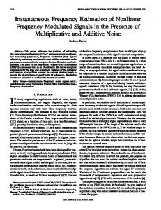
ZCPD cannot work normally under distorted grid condition. And the FFTPD has inherited error in phase detection. This error may lead the negative feedback system to a positive feedback one, thus limits the bandwidth of the system and even makes the system unstable [8]. In this paper, two three-phase DPLL methods based on DQPD with fixed or variable sampling frequency are discussed. According to the theoretical analysis and experimental results, the DPLL with fixed sampling frequency is suitable to be used in the condition of quick response fields, while the one with variable sampling frequency is proper to be adopted in some special fields, such as the application of high compensation precision APFs with repetitive control algorithm. Finally, experimental results verify the validity of theoretical analysis. II. THE MATHMATIC MODEL OF THREE-PHASE DPLL A. Basic Structure of Linear PLL A general PLL structure is illustrated in Fig.1 [1], which comprises a Phase Detector (PD), a Loop Filter (LF), and a Voltage Controlled Oscillator (VCO), each of them can be implemented in several different forms. If the signal to be tracked (reference) is an analog signal, the most suitable type of PD is a product-type. A product-type PD plus a linear LF have linear behavior to small variations of input signal, yielding a linear PLL [3]. B. The mathematic model of three-phase DPLL with fixed sampling frequency In three-phase system, for the reason that the dq transform contains the phase information of input variables, therefore, the PLL circuit can be implemented by using the dq transform and appropriate loop filter. The block diagram of this kind of three-phase PLL can be described in Fig. 2. The three phase utility voltages can be represented as follows,
Fig. 1. Block diagram of a general linear PLL.
712
ω ff
LF Reference
+
Δω
PI(s)
ω ff
VCO
ωˆ
-
θ (s)
θˆ
1 s
Δ( s)
Δω ( s )
ωˆ ( s )
1 s
θˆ ( s )
PD Δθ
tg
−1
(u
q
/ ud )
sin θˆ cos θˆ
Tdq0
Fig. 3. Linearized model of three-phase PLL.
u a ub u c utility voltage Fig. 2. Block diagram of three-phase PLL based on DQPD.
⎡ sin (ωi t + θ i ) ⎤ ⎢ ⎥ uabc = Vm ⋅ ⎢sin (ωi t + θi − 2π 3) ⎥ (1) ⎢⎣sin (ωi t + θ i + 2π 3) ⎥⎦ where uabc = [ua ub uc]T. Under the assumption of the balanced utility voltage, equation (1) can be rewritten in the synchronous rotating frame as ⎡ cos ωi t + θi − θˆ ⎤ ⎢ ⎥ (2) udq 0 = T θˆ ⋅ uabc = Vm ⋅ ⎢⎢ sin ωi t + θi − θˆ ⎥⎥ ⎢ ⎥ 0 ⎢⎣ ⎥⎦ T ˆ where udq0 = [ud uq u0] , and T θ denotes the synchronous rotating transformation matrix and given by ⎡ sin θˆ sin θˆ − 2π 3 sin θˆ + 2π 3 ⎤ ⎢ ⎥ 2 T θˆ = ⎢⎢ cos θˆ cos θˆ − 2π 3 cos θˆ + 2π 3 ⎥⎥ (3) 3 ⎢12 ⎥ 12 12 ⎢⎣ ⎥⎦ Then the error Δθ can be depicted as Δθ = ωi t + θ i − θˆ = tg −1 ( uq / ud ) (4)
( (
()
) )
()
()
( (
) )
( (
) )
The angular frequency of the PLL can be represented as dθˆ ωˆ = = PI (Δθ ) + ω ff (5) dt When reference signal is set to zero, the PLL frequency ωˆ and phase θˆ can track the utility frequency ωi and phase angle θ respectively by the proper design of the loop filter. And ωff is the feed forward frequency command introduced to improve the overall tracking performance of the PLL The linearized model of the three-phase PLL system can be described in Fig. 3. The error transfer function of the closed loop can be given as Δ (s) s (6) H (s) = = θ ( s ) PI ( s ) + s where θ ( s ) and Δ ( s ) denote the Laplace transform of θ and Δθ respectively. The proportional-integral (PI) controller served as the loop filter which can be given as
⎛ 1 ⎞ PI ( s ) = K P ⎜ 1 + (7) ⎟ ⎝ TI s ⎠ where KP and TI are the gain and time constant of the PI controller respectively. Equation (6) can be rewritten as s2 (8) H (s) = 2 s + 2ωnξ s + ωn 2
where ωn =
KP K 1 ,ξ= P = K PTI . TI 2ωn 2
Since the system is implemented in digital manner with DSP, the discrete-time model is more useful and accurate than the continuous-time one. Equation (7) and (8) can be discretized in z-zoom by using Back-Euler method as follows: K z (9) PI (z ) = K p + I z −1 2 Δ ( z ) a ( z − 1) (10) H (z) = = 2 θ ( z ) z − bz + a where K I = K p b=
Ts 1 ,a = , TI K pTs + K I Ts + 1
K pTs + 2 K pTs + K I Ts + 1
,and Ts is the sampling period.
Fig. 4 gives the block diagram of the DPLL system with fixed sampling frequency in the z-domain.
ω ff
θ (z)
Δ( z )
Δω ( z )
ωˆ ( z )
Ts z z −1
θˆ ( z )
Fig. 4. Z-domain model of three-phase DPLL with fixed sampling frequency.
C. The mathematic model of three-phase DPLL with variable sampling frequency The Numerical Control Oscillator (NCO) could be emulated by a digital counter of DSP [8] as depicted in Fig. 5. The NCO output signal’s period T can be expressed as T = N × Ts (11) where N represents the number of sampling points in a fundamental period and Ts indicates the sampling period determined by the DSP’s counter.
713
LF
θ (k )
Δθ
+
PI
ω ff Δω ( k )
-
+
+ωˆ k ( )
where z1,2 = e NCO Counter
θˆ(k )
Fig. 5. Discrete-time domain model of three-phase DPLL with variable sampling frequency.
The signal’s period T can be adjusted accordingly by changing the value of either Ts or N. In order to obtain the fixed sampling points per fundamental cycle, the sampling period Ts is adjustable. The phase angle of the NCO output signal at k beat in Fig. 5 can be depicted as θˆ ( k ) = k ⋅ Δφ (k=0, 1…N–1) (12) where Δφ = 2π/N. The Phase angle of utility voltage vector shown in Fig. 5 can be presented in discrete-time zoon as θ ( k ) = ωi ⋅ Ts ( k − 1) + θ ( k − 1) (13)
Similarly,
Δθ ( k + 1) = ωi ⋅ Ts ( k ) + θ ( k ) − θˆ ( k + 1)
III. EXPERIMENTAL RESULTS The two DPLL methods were implemented with fixedpoint arithmetic in TMS320F2812 DSP for a 380V/50Hz based three-phase APF. Fig. 6 and Fig. 7 show the start-up dynamic responses of the both DPLL strategies with different closed loop bandwidths respectively. The control loop parameters that calculated by using poles-placement method are given in Table I and TableⅡ respectively. TABLE I PARAMETERS FOR DPLL WITH FIXED SAMPLING FREQUENCY
Bandwidth(Hz)
5
50
500
ωn(rad/sec)
31.42
314.2
3412
ξ
0.707
0.707
0.707
KP
44.4279
444.2788
4442.8
KI
0.0705
7.0515
705.15
TABLE Ⅱ PARAMETERS FOR DPLL WITH VARIABLE SAMPLING FREQUENCY
(14) (15)
Bandwidth(Hz)
5
10
25
ωn(rad/sec)
31.42
62.84
157.08
ξ
0.707
0.707
0.707
KP
378.39
755.10
1888.3
KI
0.0016
0.0032
0.008
Using (11), (12), (14) and (15), the phase error transfer equation in discrete time domain can be developed as Δθ ( k + 1) − Δθ ( k ) = ωi ⋅ (Ts ( k ) − Ts ( k − 1) ) + θ ( k ) − θ ( k − 1) − 2π N = ωi ⋅ Ts ( k ) − 2π N
(16)
where Ts(k) = p·T1(k) = Ti/N – p·Tclock·PI[Δθ(k)]; T1(k) is the value of the DSP counter; p is determined by the working mode of the digital counter, e.g. p=1 if the counter works in continuous-up mode while p = 2 if it works in continuousup/-down mode in TMS320F2812 DSP; Tclock is the clock period of the counter. Equation (16) can be expressed as Δθ ( k + 1) − Δθ ( k ) = − p ⋅ ωi ⋅ Tclock ⋅ PI ⎡⎣ Δθ ( k ) ⎤⎦ (17)
and p1,2 = −ωnξ ± jωn 1 − ξ 2 ; ωn is the
nature frequency and ξ is the damping coefficient. The parameters of the PI controller can be calculated by (18) and (19).
Using (12) and (13), the phase difference between utility voltage vector and the synchronous signal of DPLL is Δθ ( k ) = θ ( k ) − θˆ ( k ) = ωi ⋅ Ts ( k − 1) + θ ( k − 1) − θˆ ( k )
p1,2Ts
From Fig. 6 and Fig. 7, it can be seen that higher closed loop bandwidth results in faster dynamic response. In addition, DPLL with variable sampling is unstable when the bandwidth is higher than 25 Hz due to the different mechanism of realization of NCO.
The phase error closed loop transfer function can be developed from the differential equation as D ( z ) = ⎡⎣ z − 1 + p ⋅ Tclock ⋅ PI ( z ) ⎤⎦ (18)
Observed from the above equation, the model of the DPLL circuit with variable sampling frequency is a first-order system. When PI controller is adopted as the loop filter, the closed loop transfer function becomes a second-order one. The poles of the system can be configured accordingly in sdomain. With the settled poles in z-domain, the expecting closed loop transfer function can be expressed as D ' ( z ) = ( z − z1 )( z − z2 ) (19)
(a)
714
Va
synchronized
10ms/div
t/ms
(b)
(b)
(c) Fig. 6. Dynamic resposens of three-phase DPLL with fixed sampling frequency at start-up ,(ξ= 0.707). (a) ωn = 31.42 rad/sec,. (b) ωn = 314.2 rad/sec,. (c) ωn = 3142 rad/sec.
(c) Fig. 7. Dynamic resposens of three-phase DPLL with variable sampling frequency at start-up (ξ= 0.707). (a) ωn = 31.42 rad/sec,. (b) ωn = 62.84 rad/sec, (c) ωn = 157.08 rad/sec.
The experimental results of the DPLL under the distorted voltage are shown in Fig. 8, where the 11th harmonic is 10% of the fundamental. It indicates that DPLL with either fixed or variable sampling frequency are immune to the harmonics because of the low pass characteristics of the controller.
(a)
(a) DPLL with fixed sampling frequency
715
Volt/V
Further more, the compensation performance of the APF without and with the repetitive control algorithm is compared in Fig. 10, where the iS, iC and iS is the load, compensation and grid currents respectively. It can be seen that repetitive control plays a significant role in APFs. When repetitive control is adopted, the DPLL with variable sampling frequency is required to achieve fixed sampling points per period for internal mode values refreshment.
Va
155V/div
Output of PLL
5ms/div
t/ms
(b) DPLL with variable sampling frequency Fig. 8. Experimental results under serious distortion condition (THD =10%).
Fig. 9 shows the DPLL operate under unbalanced condition, voltage magnitudes of phase A ,B and C are 100%, 80% and 115% respectively. Results show that both DPLL with fixed and variable sampling frequency can also track the input signal very well.
205V/div
Volt/V
(a) Experimental results of the APF without repetitive algorithm.
(b) Experimental results of the APF with repetitive algorithm. Fig. 10. The steady state compensation performance of the APF.
(a) DPLL with fixed sampling frequency
(b) DPLL with variable sampling frequency Fig. 9. Experimental results under unbalanced condition.
IV. CONCLUSION This paper addresses the two type DPLL methods for active power filters. Conclusions can be made through theoretical analysis and experimental results above as: (a) Both the DPLL based on the dq-transform phase detection with fixed and variable sampling frequency can track the input signal well under distorted and/or unbalanced utility condition. (b) DPLL with variable sampling frequency has a limited bandwidth e.g. 25 Hz in this paper, which means slower dynamic response compared with the one based on fixed sampling frequency. (c) In some particular applications, e.g. a repetitive controlled APF, where dynamic response is less important than steady-state compensation precision, the DPLL with variable sampling frequency is required. In addition, the two DPLL strategies discussed in this paper can be easily adapted to single-phase system.
716
ACKNOWLEDGMENT The authors would like to thank the sponsorship of NCET Program of Ministry of Education, China (#060512) [1] [2] [3] [4]
REFERENCES V. Kaura, and V. Blasko, “Operation of a phase locked loop system under distorted utility conditions,” IEEE transaction on Industry Applications, vol. 33, no. 1, pp. 58-63, 1997. Arruda, L. N., Silva, S. M. and Filho, B. J. C., “PLL structures for utility connected systems”, in Proceedings of the 2001 Industry Applications Society Conference, pp. 2655-2660. Se-Kyo Chung, “A phase tracking system for three phase utility interface inverters”, IEEE Transactions on Industrial Electronics, vol.15, no.3, 431-438, May 2000. L.G. Barbosa Rolim, D.R. da Costa, and M. Aredes, “Analysis and software implementation of a robust synchronizing PLL circuit based on the pq theory”, IEEE Transactions on Industrial Electronics, vol.53, no.6, 1919-1926, December 2006.
[5] D. Yazdani, A. Bakhshai, G. Joos, and M. Mojiri, “A single-phase adaptive synchronization tool for grid-connected converters”, IEEE IECON 2008, pp. 526-529, 10-13 Nov. 2008. [6] Hamasaki, S. Fujii, K. Tsuji, M. Chen, S. “A novel method of active filter control using repetitive control,” Electrical Machines and Systems, 2005. ICEMS 2005. Proceedings of the Eighth International Conference on. Volume 2, Page(s):1252 – 1256, Sept. 2005. [7] Garcia-Cerrada, A. Pinzon-Ardila, O. Feliu-Batlle, V. Roncero-Sanchez, P. Garcia-Gonzalez, P. “Application of a Repetitive Controller for a Three-Phase Active Power Filter,” IEEE Transaction on Power Electronics, Vol. 22, No. 1, pp. 237–246, 2007. [8] Kong xuejuan, “The key techniques research on the digital controlled PWM Inverter”, Wuhan China: Huazhong University of Science and Technology Library. 2005 [9] da Silva, C., R. Pereira, et al. "A Digital PLL Scheme for Three-Phase System Using Modified Synchronous Reference Frame."IEEE Transactions on Industrial Electronics, PP(99): 1-1. 2010
717