Computer Aided Process Planning (CAPP): The User. Interface for ...... Tool (APT)
code to run a Computer Numerical Control (CNC) machine. The FP module of ...
CUMENTATION PAGE
AD-A250 095
. .'.-,
C.
es
ip,:. CS
.' .
. j
~~ ~ ~
t,
an .'.Aoer
,n
".s....
a~. U0Q-
2. REPORT DATE
v
3
uomC
t"P
or 01
~.
FtVCeto
r
.. v
P, 'e
CePn- flns.' rI ?n
1c(0
G4-0 B1 O
Se."
-~ er sC
' "
o'
.S r~~
REPORT TYPE AND DATES COVERED
191
4. TITLE AND SUBTITLE
,r, Ap.,ov' o"k
.
FUNDING NUMBER
Computer Aided Process Planning (CAPP): The User Interface for The Fabrication Module of the Raloid -asign System 6. AUTHOR(S)
Cartaya, Christine M., Captain 8. PERFORMING ORGANIZATION REPORT NUMBER
7. PERFORMING ORGANIZATION NAME(S) AND Az-RESS(ES)
AFIT Student Attending:
University 6f Dayton
AFIT/CI/CIA-91-129
1OTICl 9. SPONSORING/MONITORING
A
AGENCY NAME(S) AND ADDRS")
ELECTE
AFIT/CI Wright-Patterson AFB OH 45433-6583
11. SUPPLEMENTARY
MAY
7 1992
10. SPONSORING YMONITORING GENCY REPORT NUMBER
NOTES
12a. DISTRIBUTION /AVAILABILITY
12b. DISTRIBUTION CODE
STATEMENT
Approved for Public Release lAW 190-1 Distributed Unlimited ERNEST A. HAYGOOD, Captain, USAF Executive Officer 13. ABSTRACT (Maximumn 200 words)
15. NUMBER OF PAGES
14. SUBJECT TERMS
112 16. PRICE CODE 17.
SECURITY CLASSIFICATION OF REPORT
NSN 7540-01-280-5500
18.
SECURITY CLASSIFICATION OF THIS PAGE
1 9.
SECURITY CLASSIFICATION OF ABSTRACT
20. LIMITATION OF ABSTRACT
Stanoard Forr- 298
e,
2-8g?
DISCLAIMEI NOTICE
THIS
DOCUMENT
IS
BEST
QUALITY AVAILABLE. THE COPY
FURNISHED TO DTIC CONTAINED A SIGNIFICANT
NUMBER
PAGES WHICH DO REPRODUCE LEGIBLY.
OF NOT
,,,f jl
--
~
oo
COMPUTER AIDED PROCESS PLANNING (CAPP): THE USER INTERFACE Name:
Cartaya, Christine Marie
A,....
University of Dayton, 1991 Advisor:
fi pecl.al,
Dr. John P. Eimermachert3"
-
The Rapid Design System (RDS) is a feature based design, fabrication, and inspection system.
Research and development of the The
RDS has been sponsored by the United States Air Force.
Fabrication Planning (FP) Module of the RDS is being developed by the University of Dayton.
The FP module automatically creates a
process plan for machining a metal part.
The research addressed
herein deals with the User Interface for the review and modification of a process plan. The Fabrication Planning Module automatically creates a plan using information from the Feature Based Design Environment (FBDE) of the RDS.
It integrates this information with the information
received from a program/database called MetCAPP plan is created in a series of steps:
TM .
The process
feature translation, feature
sequencing, setup generation, and operations generation.
The
purpose of the Planning Window and User Interface is to give a designer, machinists, or process planner the ability to automatically generate and manipulate a complete process plan.
92
5 01" 009
and/or
092-11971 llll
By using the user Interface, the final process plan can be modified in many different ways.
The translation of a design
feature to a more appropriate MetCAPPTM manufacturing feature can be accomplished.
Manufacturing features can be moved between
setups, setups can be added or deleted, and machining operations generated by MetCAPPTM can be changed. Finally, when an acceptable plan has been generated, the code to run a Computer Numerically Controlled (CNC) machine is generated. The research here addresses the process of generating and changing a process plan. Work was done in the area of feature translation, the effect of changing a setup, and the effect of changing the machining operations.
At each step in the process, the
designer, process planner, or machinist is given the opportunity to accept what has been generated or change it. By allowing changes, the results of both future and prior steps may be affected.
Code was
written that tracks these affects and regenerates the necessary parts of the plan. This thesis documents the parts of the plan that may be changed, the affects of making such changes, and the code to implement the research results.
ABSTRACT
COMPUTER AIDED PROCESS PLANNING (CAPP): THE USER INTERFACE FOR THE FABRICATION MODULE OF THE RAPID DESIGN SYSTEM Name:
Cartaya, Christine Marie
University of Dayton, 1991 Advisor:
Dr. John P. Eimermacher
The Rapid Design System (RDS) is a feature based design, fabrication, and inspection system.
Research and development of the
RDS has been sponsored by the United States Air Force.
The
Fabrication Planning (FP) Module of the RDS is being developed by the University of Dayton.
The FP module automatically creates a
process plan for machining a metal part.
The research addressed
herein deals with the User Interface for the review and modification of a process plan. The Fabrication Planning Module automatically creates a plan using information from the Feature Based Design Enviro-iment (FBDE) of the RDS.
It integrates this information with the information
received from a program/database called MetCAPPTM. plan is created in a series of steps:
The process
feature translation, feature
sequencing, setup generation, and operations generation.
The
purpose of the Planning Window and User Interface is to give a designer, machinists, or process planner the ability to automatically generate and manipulate a complete process plan.
By using the user Interface, the final process plan can be modified in many different ways.
The translation of a design
feature to a more appropriate MetCAPPTM manufacturing feature can be accomplished.
Manufacturing features can be moved between
setups, setups can be added or deleted, and machining operations generated by MetCAPPTM can be changed. Finally, when an acceptable plan has been generated, the code to run a Computer Numerically Controlled (CNC) machine is generated. The research here addresses the process of generating and changing a process plan.
Work was done in the area of feature
translation, the effect of changing a setup, and the effect of changing the machining operations.
At each step in the process, the
designer, process planner, or machinist is given the opportunity to accept what has been generated or change it. By allowing changes, the results of both future and prior steps may be affected.
Code was
written that tracks these affects and regenerates the necessary parts of the plan. This thesis documents the parts of the plan that may be changed, the affects of making such changes, and the code to implement the research results.
COMPUTER AIDED PROCESS PLANNING (CAPP) THE USER INTERFACE FOR THE FABRICATION PLANNING MODULE OF THE RAPID DESIGN SYSTEM
Thesis Submitted to Graduate Engineering & Research School of Engineering UNIVERSITY OF DAYTON In Partial Fulfillment of the Requirements for The Degree Master of Science in Mechanical Engineering
by Christine Marie Cartaya UNIVERSITY OF DAYTON Dayton, Ohio December 1991
©Copyright by Christine M. Cartaya All rights reserved 1991
COMPUTER AIDED PROCESS PLANNING (CAPP): THE USER INTERFACE FOR THE FABRICATION PLANNING MODULE OF THE RAPID DESIGN SYSTEM
APPROVED BY:
John Eimermacher, Ph.D. Advisory Committee, Chairman Professor, Mechanical and Aerospace Engineering Department
Franklin E. Eastep, Ph.D. Interim Associate Dean/Director Graduate Engineering & Research School of Engineering
Patrick J. Sweeney, Ph.D. Interim Dean School of Engineering
ii
ABSTRACT
COMPUTER AIDED PROCESS PLANNING (CAPP): THE USER INTERFACE FOR THE FABRICATION MODULE OF THE RAPID DESIGN SYSTEM Name: Cartaya, Christine Marie University of Dayton, 1991 Advisor:
Dr. John P. Eimermacher
The Rapid Design System (RDS) is a feature based design, fabrication, and inspection system.
Research and development of the
RDS has been sponsored by the United States Air Force.
The
Fabrication Planning (FP) Module of the RDS is being developed by the University of Dayton.
The FP module automatically creates a
process plan for machining a metal part.
The research addressed
herein deals with the User Interface for the review and modification of a process plan. The Fabrication Planning Module automatically creates a plan using information from the Feature Based Design Environment (FBDE) of the RDS.
It integrates this information with the information
received from a program/database called MetCAPPTM. plan is created in a series of steps:
The process
feature translation, feature
sequencing, setup generation, and operations generation.
The
purpose of the Planning Window and User Interface is to give a
iii
iv designer, machinists, or process planner the ability to automatically generate and manipulate a complete process plan. By using the user Interface, the final process plan can be modified in many different ways.
The translation of a design
feature to a more appropriate MetCAPPTM manufacturing feature can be accomplished.
Manufacturing features can be moved between
setups, setups can be added or deleted, and machining operations generated by MetCAPPTM can be changed. Finally, when an acceptable plan has been generated, the code to run a Computer Numerically Controlled (CNC) machine is generated. The research here addresses the process of generating and changing a process plan.
Work was done in the area of feature
translation, the effect of changing a setup, and the effect of changing the machining operations.
At each step in the process, the
designer, process planner, or machinist is given the opportunity to accept what has been generated or change it. By allowing changes, the results of both future and prior steps may be affected.
Code was
written that tracks these affects and regenerates the necessary parts of the plan. This thesis documents the parts of the plan that may be changed, the affects of making such changes, and the code to implement the research results.
ACKNOWLEDGEMENTS I would like to express my appreciation to the people at the Manufacturing Research section of the Materials Laboratory at Wright Patterson Air Force Base for their support of this project. Especially to Charles Wright for patiently teaching me LISP. Most importantly, I would like to thank my husband, Ulises, for all his love and support throughout the this research.
v
VITA
November 14, 1964
Born - Miami, Florida
1986
B.S., University of Miami, Coral Gables, Florida
1986 - 1990
Contracting Officer, Ogden Air Logistics Center, Hill Air Force Base, Utah
1991
M.S., University of Dayton, Dayton, Ohio
FIELDS OF STUDY Major Field:
Integrated Manufacturing, University of Dayton
vi
TABLE OF CONTENTS
ABSTRACT................................................................................I ACKNOWLEDGEMENTS...................................................................
v
VITA..
Vi
..................................................................................
TABLE OF CONTENTS ..........................................................
........ viI
LIST OF FIGURES .........................................................................
x
LIST OF TABLES ..........................................................................
x .1
CHAPTER 1.
INTRODUCTION ...........................................................
1
The Rapid Design System............................................ 6 Statement of the Problem .......................................... 9 11.
111.
PLANNING WINDOW.....................................................
12
The Manufacturing Window ......................................... Setup Window.............................................................
13 15
THE USER INTERFACE ..................................................
17
Feature Translation.....................................................1 7 Developing Algorithms for Modifying the Process Plan .......................................................................... 23 IV.
USING THE USER INTERFACE ........................................
29
The Layouts, Forms, and Icons...................................... 29 Modifying the Process Plan .......................................... 31 V.
TRACKING THE PLANS AND USERS................................ 48
vi i
vII
Tracking the Plan ...................................................... 48 Tracking the Users ............................................. ........ 49 VI.
CONCLUSION ..............................................................
50
VII.
RECOMMENDATIONS ....................................................
52
APPENDIX A................................................................................
55
APPENDIX B................................................................................
60
Object Definitions ............................................................. Fabrication
Planner ...............................................
Plan ......................................................................
60 6 0 6()
Setup..................................................................._6 The Manufacturing Top Level Window................................... 62 Plan
Manufacturing...............................................6
Manufacturing Layout.............................................6
3
Manufacturing Plan Form.......................................6
3
Modifying
the
Feature Translation
"Des ign-to-Man ufac tu ri iq 5
(Modify D32).........................6
Header Information.................................................7
8
Modify Setup ........................................................
79
Completed Plan ......................................................
7 9
Done .....................................................................
80
Modifying the Setups.......................................................... 81
ix Setups Modification
Layout ....................................
8 1
Form for Setups Modification Layout...................... 8 1 Deleting a Setups...................................................8
3
Adding a Setup......................................................8
3
Adding a Feature................................................... Deleting, A Feature.................................................8
83 4
View Fixturing..-11-..............................................
84
Quantity/Machine .................................................
84
View Operations .....................................................
85
Reorder Operations........................................... Delete an Operation .......................................... Change Tool ..................................................... Change Speed ................................................... Change Feed .....................................................
89 89 90 90 91
Tooling..................................................................9
1
Done (Setups)........................................................
108
Printing the Plan, Tool Data, and Evaluation Form................. 108 Printing the Plan.................................................... 10 8 Printing the Evaluation Form ..................................
109
Miscellaneous Functions ............................................ ....... 111 BIBLIOGRAPHY...........................................................................
11 3
LIST OF FIGURES
1.
Overall View of the RDS ......................................................................
7
2.
Fabrication Planning Flow ...................................................................
11
3.
Manufacturing Planning Top Level Window ..................................
14
4.
Setups Modification W indow .............................................................
16
5.
Revised Fabrication Planning Flow ................................................
18
6.
Manufacturing Features .......................................................................
19
7.
S e tu p s F lo w .............................................................................................
8.
Modifying the Operations ...................................................................
27
9.
Sample Code for a Layout ....................................................................
29
10.
Header Information Screen .................................................................
33
1 1.
M od ify D2 S cree n ..................................................................................
12.
Sample Code for Viewing the Current Setup ...............................
36
13.
Manufacturing Operations by Setup .................................................
39
14.
Sample Code for Non Insertable Milling Cutter ........................
42
15.
Tooling Information Screen ...............................................................
43
16.
Complete Process Plan .......................................................................
45
17.
Printed Process Plan ............................................................................
46
x
. .24
. . 34
LIST OF TABLES
1.
MetCAPPTM Results for Pocket .........................................................
21
2.
MetCAPPTM Results for Open Step .................................................
55
3.
MetCAPPTM Results for Step to a Shoulder .................................
55
4.
MetCAPPTM Results for Through Slot ............................................
56
5.
MetCAPPTM Results for Open Pocket .............................................
56
6.
MetCAPPTM Results for Cutter Axis Parallel ..............................
57
7.
MetCAPPTM Results for Cutter Axis Perpendicular ................. 57
8.
MetCAPPTM Results for Biased Pocket ..........................................
9.
MetCAPPTM Results for Hole with Diameter Greater Than 2 Inc he s ..................................................................................................... . . 59
xi
58
CHAPTER
I
INTRODUCTION
In traditional manufacturing planning, a machinist or process planner first examines the part specifications or drawings of the part.
The planner then develops a plan based on past experience with
similar parts and his knowledge of the resources available.
Physical
differences between parts must be considered, e.g. a similar but slightly larger or smaller part may not fit on the same machine.
The
capacity of each piece of equipment and the timing of material to the equipment must be taken into consideration.
Also, the
capabilities of new machines and equipment must be taken into consideration to avoid duplication of effort between machines.
Any
two process planners, even with similar background, may develop different process plans.
This means that even standard plans could
be inconsistent and inefficient.
To combat this, companies attempt
to standardize. Computer Aided Process Planning (CAPP) is the use of specialized computer systems to aid in process planning. comes in two forms, variant and generative.
CAPP
Variant systems utilize
previously developed process plans which are stored in the computer.
Variant systems not only store completed process plans
but also the elements which go into their development.
Elements
such as machine capacities and material specifications, as well as
2 design attributes are coded and stored in the system.
Some codes
are developed based on the attributes stored, although various types of coding systems are used.
The codes used in variant systems
classify parts into part families. is created for that part.
As new parts are generated a code
The system then looks for a previously
stored process plan with a similar code.
The plan presented can then
be used as is or modified. The new plan can then be stored under a new code. Generative systems, on the other hand, have no previous plans stored.
They create a process plan every time a part number is
entered into the system.
These systems are based mostly on logic
rules, design characteristics, formulas, and algorithms.
All
elements of the manufacturing process (machine types available, machine specification, capacity, material specification, etc.) are programmed into the computer. elements.
As
Parts are coded based on the above
a process plan is needed, the computer searches all
the possible combinations based on the code entered and develops a plan. There are two major components to most generative systems. The first is a geometry based coding scheme to translate part specifications and drawings into computer understandable data. This scheme must be done with great detail in order for the computer to manipulate the data.
The coding scheme must also
include data on the tools and machines used.
This is necessary to
insure that parts are put through these machines correctly and in the most efficient manner.
The second component is the software.
It
3 must compare geometry and specification with the manufacturing capabilities to develop the process plan.
Frequently the software
includes the ability to print out the plans and provide the codes needed for CNC machines. Some of the advantages of using computers are reduced labor cost of preparing a process plan, reduced training costs of new planners, and mitigation of the impact of employee turnover.
Plan
consistency will also improve and CAPP can be a useful tool in improving manufacturing operations.
Variant systems, while
simpler to create and easier to introduce to a facility, have limitations.
As new machines or manufacturing processes are
added, the computer database must be manually updated.
An expert
process planner is also needed to help create and maintain the system.
It sometimes requires the referencing of external manuals
or charts to modify an existing plan for use. The advantage of generative process planning is the quick response to change.
Since a new plan is generated every time, any
change to the manufacturing process plan can be included quickly. With equipment capabilities known to the computer, duplication is reduced.
It is also fully automatic which means less human
intervention with less chance of error. Artificial Intelligence (AI)
programs or expert systems are
sometimes used to develop generative CAPP software.
Al programs
analyze part geometries based on symbolic representations.
They
produce a logical sequence of operations to manufacture a part.
4
taking into account appropriate machine parameters.
An alteration
of the knowledge base (not the core program) provides an easy way to keep up with changes.
They provide the "brains" to a generative
system. Two basic approaches for using Al in process planning are interactive and batch mode.
An expert system that works in batch
mode processes several jobs submitted in a batch.
These systems
require or allow little interaction with the process planner. process planning systems today run in batch mode.
Most
The advantage of
batch mode is that it requires less time to run than to interact with the system.
The user interface for a batch system only consists of a
means to start the planning, display results, and if possible provide an explanation 2 . The disadvantage of batch mode is that the process planner has no capability to modify the plan except by hand.
In order
for the system to gain knowledge and improve its ability to create plans, changes have to be made in the base line program. In an interactive system the process planner consults the system for advice (similar to advice from a human expert).
The
advantage is that through this interaction both the system and the process planner can learn to make better plans.
The user interface
would consist of several menus or forms with a series of questions or inputs for the process plan to provide.
The major disadvantage is
that it leads to long planning sessions. 2 However, no system is capable of providing a "perfect" or "optimal" process plan.
Part of the problem is that what is optimal
5 today may not be optimal tomorrow.
The process planner needs the
capability to either change the parameters of manufacturing knowledge in the system before the process plan is developed or change the process plan itself. This need has been recognized since the first CAPP systems were developed.
The variant system
developed by Computer Aided Manufacturing International-Inc. (CAM-I) was an interactive system which required no specialized training by the operator. A generative feature based design system known as Quick Turnaround Cell (QTC) ran in batch mode 2 . The user interface consisted of a design window to create the features and a process planning window.
Once activated, the process planning system
automatically generates a process plan without input from the user. When complete, process planning documentation is displayed and the CNC code is generated.
This system generates process plans
relatively quickly but has one major disadvantage.
Without user
input, any changes to the knowledge in the process planning system has to be changed in the baseline code. The RDS avoids this problem.
It provides both the capability to
allow user input to the plan and the ability to automatically generate a process plan through the EAM and the User Interface. Since the EAM can learn from previous design, this flexibility gives the RDS the advantage of being able to improve process planning capability.
6 The Rapid Design System The Rapid Design System (RDS) is a United States Air Force inhouse research project within the Wright Laboratory at WrightPatterson Air Force Base, Ohio.
The research objective is
development of a next generation Computer Aided Design/Manufacturing/Inspection System for machined piece parts. 4 The RDS utilizes a memory driven, feature based design system integrated with an intelligent fabrication and inspection system process planning system.
This integration allows the RDS to
automatically evaluate a design and generate the fabrication and inspection plans. The RDS consists of an Episodal Associative Memory (EAM) module, a Feature Based Design Environment (FBDE) module, a Fabrication Planner (FP) module, and an Inspection Planning and Evaluation (IPEM) module. The EAM uses neural net technology to cluster designs. with
Along
the ability to store and retrieve designs based on geometric
similarity, it has the ability to "learn".
As new designs are added,
the memory reclusters the designs using the information gathered from the new designs.
With these designs clustered in the memory,
the EAM can then "learn" what type of designs are good and what are not.
It can then prompt the designer, through development of new
constraints, when a part has been designed incorrectly.
7
Feature Based
Fabrication
Desi gn Environment
Planner
(FBDE)
(FP)
inspection Planning & Evaluation Module (IPEM)
Episodal Associative Memory (EAM)
Design
Manufacturing Plan
Inspection Plan
Manufacturing Features
Inspection Features
Product & Process Specificaction Figure
1. Overall View of the
RDS
Traditional Computer Aided Design systems use lines and arcs to describe a part.
The RDS through the FBDE uses features.
Features such as holes, pockets, and edge cuts, allow the designer to specify relationships among features.
These relationships include
not only distances between features but also the fact that one feature may be attached to another, such as a hole in the bottom of a pocket.
Features allow the FBDE to capture more information about
the part than just the dimensions.
Information concerning the
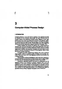
process, i.e. need to manufacture and inspect the part, are also included. The FP module produces a manufacturing process plan for machining prismatic parts. from the FBDE.
A plan is created using the information
The plan is created in a series of steps.
Each of
8 these steps, feature translation, feature sequencing, setup generation, and operations generation, can be generated automatically and can be modified.
When an acceptable plan has
been completed, the FP generates the Automatically Programmed Tool (APT) code to run a Computer Numerical Control (CNC) machine. The FP module of the RDS system uses a combination of generative and variant process planning.
The RDS uses variant
process planning in that it can store and retrieve previous parts and their process plans.
Parts are stored in a database and can be
retrieved by part name or by similar design. mostly generative process planning.
However, the RDS uses
It has the ability to generate a
complete process plan from a FBDE design without any input from the process planner.
All elements of the manufacturing process (i.e.
available machine types, machine specification, material specifications, feature sequencing, and feature interactions) are programmed into the system.
As a process plan is needed, the
system uses the design data from the FBDE and machining knowledge and develops a plan. The integration of the FBDE and FP modules allows the designer to check for producibility of a design in the preliminary phases.
This can mean less rework and fewer
engineering change orders.
This also means that rapid prototyping
can be accomplished cheaply. The RDS receives its machining information from a system/database called MetCAPPTM.
MetCAPPTM is a stand alone
CAPP program which generates machining information for a single feature.
MetCAPPTM algorithms are based on feature dimensions,
9 machine selection, and material and designed to be used interactively to create a feature by feature process plan for a part. MetCAPPTM makes no consideration for feature sequencing, feature interactions, or the design of the part as a whole.
This means that
optimization is accomplished done by the designer, planner, or machinist.
The RDS uses MetCAPPTM to obtain the machining
operations for each feature.
These operations include the tool data,
spindle speed and feed, and the estimated time to machine the part. Once these operations are obtained, the RDS manipulates the information to create a complete machining process plan. Statement of the Problem The initial planning window and user interface for the RDS had two
major limitations.
The first limitation was that they
consisted of only three functions.
The first function was the ability
to translate design features into manufacturing features with no input from the user.
The second function was to group the features
into setups based on approach faces only, again, with no input from the user.
The third function was to get the machining operations for
each feature by calling MetCAPPTM.
The current user interface and
planning window allows the user to interact with the system at each point of the planning process.
It also will adjust the outcome to
suit current needs. The second limitation was that planning was very inflexible. The RDS will simply back up to the beginning of the plan after doing a change.
If data is changed near the end of the planning process
10
that effects another part of the process above it, the whole plan had to be regenerated (reference Figure 2).
It is interesting to note that
in recalculating the plan, the change could be erased. In order to create a workable user interface, two conditions had to be met. was
First, a planning process had to be developed that
smart enough to allow changes at any step in the process
without having to regenerate the plan.
Second, this planning process
had to automatically regenerate any needed parts of the plan without destroying any changes previously made.
These changes could then
be stored as part of the design. Work on the User Interface was divided into two areas. first was the planning window.
The
This is the visual representation of
the manufacturing and design information needed to create a process plan.
The second is the user interface itself.
the functionality behind the planning window.
The user interface is It consists of the
algorithms and code used to produce the process plan.
11
DATA
Fabrication Operation Translate/
-(
Design Features (DI)
Refine Manufacturing
11
Features (D2) Determine setups and the D2 features in each setup. D2 Features are unordered.
Fixture Vz
Dependencies between features are identified.
Feature Sequence
Call MetCAPIP for each 1D2 feature. Get operations for each feature. For each operation get machining parameters. (tool, feed, speed, cutting time)
MetCAPP
Optimize
Order
Tools
Operations
Order operations to minimize tool change.
NC Code P
Figure 2. Fabrication
Planning Flow
CHAPTER
II
PLANNING WINDOW
In developing the planning window, data was collected on the type of information the user needed to interact and develop a complete machining process plan. several items.
This information consists of
First, information is needed about the part itself.
This type of information includes dimensions, part number, material, number and design-with features, and feature sequencing.
Second,
information is needed about the way in which the part will be manufactured.
This information consists of setup fixturing, setup
sequencing, and the features to be cut in each setup.
Using these
two types of information, the machines and processes available to manufacture the part can be determined.
This information includes
machine availability, operator availability, tool availability, and machining operation details.
Machining operation details are
operation descriptions (rough cut, drill, etc.), spindle speed, spindle feed, tool identification, operation order, cutting time, and APT/NC code generation. Once the data is collected, it is grouped by functionality.
The
main groups of functionality are part identification information (Part Number, Revision No., etc.), feature translation (design to manufacturing),
setup data (machine, quantity, etc.), fixturing,
machining operations, tool data, and APT/NC code.
12
Once the data is
13
grouped, windows, panes, and icons were developed to display the information. Appendix B.
The code for these windows, panes and icons are in Development of the functions and methods for actually
creating and editing the plan is part of the user interface.
This was
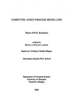
developed in conjunction with the planning window. The Manufacturing Window The planning window is actually two separate windows. first window is the manufacturing window (Figure 3). window a user, e.g. process planner, has several choices.
The
In this The user
can input the part identification information or generate a completed process plan without any input. The data needed here is received from the FBDE of the RDS and from MetCAPPTM. includes the identification information,
This data
the "design-to-
manufacturing" feature translation, setup information, and the fixturing information.
Machining operations and tool data are
received from MetCAPPTM.
The user can also generate APT/NC code,
modify the "design-to-manufacturing"
feature translation, switch to
the setups window (discussed below), or store the complete design and manufacturing plan. As an aid to the user, the ability to draw the wire frame representation, draw the solid representation, and change the graphical view of the design are included. The manufacturing window also includes an area which gives the user a means to view and edit various aspects of the manufacturing features or the machining plan
14
ri- dir hImfo [.4oy
I
02
-IP-O
PART- MODEL(?) K? DZ-STARTING-OLOCK(? DZ- RH-i (?) APPROACH- FACE- I-TRANSLATED
APPR OACH-FACE- I -TRANS3LATED0 OPEN-FACE-i DZ-TS-I C?) OPEtJ-FACE-3 OPEN-FACE-Z APPR OACH-FACE- I -T7RAN SLATE D OPEN-FACE-I TS-i(?) STANDOFF(?) PKT-i (7) OH-i(?) STANDOFFM? STANDOFF-PART
1x
Figure 3. Manufacturing Planning Top Level Window
15 itself. The ability to generate a completed process plan without guidance from an expert is important.
It allows the designer or
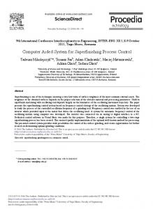
process planner to check for the manufacturability of the design. If there are problems in the design which prevent the part from being manufactured, the completed plan will show these problems. Setup Window The second window is the setup window (Figure 4). actually a subpart of the manufacturing window.
It is
This window is
accessed by clicking on the modify setup icon in the manufacturing window.
In this window, the user has nine options.
He can add
features to a setup, delete features from a setup, add a new setup, delete a setup, generate the manufacturing operations from MetCAPPTM, move back to the manufacturing window, view a list of the current setups and the features in each setup, view the surface areas available for the different types of fixturing, or change the part quantity or machine for a specified setup.
These abilities allow
the user to modify the setups and the individual machining operations to create an optimal process plan.
16
s R~~ 1-- 5Mata.
et _Fat
le
ew
IH AM-SPACE(?) JiPART-MODEL(?) DZ- STAR IING-OLOCK(7) APPROACH -FACE-i -TRANSLATED OPEN-rACE-I DZ-PKT-I (?) APPROACH-FACE- I -TRANSLATED OPIEN-FACE-1 DZ-TS-1 (?) OPEN-FACE-:i OPEN-FACE-Z APPROACH-rFACE-i -TRANSLATED OPEN-FACE-i TS-i(?) STANDOFF(?) PKT-I (7) eN-ic?) STANDOFF(?) STANDOFF-PART BOUNDARY-PART SOLID-PART INS PECiION- PLANNER(?) PATH-PLANNER INTERSECTION- PLANE PROPOSED-PATH CROSS- SECTION CONS TRAINT- MANAGER(?) PART-i (?) FABRICATION -PLANNER(?) PLAN(?) SETUP-Z(?) SIDE- O.AJ.PING(?) TOP-CAN4PING(?) VICE- FIXTURING(?) ALT-Z(?) PARA- FACE BASE -FACE AI.T-I(?) PARIA-FACE BASE-FACEZ SETUP-i (?)
'1
Figure 4. Setups Modification
Window
CHAPTER
III
THE USER INTERFACE
In developing the user interface, a new flow chart was developed (Figure 5) to highlight that each step of a process plan can be changed and dependant steps are recalculated in any order. The only limitations are the translation of design features into manufacturing features and the generation of APT/NC code.
Since
feature translation is the basis of the manufacturing planning, it will effect all other steps in the process. must always be done first.
Therefore, translation
Any changes to the feature translation
will cause the rest of the plan to be regenerated. is the final process to be completed. previous planning steps.
The APT/NC code
It depends on all of the
Any change to the previous steps creates a
situation where new APT/NC code must be generated. Feature Translation In order to create a complete manufacturing process plan, one must first translate the design features into manufacturing features.
Design features are used to represent the part graphically.
A manufacturing feature contains manufacturing information about a part.
The manufacturing information includes part dimensions as
well as the machining operations needed to manufacture the part. These manufacturing features are the basis for the rest of the machining planning. 17
18
Fabrication Operation
DATA DI Features
Translate/ Refine
D2 Features
IK Setups/ Fixture
I
Feature Sequence
Dependencies between features are identified.
Call MetCAPP for each 1)2 feature. Get operations for each feature. For each operation get machining parameters. (tool, feed, speed, cutting time)
MetCAPP
Optimize Too ls
10
Determine setups and the D2 features in each setup. D2 Features are unordered.
Order Operations
Nodil' oprtost lerations to Modify~m minimize tool change.
NC Code
PLAN
Figure 5. Revised
Fabrication
Planning
Flow
19
The RDS has separate design and manufacturing features.
The
manufacturing features in the RDS are the same features used by MetCAPPTM (Figure 6).
Cylinder
Block
Through Slot
S ~ Shoulder
Single Diameter Hole (Blind and Through)
Enclosed Pocket
Step tp
Flat Rect Surface: Cutter Axis Parallel. Cutter Axis Perpendicular
Ider
Open Pocket
Chamfer aEdge Form Milled Tapered
Tapped Hole; Through. Blind
Figure 6. Manufacturing
Counterbore
Features
MetCAPPTM is used to obtain machining information for a specific -eature.
This information includes the machining operation,
the tool, the spindle speed and feed, the number of passes the tool will make for each operation, and the time required to cut each
20
operation.
This feature translation is done automatically when
entering the manufacturing top level window.
However, some of the
design features do not have a one to one correlation with the MetCAPPTM features. Specifically, there are six untranslated features.
These are a hole (either blind or through) with a diameter
greater than 2 inches, a triangular pocket, a right triangular pocket, a biased pocket, and a quadrilateral.
To use these features,
must be translated as a current MetCAPPTM feature.
they
However, each
of these features may be machined. Each of these features will need to be milled.
In order to
determine which type of MetCAPPTM features is appropriate for each design feature, a number of tests were run.
First, a pocket with the
following dimensions was chosen. Length: 4" Width: 4" Depth: 4" Corner Radius: 0.1" Fillet Radius: 0.0313" Angle between floor and wall: 900 Maximum allowable cutter diameter: 2" Then, MetCAppTM was run using these dimensions for a pocket, an open step, a step to a shoulder, a through slot, an open pocket, a flat rectangular surface cutter axis parallel, and a flat rectangular surface cutter axis perpendicular.
The operations returned for these
features are similar but not identical. Tables 2 - 7 Appendix A.
The results are in Table 1 and
21 Table
1.
Tool
Operation Center
DLS-
Drill
001
Drill
Non Insert
Plunge End Mill Slot-endmill Rough-
MLS0288 MLS0288 MLS-
end-mill-
0272
MetCAPPTM
Results for Pocket
Cut
Total
Speed
Feed
Esi
aIsse
Depth
Depth
RPM*
IPM**
Time
1
0.097
0.097
5348
37.433
0.003
1
3.9419
3.9419
6909
35.927
0.190
1
4.0
4.0
891
3.742
0.988
2
1.2733
3.82
290
7.98
0.408
4
1.91
3.82
1141.0
16.77
0392
2
1.985
3.97
1454.0
28.79
0.431)
5
0.03
0.03
1273.0
26.73
0.275
1
4.0
4.0
19100
30.94
0.293
No
Drill
floor-wall
Semi-fin-
MLS-
cnd-mill-
0265
Fin-end-
MLS-
mill-floor
0217
Fin-end-
Milling Cutter
mill-wall *
IPM
=
Inches per minute
**
RPM = Revolutions per minute
These particular MetCAPPTM features were chosen for trial runs for specific reasons.
The first five features were chosen
because they are all types of pockets. of the features.
The difference is the location
The other two features, a flat rectangular surface
cutter axis parallel and a flat rectangular surface cutter axis perpendicular, were chosen because they are the basis for all other MetCAPPTM features. Each of these features requires similar input values and return similar operations.
The differences arise mainly
from the location of the feature. The first MetCAPPTM test was for a hole (either blind or through) with a diameter of 4 inches.
This type of hole can not be
22
translated as a hole because it will be milled not drilled.
The hole
was modeled as each of the previous mentioned MetCAPPTM features except for a corner radius of 2.0". Appendix A.
Results are shown in Table 9
From these results, one can see that a hole can be
translated into any of these features and machining operations can be obtained for each.
In the case of a blind hole, the machining
operations may be used as is.
In the case of a through hole, the
operations obtained for roughing and finishing the floor of the hole would have to be deleted. The next MetCAPPTM test was run for a biased pocket.
This
pocket was modeled as each of the previous mentioned MetCAPPTM features except for an angle between floor and wall of 1000. The results for a pocket are shown in Table 8 in Appendix A.
These
results show that a biased pocket can be translated into any of these features and machining operations obtained for each. MetCAPPTM was then run for a triangular pocket, a right triangular pocket, and a quadrilateral pocket (a pocket with four unequal sides and angle between the floor and the wall not equal to 900).
Each of these odd shaped pockets can be modeled as the
previously mentioned MetCAPPTM features with certain considerations.
A triangular pocket has a smaller inside area than a
rectangular pocket with the same height, depth, and width.
When
using the MetCAPPTM features to represent triangular pockets, care must be taken to use the maximum cutter diameter option.
This will
retUrn tools with diameters less than or equal to the specified diameter.
This option should also be used with quadrilaterals.
If
23
the angle between the sides of the pocket are not 900, then a tool that would fit in a 900 pocket may not fit in a quadrilateral. The selection of which manufacturing feature to translate the design feature to is defaulted or made by the user during review and edit of the plan.
Modification of feature translation is provided in
order to give the user maximum flexibility. Developing Algorithms for Modifying the Process Plan In creating a process plan the steps in Figure 5 are used. the RDS system each of these steps are done in any order.
In
However,
the modification of any step has a distinct effect on the other steps. None of these steps effect the operations received from MetCAPP TM for each individual feature.
The original machining operations
received from MetCAPPTM are preserved. planner will always have a record of them.
In this way the process The effect of changing
each of the planning steps must be looked at separately. After the translations are complete, setups are generated. generation of setups includes four areas.
The
These are placing features
in a setup, assigning a machine to the setup, assigning the quantity of parts to be done in each setup, and choosing the fixturing for the setup.
As each of these areas are modified, the results of the
24
Setups
Change Quantity
"--
Change 1 'achine
Add Setup
Add Feature
Delete Setup
-
Delete Feature
Fixturing
Figure 7. Setups Flow
25
process plan are changed.
Figure 7 shows the overall flow of the
process. The RDS automatically sequences the features within a setup. This sequencing is based on feature interactions and available surface area.
The changing of this sequencing can effect the
fixturing, operations, and the final APT/NC code generated.
If a
feature is moved from setup A to setup B, the surface area available is increased in setup A and decreased in setup B. the type of fixturing used for each setup. small, setup B may now be unstable.
This may change
If the surface area is too
If the feature interacts
with
another feature, moving it to another setup could make the part unmachineable.
A hole in the bottom of a pocket may need to be
drilled after the pocket has been milled out.
If these two features
are in setup A and setup B respectively, setup A would have to be machined before setup B. will also change.
The operations generated for the setup
The operations for the feature will be deleted
from setup A and integrated into the operations for setup B. The quantity of parts machined in a setup is an important factor in choosing the machine for a setup.
If the user changes the
quantity of parts done in one setup, then the machines capable of handling that setup are recalculated.
This recalculation includes
changing the machine sent to MetCAPPTM for each feature. can also change the machine used for a particular setup. the user is given two lists of machines.
The user
To do so,
The first is a list of
machines capable of handling the setup for a given quantity of parts. The second is a list of machines capable of handling the setup based
26 solely on the size of the part. the user.
This allows maximum flexibility for
The results of this change will effect the tool selection,
fixturing type, or APT/NC code for that particular setup. Fixturing information is generated for top clamping, side clamping, and alternative vice fixturing.
The surfaces available for
each type of fixturing is displayed graphically.
When choosing the
fixturing for each setup, consideration should be made for stability of the part.
Once fixturing is decided, the profile of the setup is
complete. Once the setups are established, the machining operations are generated.
The machining operations for each feature in a setup are
based on MetCAPPTM recommendations.
The effect of modifying
these operations must now be considered (Figure 8).
The user can
now modify the machining operations by deleting selected ones, reordering them, modifying the tools, speeds, or feeds.
If an
operation is deleted, then the final dimensions and "look" of the feature could be affected.
The APT/NC code generated depends on
the machining operations.
If a plunging or roughing operation is
deleted and the plan generates the APT/NC code, tools could be broken or injures could occur.
Therefore, the only operations that
can be deleted are semi-finish and finish operations.
These
operations only effect the final tolerance and finish of the features.
27
Generated Operations
Operations
IndividUal
Group
Operations
A
A
Delete Operation
4
Reorder Operations
Modiif Feed
Speed
Modil. Tool
Modified Operations
Figure
8. Modifying the
Operations
Initial ordering of machining operations is accomplished automatically by the RDS.
When reordering the operations, some
safety considerations must be made.
Roughing operations for a
particular feature must always come before finishing operations. However, the finishing operation for one feature may or may not come before the roughing operation of another feature. taken when editing the order.
Care must be
If roughing and finishing operations
28
are ordered incorrectly, tools could be broken and injuries could occur. When modifying the speeds or feeds for an operation one important consideration should be noted.
The interface to
MetCAPPTM consists only of extracting the operations and tool data. This means that changing the speed will not automatically recalculate the feed or vice versa its done in MetCAPPTM.
Speed and
feed modifications must therefore be done with care. A tool may be changed for a particular operation.
This could be
done to minimize the number of tools used or because of tool availability.
If the tool is modified, the information for the new
tool is generated and replaces the information for the old tool. By allowing the user to interact and modify the process plan as needed, the system becomes more user friendly.
Each step in the
process plan has distinct affects on the other steps.
These must be
considered carefully when developing an optimum process plan.
CHAPTER IV USING THE USER INTERFACE
The code developed here is written in LISP and involved the use of the Concept ModellerTM (CM).
The Concept ModellerTM is a
parametric design system developed by Wisdom Systems.
It is a
Lisp based system which provides a tool kit of object oriented functions.
It provides functions for defining features, methods, and
user interface functions. found in Appendix B.
A complete listing of the code can be Partial listings of the code will be illustrated
as needed. The Layouts. Forms. and Icons for the Planning Window The planning window consists of two layouts, the manufacturing top level layout and the setups modification layout. Each of these layouts is a Concept ModellerTM layout which consists of several panes (Figure 9).
(,::,A, ::";AYM ::;'i 'A
N :.,;,' :- .........
tR
?
:A I,AV .3?0Ac:-;AN-:
, AN
.A'v;
.2 . A 3.4
8433 3. 1 848I.6B39, 'E
NC-'NSPEC,-PANI.12-O?.c-cyWa
-3
le2c
6)
-(-3.
The Manufacturing Too Level Window Plan Manufacturing
--
J,. A7,
63 -
t
-0
qoL -tpac(-ramea
(tune
.:,ex t
2c X
p a rt -rcoc ! ) '2.
;e-
'crac: .cs) 'Mcafl.Jct... ".:--mode!)tcde-aes w::.(
tC
-oo
f
c-(feo".
72
P .:
)
r e-m xw
.VC~nve- >pan -tudneVc eam-scace pa:*t 2 -oe_ tooc: -, :IWwl7-ac-lan (the earn-space part-macel facrlcavicc-o.ar. ('3, l "a"0-a1 -set Ups) ) . -i- redraw-wi re (the pa rt-model) (7 pwa a raw-art (select :type 'ocpen-face-cl)) :C Ut':tcC~i't(select :tyce 'coen-face-rect ) nipa ':-c'4-prt (select :type rtrianjgalar-face))
~
Manufacturing Layout --
-
-2:~n.
AKh.............
Manufacturing Plan Form
*
.
-R '
.'A
C
O
Pa'C-P
A
~
Woy-l
D-
K '.~'C-'''''"
,/
I"P--9
-.
I-APSI
'-:>N
AMM-AAMN: -
.
...
2"! (WR -?1'U'--2.IC {CWR-C0MANOLABEL "APT Oenera-cicn" AC ON ('a c (? ec, y
'A"n
--
NAYA
A''A 1)
AX
-A(-
A
O
A "NK
A
AV"'
A3
- .7
N
(
65
Modifying the "Design-to-Manufacturing" (Modify D2) ... .. . . . . . .
. . .. ...... .. . -.
. . ..
.. .
. .
.
Feature Translation -.
.
.
. . .
.
.
.
. . . . . .. .
.
.
. . . . .
. .
.
. .
.
.
.
.
66
. ..
. .
. .
. .
.' X
. .
. .
j
.
. .
.
'
C
. .
.
. .
. .
. .
.
67
o-a7,c
.... .. . . . . .
. . . .
.
.. . .
seX
.
.. .
. .
..
. . . . . .
.. . . . ...
. . .
..
68
>
Cag 7
xKo-
. . .. .. . .. .
00
I-oq,
aeaP-ac
.
. . . . .
±.
-
x
-
~7' C.
.:
1.
. . . . . . . .
. . . . . . . ...
69
A
-
(2
. (it' (n,_1 (the lead-technician)) (set old-lead-tech "") (set ala-lead-in.ean-Lecncr an)) sett new-Load-tech (pon-u-ypein-read" Input Lead Technuician" :1t0t "ir~ o. ( get-.rcon-lnstance
(the
form)
' lead-techniciarn)
piv
)a.0v narne-antre:o plan) c&wxu: "issr~we~:........ r 1d-n (setc 0 1 nd-sch edujler ''' (eu L .asv--r ,
(o
.,,,,,U-Vt-_u
i~fn-ar-7--c'd i (. !'i
(prop-ap- t y p e in-r
aan-.nsuanoe
bas -
i
or
eci
e
I oputLscv
ea d"
(the
tern)
e d u lo"r
' scneo1
1
-
or)
-v
rimpa
)nnanqn~- issueonate plan) (&azx old-issue-dane-------: ) settan L - ss a e - da: (t ''' V sento a;.a-.
"e - d aLe) )
a a.o-ne
t pcoap-u"p- t ype 1n - roaa d
~-vai. _e )t-rn-nsnanoonh
"e n t
1..
ae
s5.
fto rm)'su-rt
:7.>-
act no-a'~-o'n (hange-date elan) (&au x ebb-cue-date new-nate) f1 (th.e nue-date) ) (serf ala-due-date "") (set old-duo-date (tr a a: se'. t n,(Wo-ae (pep-u-typwei n-read "Input Job Due Date" :jOl-st r!rtn n.dna (:7: c-v..: (at-:c nrstance (te term) 'due-date) : irau -v4a. vtt 2
no
Wn~ecsce 4 ;
)&aux
pl2aw wr (et
: -
0.
-c(
~
c
"
oa-custmer
)
(con
n-reaj
root
m-
:
-
-
,_!_
Name'"
n
Modify Setup an; CC ( u-an
ri:
x
environmon'.1
amen 'granphi's) "Do .- cs Medit teat Ian", thepart--aoe))
'Or>>' l>-
Completed Plan
80 (aefu E InistOC (&rest junk-icon-arqs) (dec Lare ( nrre junk -lcon -a rgs) (52052(c (-ens-choose I (Yes No) "Do (p~w-:!nn=(the ntr ouL (the
octt!
parr-model part -moode
you want to save
fabr icatlon -olannrer fabricat ion-planner
plan) ( Iv-ew-olan 'l/; : le ft 0 : top 40C sofas Is-a is? (Al (cons 9 :c~x-.-uncin' finish'ed
tnis
u:a
to
f
~:
o-an) plan)
222-0d (view-pl an
e
w,::name ,vs:uLe 5
a
(
(cr
'final-pian
(coyplie> (-p2.s2
'IVEW-PLAN (ooncatl curs2'22~....... WS;: :qr!0-S 1 7e
10) (cons2
W":
P..........
'09W. FMOPERAT IONS
ont prpseaiist ws: :cleait(copy-tree
(c oy-tree
'NIL) 'NIL) "Mouse-Left
& Mose-Rlohz: Form COpuaL? n dde 9o' 'esn Form-. c .s (ID',T RTOICON CNTENTS (mak-adjusable-array-of-strinas (UAL "Please Wal 0-11)1004
v~~~ s ,,)-ecme-tation-string
A% C
eo
'(On-u
P .an''
NR-IX:S(QUO!E (1> 2 1 IF-HCPRPON S(QUOTE
r cp-/
ree
1020 21 1020 btIP 16b t 11 22 10 : 22 101 9
'NIL1))
'
r'U p. ' a
e
p
0
.9.
.~o~t
.
-p
-'
,
s
Done -(w;!rnt:-fvan -yo,2'
command-ico2)(&el
in d
reLU.:
to
fea'ture'
~
~
~(222>>X
...........-: .*fooe. ne 2025
ased osq
env!2 20.'
1
.12K (202-,] 2e0i-
2
5/us 1..
fy.
'
2..'22
51> 1A09 11h
7o.
81 (the part-model) 'man-planning) (the part-mnodel))
ccoon-o. i so*b~-conLext
(colon-clea§--and-redraw-wire
Modifying the Setups Setups Modification Layout _" E-PANE-FLAVOR
0.0
:PLAY-PANE-FLAVOR
A,-
0.08375209380234507
C.262337662337G623
0,2623370237623
"
0.08375209350234:W1.
(ME*-SACE-A\ MESSAGE-PANE-FLAVCR C.41818l818l8i18I16 040 1.0 C.Oh~n>0u". ) v~~' : ,K0U01S N) EO (SrP-PANE FORM-FLAVOR 0 .0 0. 0 0.41011181~~816 0 A0(3 2.:I
/~
~
-
3.
-
,
-
' a
- s..
S1
Form for Setups Modification Layout os:crew~e
name 'MAN-SETUPS
'FORM.-OBJECT eE:. 0Lo ow.i.sw:Enqs
(copy-list
PN-o jRE-O0-AL!ST 'r- i
=01OE?
'uesrsrs-l--:.
'(()RI-SIZE~
Ci~!90 -A.c,(QCIF(C:LIGH-SOP
I>
file
.
:0)
(DISPLAY-::1
.( nIG-S.:i DAE -SLO(,PE OCRNO AE
W!
;.
1
-:-
c -5
82 LEFT-ACT1ION '(cnanqe-o1Lan '. ys) MOUSE-DOCL'MENi AT I1ON-S :R kNC I s.
N'AME'cat~ymcI: BORDER-DRAW-METiOD BORDER-
'CWRU-COMMANII
DD-I
afu":
'add-feawure
TOP (ROW 1) LEFT (CWRU-- FAI~s:.-V .7 N LABEL 'Deletoe Fature'' LEFT-ACTION '(deLete-feal.re)
MOUSE-DOcUMENTATICN-S1: NAME 'EWRU-COYMAND
e
TOP (ROW 2) LEFTL (CWR'J-FEA:--:i LABEL "Add Feature"o LEFT-ACT EON 'adfa-rs MOUSE-DOCUMENTATION-STRING '10 NAME
(CWRLI,-COXMANI)
I L'"'--MEI
i
c:;"-.
'delete-feawurc
TOP (ROW 2) LEFT (CWRU-FF!:=0 LABEL "Add asr" LEET-ACTION I(add-new-setb
:K
.p-
MOUSE-DOIILMLN!AT ON-STINS I:"Aso NAMEI 'add-se.... TOP (ROW 3) LES-FT W ,.bA CSRL'-IOXMANI) LABEL "Delet~e -,el_.ps" LEFT-ACT ION (cIed e-j5
OYN: A55 I
MOUSE-DOCUMENIATION-STRINC; NAME 'do Iote-so iLI 0% :&by1 (I1)ABEL "F Ix _, ri, AJ:0N
(v i e w-
So2-
MIOUSE - DOCUMENTI "
('CWRU-COMMAND
:TNG."2.
.
NAME 'fixturing TOP (ROW 3) LEFT (CWRI-EFATLR: 7label "Opera:. ons" LEFT-ACTION
-'(VIEW-OPERAT ILNI3)
MOUSE-DOCUMENTATION-STR:NS IQovd'...
A*:.
V.
VVO
05'
'CWRL-COXMAND
NAME 'VIEW-OPERATIONS TOP (ROW 2) LEFT(CR-EIK-IL:yr LA1BEL "View Too:lie:" MOIISE-DOCUMENTATION-STRINC
"View L>'>
NAY,.- 'VIEW-TOOLINO, TOP (ROW 3) LEST' (CWW-FEATURKS..;-.1 ',:v;bZSj-COXMANO L',!ABEL "Draw Par:." :.EET-ACT ION (CJO IF Lo-N:-2 "n n; ,:n MOIISE-DOC;MNI AT1 ON-SIR: NI NAME (QUOCTE:R:RW TOP (ROW 2) LEFT(CR-FIL
=:
i
Z
83 Deleting a Setups )oe~t-ort-etod(colon-dielete-a-setup (c,, (p,; -,; - mesage (format, oil "Do :button'ist
plan) (&aux (which-setun you really want, to delete
(list
'No!
Itetast: -a?"
(c
'Yes))
W i. oI'h-II-setup))
(K 1.
Adding a Setup ~h
(cefio-na )let,* ((feat,;'es 1:-feature-zyue) (numbroe (cr,-os'
d(add-new-setup plan) () (select :type 'manufacturing-feature-mlxin "starting block") )) ) )pop-up-t ype in -read "How many features do you wan-
gceatures
i
ot
(cc...
n
,
I(
nc-ew-feature ' ) Ioso(cotines 3
o
_(;
Wx
sew
_ne
read-f rom-n-ott 129
set.
er
ll
)setf features (remove02 (set f chocs Inc-features kpn ew~qfatures)
iWrs.I
(a'ner )noo-up-messaoe (format nil "Are these tLne fe1,__e 'ej%, (feat.ures-string feat ures-chosen)) :button-list (llst 'Yes 'No)))) (e (uoma answer 'Yes) (qen-setups (the) )the part,-moel .2-s,-s::t-
Adding a Feature (n~otn-part-rethd )coloo-ado-a-fearure .(a neo.isen ' Ina -- feat ures answer)
setup-face)
)&a.Y
:o
'ea
(l:etf fe~tsroo (select :type 'manufacturing-fealsre-mixi2 :tes: y-)"statling block"))) fc'_uesnw nil) (it. featuores) (fno (member it (the d2-features) ))(sett features-sew
f5
e(iI
ormat.
2i
u:r:e s-oz r :osuto2- list.
Is' is...irrwer Cot7-( ronr' - ..
(xi:'
e;trC s-:eA; !r ma..~............. 5at( 5s-zr Cnzo (the d2 - eOa, re )50
;ie )
.-
'Yes)
n,
"'Are rnruse r. e Waeitu too InThi-fears res) (list ' Yes ' No)) (not
(member
y:,.
feature-conisen
2-tearmres) f inal1-features) V ne super! or ) (the part-mrode:
6-startnirn-n.
rt:
v.-~< P
..rt'y
(ccns
F P SH
RM-R
OR"
: f is
SPb'PATONSi i;o Cs (opy-t roe 'NI 2 i ,; sny -. ro ' Ni In s
(
n''>II;.a"5e, 'efP & Yo uso -'.::q
-ae-a ]:±'S:/ d...
.0.
r
'WS:W" :
a15-:a
-
86 nAHK,
F
12
HORDER-POINTS
(QUOTE
(16 21
850
(QUOTE MANUFACTURING)
NAME
(QUOTE
21
(17 22
.!T-BORDER-POINTS
850
240
849 22
16 240 849 239
1)1 20) 17
239 1'
2>;,,
850 HIGHTCii 240) IMCI 1 LE-CHOI1CE-I1CN CII;RRIEN.'-CHOICE (QOECcioc LABEL "Operation Changes" MOUSE-UOCUMENTATION-STRING 'Rearrange operations ina si NAME 'ops-change TOP 275 LEFT 10 WIDTH 175 HEIGHT 30 -=oos '(('BOX-CHECK-ICON CHECKED-DRAW-METHOD (QUOTE CHECKE 07-CIRCL.E-C)RAW) LEFT-ACTION (QUOTIETOLEMLI E-OC) MOUSE-DOCUMNTAION-STRINO "Clck im mran, i AW.U:
.,x::..HD-'ece A.i
NAME
'InIn
o-nra
o
LEFT !I, WIDI'H 175) ('BOX-CHECK-ICON CHECKED-DRAW-METHOO (QUOTECHCE'-IC.-CA LEFT-ACTION (QUOTE TOGGLE-MUI.TIPLE-CHO.ICE) MOIISE-UOCUMENATION-STRINC "Click in mae '1
7
LABEL- IOU NAME 'rodr-ortin TOP 300 'Vi'T
195
WIDTH 175) ('BOX-C.HECK-ICON CHECKED-DRAW-METHOD (QUOTE CEKD-ICEIRW LEFT-ACTION (QUOTE TOGGLE-MULTIPLE-CHOICE) NOUSE-OOCUMENTATION-STRING "Click to make chis coo£t. nOBI.
('EEK-iCO
7;:CoKwnr;RAW-ME1iOD
(QOlEC
CK..-CRE-A)
. Er'.-ACTICM
(QUJOTE 00 -U.-PL-H C MCUSE-DOCUMENTATIOM-STRINC "CI bk to rake LAHEL
"Coo orje
LABEL-TOP NAY? 'onneg:)113=
EFl
0
o
0
n
opra
(1
a ps-nj
b71r
-
a_-
91
Change Feed
(fink ) ops-lomo I ) (the opertl:s-c,.'' an:. correct-operation feature (nth (- Oot-naimn
cc(ar mp
qev
wnn-lfCeU (n th fec 77', (pop-u-t
4 nops) ype in -read'"Type
ric-0-ls
new
Feed"
i
f rom
f eat ure) (the nc-ott-
cos
u zt
f
r
:1"I
1
nw-cps :e
vsL~t 11
the
(read-from-sur inq new-feed))wh '>'
(7o:-s(suostutute i
in
1-J
-
,
i A
rum
W
Tooling .1k
C
(menu-choose
a :-one .ed t
( list
' Yes
'No)
"Du yet,-
11 .I
j -
,,
Av I(
-
-.
2(
'[~
'~2
co-ara
Ya .*
'I
~
q.(:
2>
c,
:d-
rr
s s
-arK
: c
-
a-at-
.o
a2>t.o
a)
i
-a
.c'
(
tta
-a
.
98 8 u_:oI-uar.aj
(ru:: -
r
:
((rr
o('-
-:
M ,
")cw
a
ar
V(t?
'~a
(nun
(t;ra.:::
2
:;c':
-a2
n
23
"(o[
c
19
t
o
-Clrr -:n r, Nunroer:
8 uooi-daua)
(nu.h -
)
(
t~:
(r,.2h
-oia
,,
.
-ua .- .-
r,.n5
a) a
(Ar : : 'I f -a-'-
1:oo
(nt -doata) St. (r::.r .r
.-
'
:a.~u r.' '70.
.3
u o(l.-o7: Cr:.
co L -da ta) -aa
ne-ata)
:
(r, nt:2u
tcoc
(nn
uon-aa)
:.oo.-Qa7 a)
(rn,
%:ni-ata
r:.
-drawiqa)me
... re
i:
r;[ :
::;:: ... f:
:
::
.
-a
..
-a . r S
.r
'
-a -a
-~a
orration:
'0s,.
.r,r -,Kr( :" ,s :
'
ar: .,
(i
r.ar -:7::
:
1'
-data) c-at)
(7:>
:
.
-: -)
:
.
-:
:.-.ux-
"
-
(-7. C '
Cr ia
a)
or:.;T s 2:.o:')I-data) 7f: at- n' L "Drawing Number : M,'.1 ic...Y(:'S -nneru Desinnation: Acu
2u.:s;."-
::
a)
-','!.:
.. 2,7:(
7-.:
(uoQ 1 -dat a) -a
ta)
:.-dta) 0
(A : . ,?::..;-oat.c) .7 ' :" :t) s: -:,: (,a .I (
.7>.
:::
-a
( .
: .u':
au....-;
(0:
a:a
CIassa
''
-.
:
I:' .)
r.::-u;iu
-oa' d)0 a) f-Iru1 25 uoo!-a
a
:. -
-a -aa
-a
-aa
S aais
Nhs
(nth 2vv c cuatIa ) (1C -a) : U- too-data) (oth U 'oW Idaa)
W
t
n~~9 n o1d
a
)
a n a )
:,a n c
v te
(tn' !
F
--
-a
r:
-a - -1
-
70-a -
Y'-
c
x
-y
-'~)(
c
l-data
90
or-c-p
.
.-
d
t
-a
-
13 tool-data) (nth
eignatton:
-
(non 2 tool-cata)
7 tool-data
13t
e- N7"
2,a-eo
c .:
-a"ns r
Wr 2
1 too-ata
) (w
too. -w 14:-. -
)
;
--
-a
tin
om
-
M
c
0
z
.
0!.i
(.rc. -oato ,.-_)
a*
--
n(t
pC
v
in
1
103 rTaper Sage Size: ockets:
nimo o:
lco: ,S
1O a
-a Des i anaL 102:
-
Grade: -a lns~do:-a :nerr Designation:
-
Io err
"I-ac15
a
s-
a
y-
Cutt. n.i C "l-dta)(nth
JXC
n, oeioa,
-a -
-a. 1 tool-data)
Eges:
S'nlat)(nth 73too-daa) (nI too-data)l-dt ao_, ol,-data) (oth 13 tool-data)
P
/4*n , tool-oatsa) (nth 25 tOO1 -data) on7 a) nOtn(ol 29 tool-diata) d n" tool-data) )n- 31 tool-data) 1 -'' 2 " r35 tooli-data)
o~
3
-
a))nh
37
tool -oats)
-a
o,
i",-a
of'
e -I,
t.o A'
(x
J,
or
:e
-aa
yi
-a -a
(oh 2 Loa1-oaua)
nom 14
p:
iotu'-daPt7
(0th 2c toa.-oatt)
)nth 26 tooa-oata)nn ) nth3
toldaa
(nth
too.-uaostap
38
I5
104 I--d aae
A
-~~,
ye'
Sz
'gEoqos:
t
cr bo'
a
-
a
_'
:-aae
Ln.enPt,:
f
o-e
-a
-
s
y
-
-a
ri
co-
dil
a
'0,
toc-oziwa)
(nth 2 tCoo
C17S)
n(t 7 too-data)
(nth 8 too
-ata)
nOth
Ocita)
(ott
_3 mc
odat a)
13
tOolI-data)
(oth
14
to-oatsa) LO j
(tt
2'
KUt
447,
da')
P) -,1-ac a ")el
-
!
Woa
:
-;~O('&
n
-
c
K
~~~n (w
13
ol-hata)
-a19
nA
n
)
-.
-n~
nq
r~ P'S"n
x
i
tool-wi
Type:
-a
-aya
(
n I
105
00
-a
700c:
-a -a
:-'ne
o3ro aa
-al 'o" a
a
'
ajia
a
,.2-1
'4~~~)
'
r
",3r-
7
_
-da
1
'
(222:9 ac-aa
~ E'So
-
s
-a
-a -a
c'-y
y-
ruy
0
7d
td
"17
(cnt -
-da
ajt
(
-a rI ' 3
-7*
.
I
;
aI
106
P> '.oo:-oat a) (22 24
(n1:
19 Loccul-oat a)
(nth 25 too l-oaca( -aa 3Col-aa (nth 31 tool-cata) (nt:. 3:noL-aa (-6 Loa!-oaa)) *- .,ol-data)
(202
nf
ntn
2C. n-
(rth
26
tooL-
(ntn
32
:cn
iQo
xn i'
0ca7-.)
-I
-",
c!
----
*
e
(72-a
-a
,ia
*(-.
-
29 t-
2
So (nh2
:
a-da to-a 3:i
ta
nh2
-v
37.-r
33
.
-
107 (7 7 "rra D1 Ira winq N;mbor '4vu a''~"-"Tool ldeot-itlor: ':1 d Xd Ma.:;acLrrr: -a
Cae or
s:
-a -a
,:o~lant FE,00i:C3:-a -a
qory:
y
a6
A~
nl~11770mCntrln 2 o o1 t oo 0Cke:
of
Shank to
Tlip of -a
I 7750 :
-
:lamp,-a -a
%ase
i0
Hy~e:-a
_-.. -
e
e
-a
SLyle:-
Rake
cIKry-d-
y
x
!"eao c
vi pa
:tread
ry: o -7ay,
n ro i
~
dat
ua
t'
Pci:-,
-a1V L o
1
(r to:
)
(nh3 I
i)
-a
-
('r n
w
tC (7h
!dt) (
h
7.
.
-
(n7.h 4
i
V
) alat
a
37
ol
-51
t
-a) 7
(wh3.?7>
o.-7;c
a)
to:: nt
-datla 43 too7l-aata)r
423
w2W
108 Done (Setups) (ceirrethe(ct,-Ctr-t-anca ccffiindl-Icon) 'ax; t currant Layout and return to manufacturing decare a'nnre junk-icon-arasi) (.e. re (select :tycama .. w
(&res5t junkplanning coo irneW
.rsnil)
fet.rt
a,-,smI e
~
pn
e at - e's) (count in seatuc-teacuras) a(senttefe t e (322700 a.I
)>
(o: ).
1 upi
(0
(set-ane
71-ae
a
-fa
(
I
iset-!iaen
>a
)cnxn-cer-an-rO!raw-wra
012.0
~
n
s;low-
I-ar-at I )neier-ncreno lenti' tye'st
-
tefe
naie-feat.r.
i.:!
.asON%
graphics)a",Yanuat.r,
.
(the~ne part-moan,
culan)p
)urbo-eturs
Su
7
ofae
------------------------------------. -:1
'roorammear:
.amar/:3r awing Num;rber-:
-
cart--model
l e a,:Ke:
-2'a
-20a~ Matz-r !a
(Tejb-conOO-oumclr( (th e
il
tue
DSYANUIAC'll2.:N'S-
203
, .- ,, :
upic
(1.p:.
(tone
d2-st-artir-bbck
.
:
-i
canp!