is the joint transform correlator (JTC) [SI. In principle, both configurations can be used as a platform to carry out the DCH. However, because of the less restrictive.
COMPUTER GENERATED CORRELATION HOLOGRAMS David Abookasis and Joseph Rosen
Ben-Gunon University of the Negev Department of Electrical and Computer Engineering P. 0. Box 653, Beer-Sheva 84105, Israel ABSTRACT A new method of synthesizing computer gnerated holograms has been developed and experimentally tested. The method has been implemented by an iterative optimization algorithm on a joint transform correlator. The proposed hologram is a combination of two separated sub-holograms, and its reconstructed image is obtained as a result of a spatial correlation between the hologram's two parts. The double-holograms are displayed on the correlator input plane illuminated by a plane wave. Consequently, a desired image is constructed on part of the correlator output plane. The above method has been extended for deciphering watermarks, and other hidden information, from printed images. A spatial correlation between two conealograms; one containing the watermark and the other containing the deciphering key, w e a l s the concealed watermark from the printed picture, only when the two specific holograms are matched. Both simulation and experimental results are presented.
1. INTRODUCTION
Techniques of information security have received increasing attention recently since they protect data from unauthorized distribution. Various methods of hiding inforyation [I-31 have been developed by different research groups. In this study we propose a new approach for data encryption using cross-coyelation between two computer-generated hologram's (CGH's). Therefore we coin this new technique as digital correlation hologram (DCH). To the best of our knowledge, this is the first report to present an experimental spatial correlation between two computer-generated holograms which yields a meaningful output image. The idea of correlation between two holograms yielding a meaningful image has already appears in different versions [4-61. However, in all these references, the optical correlators have been
0-7803-8427-~20.0W'2004 IEEE
simulated by digital computers. Here, for the first time, we report on a real optical experiment implementing this idea. The second new element in the present work is the use of computer generated holograms displayed on real positive masks instead of pure phase. masks suggested in Refs. [4-61. There are at least two main methods to perform spatial correlation between any two arbitrary masks. One is known as VanderLugt correlator (VLC) [7] and the other is the joint transform correlator (JTC) [SI. In principle, both configurations can be used as a platform to carry out the DCH. However, because of the less restrictive alignment requirements between the two sub-holograms in the JTC in comparison with the VLC, we choose the JTC (or actually some modified version which will be described in the following) as the correlator for our first demonstration of the DCH. Contrary to VLC, in the JTC a lateral distance between the two sub-holograms can be changed within a reasonable tolerance, without changing the shape of the output image. Only the image location on the output plane is changed according to the relative distance between the two holographic masks. Two complex functions are coded into the DCH. One of these functions is chosen once as a random phase function while the other is computed by an iterative algorithm called JTC-based projection onto-constraint sets (POCS) [9]. A complete description of the computation process of these phase functions is given in Ref. [5]. Finally, instead of using phase-only functions as the system input we use the CONCEALOGRAM method [IO]. This means that both functions are now figurative meaningful pictures instead of arbitrary dots. Using these figurative functions is an optional feature that opens new possible applications for the system.
2. CODING AND CONSTRUCTION DESCRIPTION The POCS algorithm is implemented here by a digital procedure based on simulating a JTC, in which two phase functions are transformed back and forth between the
258
input and output planes. Appropriate constraints are employed on both planes until the algorithm converges, in the sense that the error between the desired and the obtained image is minimal. The constraints on the JTC input plane are expressed by the need to get two separated, size-limited, phase functions, one is randomly determined once before the first iteration and the other is updated every iteration. The constraint on the JTC output plane reflects the goal to get on part of the plane an intensity pattern close as much as possible to some predefined image. After completing the iterative procedure, the computer has in its memory two complex functions designed for the specific task of constructing a desired image from the cross-correlation between these two functions. The present experimental demonstration is divided into three stages: I . Computation of two complex functions by the JTC-based POCS [SI briefly summarized above. 2. Coding the complex functions as a DCH or as a two visually meaningful concealograms placed side by side on the JTC input plane. 3. Construction of the desired image from the DCH in a modified JTC configuration. We now continue the description from the point that the POCS algorithm has yielded two phase functions s. r . These two functions are coded into positive. real transparencies as CGHs and displayed on the input plane ofthe JTC. The two holograms are illuminated by a plane wave and jointly Fourier transformed. In our modified JTC only part of the joint spatial spectrum is observed by a CCD. The intensity pattern of this area is displayed on a spatial light modulator (SLM). This SLM is illuminated by a plane wave such that the Fourier transform of the SLM transparency is obtained on the JTC output plane. From mathematical calculations three spatially separated diffraction orders can be observed. The first term is the diffraction zero-order at the vicinity of the origin of the output plane. This term represents the autocorrelation of the two original complex functions. The second and the third terms correspond to the cross-correlations between the two complex functionss and r . According to the output results of the POCS algorithm, these crosscorrelations approximately produce the desired image. Therefore we can retrieve the coded image by reading it from the vicinity of specific points. Following CGH techniques [I I ] we propose to encode the complex functions s and r in a different way resemble conealogram technique [IO]. In this method the magnitude is coded within the area o f a binary dots and the phase within the dots' positions. Every pixel of these complex functions is replaced by a binary submatrix Inside each submatrix there is a dot represented by some binary value, say, I , on a background of the other binary
value, say, 0. The area of the (kl)th dot is determined by 1 1 .The position of the ( k l ) t h dot inside the value of Is/or 1 the submatrix is determined by the value of ?, or ',. Note that our JTC is not the conventional one used for many schemes of pattern recognition [SI. In the present JTC we mask the joint spectral plane, and process only the first diffraction order in this plane. This procedure enables us to obtain the cross-correlation between, effectively, two complex functions, although there are actually two real positive functions in the input plane. 3. SIMULATION AND EXPERIMENTAL RESULTS
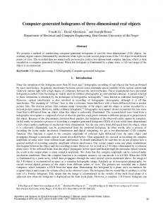
To demonstrate the proposed technique, we numerically and experimentally performed the three stages of synthesizing and testing the proposed DCH. In the first stage the desired image (containing the letters DCH) was encrypted into two phase functions by the iterative JTC-based POCS algorithm [9]. Since the SLM used in this study (CRL, XGA3) can modulate the transferred light with positive gray-tones only, the complex functions were coded into a positive real transparency. The obtained double-sections hologram was displayed on the input plane of the JTC. Each of the two sub-holograms covered only 110x225 pixels out of 600x600 pixels, as shown in Fig. 1. As we can see from this picture the coded function was located in a diagonal position in order to avoid the large zero-order diffraction occurring at the origin of the joint transform correlation output plane.
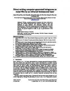
Figure I : Two sub-holograms on the JTC input plane for both the simulation and experiment. A collimated beam from He-Ne laser with h=632.8nm illuminated SLM and created a diffraction pattern of the joint transform power spectrum on the back focal plane of the first Fourierlens in the JTC set up. The entire intensity of the joint power spectrum recorded by the CCD isshown in Fig.2.
259
' '
Figure 2 : Experimental result of three diffraction orders on the joint power spectrum plane.
In the case of conealogram coding the POCS algorithm was tested with an image of the sign p as the hidden watermark pattern. Each of the two gray-tone pictures, one for hosting the watermark and the other for hosting the deciphering key, have the size of 68x68 pixels. After completing enough iterations of the POCS algorithm, the computer memory contains two continuous-tone complex-valued matrices which should be binarized according the rule of the concealogram technique [ I I]. The size of each halftone cell was 11x1 I pixels. and the gray-tone image is quantized with 7 levels of magnitude and 11 levels of phase
Two first diffraction orders on either diagonal side of the zero order can be observed. The center of the zero order is blocked in Fig. 2 for a clearer visualization. Since only one of these orders is needed, we recorded only the intensity distribution inside the frame denoted by the dashed line. The size of this frame was 795x596 pixels, and the pattern inside this frame was displayed on a second SLM. Finally, after another Fourier transform by the second lens, the correlation plane was obtained as shown in Fig. 3.
Figure 5: Two rotated CONCEALOGRAMs displayed on SLM in the optical experiment Figure 3: Experimental. result of the desired image constructed on the JTC correlation plane.
Thecenter of the zero order is also blocked in Fig. 3 for a clearer visualization. The three orders of the correlation plane and the'two images of the letters DCH in the first diffraction orders can be clearly seen, demonstrating that the proposed method has reached its goal. For comparison, Fig. 4 shows the same constructed image obtained from the-digital simulation of the process. ....'.
The same setup as in the previous experiment was used again. The two conealograms were adjusted to be displayed on the SLM. Both halftone pictures were rotated by 45 degrees on the input plane, as shown in Fig. 5, in order to avoid from the bright tails of the zero diffraction order occurring at the origin of the joint spectrum plane. A collimated beam from a He-Ne laser illuminate the SLM and created a three diffraction orders of the joint spectrum on the back focal plane of the first Fourierlens. Since only one of these orders is needed, we record only one intensity distribution inside the CCD frame. ?he captured pattern was then displayed on a second SLM. Finally, after another Fourier transform by the second Fourierlens. the correlation plane was obtained as shown in Fig. 6. Fig. 6 is the resulting watermark reconstructed from optical cross-correlation between two input concealograms. Three orders of the . correlation plane and the two images of the sign p in the first diffraction orders can be seen in the figure,
Figure 4: Simulation result of the desired image constructed on the JTC correlation plane.
260
.
demonstrating that the proposed method has reached its W"8l
Figure 6: Experimental results of the reconstructed watermark observed by the CCD on the output plane of the modified JTC. For comparison, Fig. 7 shows the same constructed image obtained from the numerical simulation of the process
in the latter, the binary mask is a figurative meaningful picture instead o f a meaningless collection of dots as the DCH. Thus, the JTC described above can be used to reveal a watermark or steganography data embedded in the concealogram. In this case, the concealogram is displayed on the input plane instead of one of the subholograms. Additionally, the main innovation in this study is that an electro-optical correlator in a modified JTC configuration deciphers the hidden information. The hidden information is revealed as a result of a spatial correlation between two CGH's or concealograms. As consequence of the above technique, illegal deciphering the hidden watermark should be practically impossible because it is hidden in the form of complicated phase function. The quality of the reconstructed watermark may be improved using alternative algorithm better than the POCS, or using SLM with more pixels. Computer simulation and optical experiment confirm our proposed technique. Since this teihnique can be particularly useful for preventing illegal distribution and since our proposed method provides the advantages o f simple design and alignment with high degree o f security the above technique can be used for versatile applications in security areas. 5. REFERENCES
Figure 7: Simulation results of the JTC output plane in which the hidden watermark was revealed.
4. DISCUSSION AND CONCLUSION We have proposed and demonstrated a new type of computer-generated hologram termed DCH. h e main purpose of the method is to construct on the output plane a complex function in a conditional way. This means that two, and only two, holograms are needed to create the complex function constructed a s a cross-correlation between the two holograms. The DCH can be used for several applications such as an encryption system where the image in the correlarion plane is considered as the information that we wish to encrypt. The sub-hologram. I modified during the POCS algorithm, is the encryptcd data, whereas the other unchanged sub-hologram is employed as the decoder for this encrypted data. When this same decoder is used in several encryption procedures, it can become a general decoder for many encrypted holograms. Placing the two sub-holograms together in the input plane o f the JTC is the only way to reconstruct the original image. This concept wds combined with the recently invented hiding information method called concealogram [I 01. The difference between the DCH and the concealogram is that
[I] W. Bender, D. Gruhl N. Morimoto, and L. Lu, 'Techniques for data hiding," IBM Sysr. J . 35, pp. 313-336, 19%. [2] D . Grover, "Steganography and watermarking of digital data." Co,rrpa~erLaw & Securiry R e p o ~ 17 r (2). pp. IOI-I04,2001. [3] S. Kishk, and B. Javidi, "3D object watermarking by'a 3 D hidden object," Opr. €.rp 11, pp. 874888,2M)3. [4] H. T. Chang. W. C. Lu, and C. J. Kuo,"Multiple-Phase remeval for optical security systems by use ofrandom- phase encoding" Appl. Opr. 41, pp. 48254834,2002. [ 5 ] D. Abkasis, 0. A m i , J. Rosen and B. Javidi, "Security optical systems based on a joint transform correlator with significantoutput," Opr. E H ~40, . pp. 1584-1589, 2001. [6] Yeh C. H.. Chang H. T., Chien H. C., and Kuo C. J., "Design of Cascaded Phase Keys for a Hierarchical Security System" Appl. Opt. 41,pp. 6128-6134,2002. [7] A. VanderLugt, "Signal detection by complex spatial filtering." IEEE Trans. It$ Theoiy IT-l0,pp. 139.146, 1964. [8] C. S . Weaver and J. W. Goodman. "A technique for optically convolving two functions," Appl. Opr. S. pp. 12481249, I%h.
[Y] J. Rosen and J. Shamir. "Application of the projection-
onto-constraint-sets algolithm for optical panern recognition," Opr. /,err. 16, pp. 752-754, 1991. [IO] J. Rosen and B. Javidi, "Hidden images in halflone pictures," Appl. Opr. 40, pp. 3346-3353,ZWl. [ I I ] A. W. Lohmann and D. P. Pans, "Binary Fraunhofer holograms generated by computer," Appl. Opt. 6, pp. 17391748, 1967.
26 1