Rene Zehnder, James H. Burge and Chunyu Zhao ..... R. Angel, J. Burge, J. L. Codona, W. Davison and B. Martin, â20 and 30 m telescope designs with potential ...
Use of computer generated holograms for alignment of complex null correctors Rene Zehnder, James H. Burge and Chunyu Zhao College of Optical Sciences, the University of Arizona 1630 E. University Blvd, Tucson, AZ 85721 ABSTRACT Large diameter, non-axisymmetric aspheric mirrors can be measured interferometrically using null correctors that employ computer generated holograms (CGHs). The testing of off axis segments for the new class of giant telescopes pose requirements that beyond the state of the art for CGHs alone. The long radius of curvature and the magnitude of the aspheric departure require other lenses and mirrors to be used along with the CGH. The alignment of these systems is very sensitive and the absolute accuracy of the alignment is critical to the system performance. We have developed techniques that use diffracted light from patterns on the CGH to accurately define the alignment of multi-element null correctors. We will present results from the null test of the 1.7-m New Solar Telescope primary mirror. The optical shape of this mirrors is an off-axis paraboloid from an f/0.7 parent. Key words: optical alignment, computer generated hologram, null testing
1. INTRODUCTION Computer Generated Holograms (CGH) have long been used in interferometric testing of aspheric surfaces.1-3 With new families of giant telescopes with off-axis aspheric primaries,4,5 the CGH alone is not enough to create the aspheric wavefront for null testing of these mirrors. The null correctors most likely consist of other refractive/reflective elements. How to align these elements to the tight tolerances typical to null correctors presents challenges. We faced this challenge when we designed the interferometric testing system for the primary mirror of the New Solar Telescope (NST) which is an off-axis segment of a paraboloid.4 The null corrector is made up of a 0.5m fold sphere and a CGH. We developed techniques to accurately align both elements in the corrector and to roughly align the NST mirror to the testing wavefront. We used CGHs for all these alignments. Since CGHs can be fabricated with high precision using laser writers, e-beam machines, etc, they make ideal tools for aligning optics with demanding tolerances. These CGHs used for alignment purpose were fabricated on the same substrate as the testing CGH, which ensures high registration accuracies. In Section 2, we give a brief description of the NST null testing system. The alignment techniques that we developed are described in Section 3. The alignment of each element – the testing CGH, the fold sphere and the NST mirror is explained in detail.
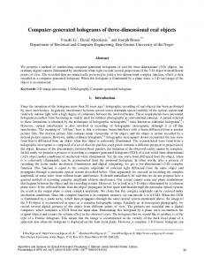
2. THE NST NULL TESTING SYSTEM Figure 1 shows the null testing system for the NST primary mirror. The NST primary is a 1.7m in diameter off-axis parabola with the parent radius of curvature of 7.7 meters and off-axis distance of 1.84 meters.6,7 The null corrector is made up of a CGH and a 0.5m fold sphere. The 3-element compound lens creates spherical wavefront to illuminate the CGH.
Optomechanical Technologies for Astronomy, edited by Eli Atad-Ettedgui, Joseph Antebi, Dietrich Lemke, Proc. of SPIE Vol. 6273, 62732S, (2006) · 0277-786X/06/$15 · doi: 10.1117/12.672139
Proc. of SPIE Vol. 6273 62732S-1
CGH
Fold sphere
Compound diverging lens
Interferometer
NST Mirror Figure 1. Illustration of the NST null testing system.
3. USE OF CGH FOR ALIGNMENT We used CGHs to align both elements of the null corrector – testing CGH and fold sphere, and the NST mirror. These alignment CGHs are all fabricated on the same substrate as the testing CGH. Figure 2 shows the scaled phase pattern plot and locations of all the CGHs on the substrate. The main testing CGH itself needs to be aligned with high precision relative to the interferometer optics. We designed a CGH to align it. It is more challenging to align the fold sphere. We used CGHs in combination with metering rods to align it. Also, we designed CGHs to create a cross hair and a clocking line to initially align the test optics to the test wavefront. Table 1 lists the spec of the substrate and Table 2 shows descriptions of each individual CGH. Table 1. The spec of the CGH substrate and description of each CGH.
Material Diameter Thickness Wedge Transmission wavefront Quality
Fused silica 100mm 9.5mm < 1 arc min