76
Context - dependent color segmentation for Aibo robots Rodrigo A. Palma-Amestoy, Pablo A. Guerrero, Paul A. Vallejos, Javier Ruiz-del-Solar, Senior member, IEEE
Abstract- Color segmentation is a key step in any colorbased robot vision system. The main factors that affect the performance of the segmentation process are the variable lighting conditions of the environment, the natural overlap between the color classes in the color space, and the distortion produced in the images by the movement of the camera and the robot. In the context of the robot soccer championship RoboCup, several segmentation approaches have been proposed, most of them based on an off-line calibration phase where a look-up table is generated for the on-line system operation. The here proposed approach employs ambiguous colors as a way of including in the calibration process the natural uncertainness of the problem. Thus, the color segmentation result is not completely defined in the calibration phase. During on-line operation a mode filter is employed for incorporating context information in the discrimination of the final class of the colors. Successful results of the application of the proposed dynamic color segmentation methodology are shown in the context of the RoboCup four-legged league. I. INTRODUCTION
Mobile robotics is a lively and expanding research field, whose main goal is the development of autonomous robots that can freely interact in dynamic environments. Some of the main tasks to be tackled are the ones of perception, navigation, dynamic map building, selflocalization, and mapping and tracking of mobile objects. These tasks are interrelated and the performance of the whole robot system depends on all of them. In this article we will focus on the segmentation of color images, a key step in color-based robot vision systems.
Manuscript received August 7, 2006. This work was partially supported by FONDECYT 1061158 project. R. A. Palma is with the Electrical Engineering Department, University of Chile, Santiago, Chile (e-mail:
[email protected]). P. A. Guerrero is with the Electrical Engineering Department, University of Chile, Santiago, Chile (e-mail:
[email protected]). P. A. Vallejos is with the Electrical Engineering Department, University of Chile, Santiago, Chile (e-mail:
[email protected]). J. Ruiz-del-Solar is with the Electrical Engineering Department, University of Chile, Santiago, Chile (e-mail:
[email protected]).
Our direct application is the RoboCup four-legged league, where Sony AIBO robots are employed. This application has some important special characteristics: (i) AIBO robots have four, 3DOF legs, (ii) AIBO odometry information is very noisy, (iii) a low-resolution color camera with 3DOF is the main employed sensor, (iv) images are obtained at 30 frames per second, (v) defined landmarks employed for localization are colored goals and beacons, (vi) field lines information can be obtained and used for localization, (vii) the ball is orange, (viii) communication between robots and with the game controller (a computer referee) is carried out using a wireless data network (802.11b), (ix) robots use blue and red uniforms, (x) no external sensing or processing is allowed, and (xi) the AIBO limited processing power causes constraints in the algorithms that can be implemented (more information about this league can be found in the RoboCup web site http://www.tzi.de/4legged). In this context, the methodology being proposed in this article solves some problems arose in the color segmentation of the images obtained by the AIBO camera. It should be stressed that having efficient color segmentation is relevant in the context of the RoboCup four-legged league, because the soccer relevant objects (landmarks, goals, players, lines, the carpet and the ball) have defined colors. We propose a dynamic segmentation system for AIBO robots, which main ideas are: (i) the use of ambiguous colors (or soft colors [5]) for handling the uncertainties introduced in the process of color calibration, and (ii) the use of a mode filter for using context information in the discrimination of the final class of the colors. This article is organized as follows. In section 2, the operation of our vision module is described. The proposed dynamic segmentation system for AIBO robots is presented in section 3. In section 4, preliminary results of the operation of the proposed system are presented. Finally, in section 5, some conclusions of this work are discussed.
1-4244-0537-8/06/$20.00 ©2006 IEEE
128
76
2
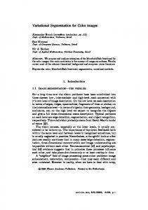
Fig. 1. Scheme of the vision module of the team Uchile1.
II. RELATED WORK
Different approaches have been used to solve the visual processing and color segmentation problems in the RoboCup four-legged league. Some teams have implemented visual systems where the received images from the camera are completely processed and segmented [8][9], while others have used scan lines based methods where only these scan lines are segmented [6]. In both cases is important to have good color segmentation module. For implement the color segmentation process, several approaches have been used to classify the pixels in color classes in and out of Robocup framework: clustering in YUV space with k-means [10], distances between each pixel and center of the classes altogether with color table [6], color segmentation with soft colors and soft blobs [5], edges detectors and color table segmentation systems [2][11]. In addition to the color segmentation approaches, some techniques of pre-processing and color representation have been developed in order to make color [12] and image transformations to reduce the illumination dependence in the images. For example, Retinex based algorithm [13][14], ACE
based algorithm [15]. The problem with these techniques is that they are not necessary real time development. Our approach uses a soft color table and an efficient implementation of a mode filter to add information of context to the final color segmentation, in order to deal with these problems, but focusing on real time. III. UCHILE1 VISION MODULE
A. General Description The vision module implemented by the UChile1 team, behaves according to the flowchart shown in figure 1. Accelerometers and encoders. This module reads the robot accelerometers and encoders. Accelerometers are placed in the robot’s body while encoders sense the positions of the robots legs and neck articulations. Image. This module captures the images from the video camera of the robot. Camera position. This module uses the information of the accelerometers and encoders to compute the transformation
129
76
3
between camera and robot coordinate systems. This transformation and its inverse are used in the perceptors and visual sonar modules which are described later. Color Segmentation. This stage receives an image from the robot video camera and classifies its pixel as belonging to any of the interesting color classes. This is implemented using a color table, generated in the system calibration phase, where each YUV pixel appears associated to some class of interest. As can be seen in the scheme, segmentation is fundamental for the performance of the vision module. It influences all the following stages of the system, due to color segmented images are used in the blobs formation, visual sonar and perceptors modules. Blobs formation. In this stage, connected pixels belonging to the same color class are grouped together and merged into a single structure called blob. For each blob, several statistics, of the corresponding pixel set are calculated and stored. Some of them are: weight (number of pixels), mass center (average pixel position), bounding box, and points of interest, such as corners and borders. Visual sonar. This stage aims to detect field lines, obstacles and robots. Instead of using blobs, it searches for the desired objects using a mesh of scanning lines [6]. More precisely, the visual sonar searches for every point in the mesh that may belong to a border of a desired object. The resulting set of border points candidates is used in a later stage to detect the desired objects. A border point candidate is defined as a pixel having a large luminosity change or certain color transition from the previous pixel in the scanning line it belongs to. Lines and obstacles perceptors. These modules try to detect lines and/or obstacles from a set of border point candidates obtained in the visual sonar. For performing this, they group sets of points fulfilling specific rules for each desired object. For instance, a set of border point candidates (projected to the field plane) must satisfy a straight line equation to be recognized as a field line. Ball, beacons and goals perceptors. These perceptors detect the desired objects from the blobs obtained in the Blob Formation Module. For detecting an object, specific rules are applied to each blob, or pair of blobs, having the color classes of the object. For example, a yellow-pink beacon is detected, when two blobs, one yellow and the other pink, and their statistics fulfill a set of specific rules. Ball scanning lines. The aim of this stage is to characterize the ball candidates obtained in the ball perceptor stage. For performing this, a set of ball border point candidates are collected using a set of radial scanning lines. The mass center of the corresponding orange blob is used as the center of the radial scanning lines. A ball border point candidate is defined as a pixel having certain color class transition from the previous pixel in the scanning line. A least squares based algorithm determines the radius and the center of the ball in the image. Again, some rules need to be fulfilled for the ball candidate to be accepted. It is in this sense that this stage filters ball candidates. B. Color segmentation The color segmentation system consists of two independent stages: offline calibration and online operation.
Fig. 2. Offline training system.
Fig. 3. Yellow pixels are selected and indicated to the system that they are of this class.
Fig 4. Spatial YUV distribution of yellow class.
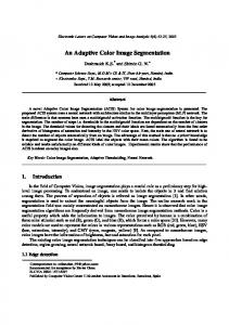
The system calibration consists in the creation of a segmentation table. In this process several images captured from the robot camera are used. Figure 2 shows the software interface used to implement this task, where each image is showed to a human operator. The human must select manually each region of pixels in the image having any interesting color class and then associate the corresponding class to the region. In figure 3, the procedure is shown. The yellow goal is selected and then it is indicated to the system that the pixels belong to the “YELLOW” class. These inputs are used by the system to create a threedimensional table, as shown in figure 4, where each coordinate corresponds to a pixel value in one of its (Y,U,V) components, and the value stored in each cell is the color class to which the corresponding YUV vector belongs to.
130
76
4
During the online operation stage, each image pixel is associated to the class stored in the color table position having the same coordinates as the pixel’s YUV value. It is important to say that nothing assures that the pixels will be classified correctly in the online system operation stage, because the variable lighting conditions and the camera noise may change the pixels value. Nevertheless, an intensive calibration will yield better results than calibrating with few images. In addition, a filtering operator applied over the segmented image or in the color table can be implemented for robustness against blur and changing lighting conditions. This approach has been used [7] for online calibration. IV. PROPOSED SYSTEM
Fig. 5. Color table obtained form an exhaustive training.
A. Problem Definition As stated above, color segmentation is a very relevant stage in UChile1 vision system. The main problem in color segmentation is related to the confusions between color classes. These confusions are caused by lighting conditions changes and image distortion. As a result, we can observe a same pixel YUV value in objects of different colors. Living organisms with advanced visual systems face the same problem, but they use, for each pixel, its context information in the image to differentiate between one color and other. As an example, we show, in figure 5, a color segmentation table obtained from a set of 100 training images. Most of the pixels belonging to the interesting color classes were used to obtain the table. White color dots are plotted black to make them visible. From observing figure 5 we notice two important facts: first, all pixels belonging to interesting color classes are grouped in a determined region of the YUV space. Second, these regions intersect one another. From these two facts, one can conclude that it is impossible to make a “perfect” training in which every pixel is uniquely classified; color confusions are inherent to the problem. To show more clearly the problem and the proposed solution, we will analyze the confusions between two colors which are very often confused in this application: orange and red. Figure 6 shows a segmentation table for only these two colors. Figure 7 shows the intersection between red and orange. When facing a pixel YUV value which is not uniquely classified, a conventional segmentation system will be forced to decide whether a pixel belong to one or the other class. One can try to improve the training process to make this decision optimal. Nevertheless, we think it is better to keep this uncertainty in the color table and then, in the online segmentation process, for each pixel belonging to ambiguous classes, use the context information to take the final decision. Thus, the system proposed in this work incorporates a mechanism to deal with uncertainty in segmentation from offline training to online working stages.
Fig. 6. Red and orange color table
Fig. 7. Intersection between red and orange classes.
B. Histograms As training process is made offline, one can count with huge computational resources in this stage compared with the working stage, which must be done online and with a less powerful hardware. For that reason, we tried to make the complex part of the process as much as possible in the training stage. Instead of generating a unique color segmentation table in the training process, we count the repetitions of each YUV value been classified as belonging to each color class. This process can be seen as constructing histograms for each color
131
76
5
class. This idea is implemented using one color table for each color class, where the value stored in each YUV position corresponds to the number of associations made between pixels having this YUV value and the color class of the table. The histogram of color class k is defined as:
classes are sorted from those having more repetitions to those having less. The first class is always selected. We now calculate a relative importance of the second class respect to the first. That importance is calculated as follows: ω=
H k (P)
with
k = 1,2,....,8 , and
P = ( Py , Pu , Pv ) ,
pixel
P.
Then
is the number of times that a pixel P was classified as belonging to k. We can now define, for each YUV vector P , its histogram HP as follows: H k ( Py , Pu , Pv )
H p (k ) = H k ( P )
Note that there is one histogram of this kind for each YUV vector and each histogram has one bin for each color class. This first stage contributes with very important information for the rest of the process. It will allow us to determine the relative belonging importance of each pixel to each color class. One could figure many ways to use this further information in the working stage but it must be reminded that computational resources are a strong limitation in that stage. Thus, the main part of this proposal is how to communicate and use this information with a low computational cost. C. Soft colors Once histograms are filled out, the system automatically processes them to generate a single table where the information is summarized. This table has a format which allows the online system to efficiently handle it. The idea is that each YUV value is now able to belong to more than one class. The implementation is very simple: in each YUV position in the table, there is a byte, in which each bit represents the belonging of this YUV color to a color class. Let T ( Py , Pu , Pv ) = b1b2b3b4b5b6b7b8 be a color table that for each YUV color, P = ( Py , Pu , Pv ) , returns a byte. If P belongs to the class k, then bk is set to 1, else, bk is set to 0. As a result, a single YUV color can belong simultaneously to as many classes as necessary. To decide whether a YUV color belongs to a class the histograms information is used. In this codification, classes are sorted from the most frequent to the rarest. This order is set in calibration time and has two objectives: to make posterior operations more efficient and to keep more information which could be used if necessary for discriminating between classes. In our particular application, confusions between more than two colors are very rare. For that reason, we limited the belonging of one YUV color to a maximum of two classes. Nevertheless, the reader should note that this limitation does not determine the rest of the process and, thus, the system is not limited to applications with this particular condition. Every YUV color that has a non empty histogram belongs to one or two classes. The classes to which a YUV color belongs are chosen as those having more repetitions in the respective histogram. If the histogram of the YUV color has more than one non empty bin, a simple rule is used to decide whether the pixel belongs to one or two classes. The
H P (k ) H P (k ) + H P (l )
where k and l are the first and the second classes respectively. If ω is over a threshold, then the second class is included. The selected threshold value is 20%. The resulting table is called soft colors table as it allows the existence of uncertainty in color classification. By using this procedure we accomplish to pass the segmentation uncertainty to the online working phase. In that phase, the uncertainty is going to be vanished using the pixel’s context information. The color uncertainty and the pixel’s context information can be used in different ways to obtain a final segmentation for the pixel. In this work, we propose a simple and efficient procedure, based in a mode filter, to do this task. D. Mode filter We can now make a new segmentation using the soft colors table. This segmentation will produce a soft colors segmented image in which each pixel may be classified as belonging to up to two classes. This image can be useful itself but it is also interesting to obtain a unique color segmented image. In this point, the information provided by the pixel’s context becomes useful. Multiple solutions to integrate the context information have been proposed which not necessarily excludes one another [5]. Differing from the methods that identify objects borders, we implemented a simple and general method, which uses a mode filter to take in account the pixel’s context information. The filter applied consists in a 3x3 pixels window which runs across the whole image. We can define the problem in the following terms: Let I be the original image obtained from the camera, Pi j = I (i, j ) the pixel value Pij = ( Py , Pu , Pv ) in the (i, j) position of I, IC (i , j ) the soft colors segmented image, IF (i, j ) the mode filtered image, and V3x3 (i, j ) the window centered in the I(i, j) pixel. It is important to note that V3 x3 (i, j ) corresponds to the pixel IC (i, j) and its 8 neighborhoods. The images IC and IF are calculated as follows: IC (i, j ) = T ( I (i, j ))
where T is the color table. To generate this image we simply apply the soft colors table to the original image. Each pixel IC (i , j ) will have as value a bit run in which each bit corresponds to the belonging of the pixel to certain color class. The next step aims to make a single color classification for each pixel i.e. it generates IF. Each pixel in IF has a value in {1, 2, 3, 4, 5, 6, 7, 8} that represents the class to which the pixel belongs. To obtain this single class from the soft colors representation, we use a mode operator which considers the neighborhoods information. IF (i, j ) = Mode(V3 x3 (i, j ))
132
76
6
The operator Mode(W ) , calculates the mode of the pixel set contained in the window W, counting one point for each class k every time a pixel in W belongs to k. As a result, the pure colors tend to remain unaltered and, in the regions of the image where ambiguous colors appear, the pure color neighborhoods will determine the classification of the ambiguous pixels. When two or more colors have the same number of repetitions over the filter window, the mode filter could result in more than one class. In this case, the system makes an arbitrary decision: to take the class having the minor index form the candidates, which, as we have previously seen, should be the most frequent class in the environment. The mode filter is a very time consuming operation. As computational resources are limited in the hardware platform we are using and the system must work in real time, the mode filter must be implemented in an efficient way. For performing that, we implemented a mobile counter based system. Six pointers are moved together along every three consecutive rows of the image. Two pointers point to each row of the 3x3 filter window, one of them (input pointer) increments and the other (output pointer) decrements the counter of each class to which the pointed pixel belongs. As the window moves counters are maintained without necessity of counting classes on every 9 pixels each time. A second, and perhaps more important, optimization is the use of efficient bit operations for counting classes from the bit array and the use of an optimum order in the class bit array. V. RESULTS
We captured a video from an AIBO robot camera in continuous movement. Selected frames from this video are used in the system tests. One of the most frequent color confusion in the RoboCup competitions environment is between orange and red colors because of its proximity in the YUV space. Considering this fact, this analysis focused on the results obtain when applying the implemented system to the segmentation of those colors. In the calibration process, objects present in the video images are carefully selected in order to obtain its borders. Spotlights and color variations present inside the objects are also selected as part of the objects, because is too difficult to discriminate if those pixels belong to one specific class, but it is clear that they belong to the interesting objects. In order to show the described problems in the previous chapters, each of the two mentioned colors is calibrated on independents look up tables. Afterwards, each remaining color is calibrated on the corresponding look up table, without overwriting already classified pixels. With this, we have two possible look up tables, depending of which pixel is firstly calibrated. Later, it is shown the system trained with the same images, but using histograms and soft colors. Next, a square mode filter will be applied. Finally, remaining colors will be calibrated to show that classification errors obtained with the system trained with only two colors are drastically reduced when the system is trained with all colors.
Fig. 8. Some images used for red calibration.
Fig. 9. Red color distribution in the YUV space after training.
Fig. 10. Image segmentation with a look up table calibrated only with red color. Left: Original image. Right: Segmented image.
Some images selected for the red color calibration are shown in figure 8. The look up table generated with this color alone is shown in figure 9. The images in the figure 10 show what happens when the orange color is present but not yet calibrated. In order to see the effect of the other confusion color segmentation, orange color is calibrated using a new empty look up table. Some images used in the training are shown in
133
76
7
figure 11. The look up table generated for the orange color is shown in figure 12. The lower image in figure 10 is segmented using the look up table acquired with the orange color training. In order to see the effect of the orange training in the red color, this image and a second example are shown in figure 13.
Fig. 13. Image segmentation with a look up table calibrated only with orange color. Left: Original image. Right: Segmented image.
Fig. 11. Some images used in the orange calibration.
Fig. 12. Orange color distribution in the YUV space after training.
Using the same training images, a look up table is generated training orange and red colors without overwriting already classified pixels. Hence, if the red color is the first color to be classified, then when the training for orange color takes a pixel already classified as red, the result classification will be red independent of the real color class. The effect of this look up table is shown in figure 14. This procedure is repeated, but training first the orange color this time. Figure 15 shows some of the training images. These images show the intrinsic color segmentation problem due to the color confusions. The test used a no overwriting restriction when training the look up table and this restriction could have made the problem worse. Without this restriction the segmentation would be wrong anyway, because the system would still have a single class for each pixel.
In figure 16, the segmentation of these two colors using soft colors is shown. Some of the regions previously classified as red or orange are now displayed in a light pink. This is the adopted way to present a soft color. The main advantage of having an image with more than one class for pixel, is on the possibility of to discriminate the final class according to other information levels, for example distinguishing borders of the image [2][4]. Afterwards, the mentioned mode filter is applied in the system with soft colors, and in the system without soft colors, results are shown in figure 17. The segmentation results with this two images groups show that the use of the mode filter over the soft colors segmentation allows a better classification of the pixels based on the context. The upper images show that in the cases of the orange ball region and of the red robots uniform, the color classification is determined adequately, generating a satisfactory segmentation. Lower images show that a mode filter when applied without soft colors is not enough to obtain a good segmentation, because the orange regions inside the uniforms and the red regions inside the ball are enlarged due to the filter.
Fig. 14. Orange segmentation over red segmentation without pixel overwriting.
Fig. 15. Red segmentation over orange segmentation without pixel overwriting.
134
76
8
Fig. 16. Color segmentation using soft colors. On all images there are ambiguous classes displayed as light pink in the confusion sectors.
Fig. 17. Upper images: Soft colors with mode filter. Lower images: pure colors only with mode filter.
Finally, it has to be noticed that in the image there are many white zones classified as orange. This happens because of the coincidence with the YUV values on the ball spotlights. However, it is expected that the soft colors resolve this problem, when the white color is calibrated, in the same way they did in the case of the red and orange confusion. Figure 18 shows the results of a fast calibration with all the colors and is compared with the results of the system without soft colors and without pixels overwriting. It is clearly seen that the resulting color segmentation is excellent in the analyzed image. There is no important confusion in any color due to the mode filter application and the soft color implemented.
Fig. 18. Fast calibration including all colors. Left: captured image. Center: image with soft colors and with mode filter. Right: image without soft colors and with mode filter. VI. CONCLUSIONS
The color segmentation on systems with video cameras, in low controlled lighting conditions environments, can be a hard problem due to several reasons. Variability on illumination, distortion produced by the camera movement and the low sensor resolution, make possible that a single pixel value appear in objects of different colors. This work corroborates this fact, training the system with two usually confusing colors and observing the generated classes in the YUV space. The results make evident the intersections between these classes. Once the problem causes are identified, the basis of the proposed system is that the only way of discriminating between two intersecting classes is to use another kind of information further than the pixels value. This information has to be extracted from the context of the pixel in the image. In this way, the here proposed approach, where part of the uncertainty is exported to the on-line system and a mode filter is used to solve the ambiguity, contribute significantly to the problem solution. The carried out experiments show the improvement on the color segmentation in the on-line stage generated by the implemented system. Colors are clearly
differentiated and false classifications are eliminated on stable lighting conditions. The implemented system shows a strong improvement in the segmentation of images with camera motion distortion, because if the system is trained with images having camera motion distortion, ambiguous colors naturally appear in the distortion area, and, by filtering, the right color can be obtained in the on-line system. In variable lighting conditions, the system did not yield significant improvements. In order to face those environments, it is proposed study transformations in the look up tables that allow the segmentation system adapting automatically to the lighting conditions in every moment. One of the main considerations in this work was the processing time. The application of the mode filter, and the coexistence of more than one classes for each pixel, were developed with emphasis in the code optimization, keeping the system being able to run at 60 frames by second in this stage, and keeping the whole vision system running at 30 frames per second. The results obtained by the implemented system allowed us to replace the old segmentation system used by the UChile1 team, and the new one was used on the RoboCup 2006 competition. It is important to notice that mode filtering is just a first approach in order to use the soft colors in the system. The benefit generated for the existence of this ambiguity may be much more extensive, and it should be used in further system stages. As a future work, it is proposed to keep exploiting the potentialities of soft colors, for example, using them in conjunction with border detection to determine the final pixel color class. On the other hand, it is proposed to extend the blob generation to soft color blobs. In such an approach, the object recognition stages could verify rules for normal color blobs and rules for soft colors blobs (soft colors use to appear in determined places inside an object with most of its area filled with its normal color [5]). We strongly believe that this will lead to a better object recognition and characterization. Another important matter we are still working on is the amount of time required for calibration. We are planning to use some pattern classification procedure, at least in a first stage of calibration, to make it faster. REFERENCES
[1]. Javier Ruiz-del-Solar, Paul Vallejos, Raúl Lastra, Patricio Loncomilla, Juan Zagal, Carlos Morán and Iván Sarmiento. “UChile1 Technical Report”. Electrical Engineering Department. University of Chile. In: http://www.robocup.cl/, 2005. [2]. Craig Murch and Stephan Chalup. “Combining Edge Detection and Colour Segmentation in the Four-Legged League”. In: Proc. of the Australian Robotics and Automation Association, 2003. [3]. Nathan Lovell. “Illumination Independent Object Recognition”. In: Proc Notes in Computer Science, p. 384-395, 2005. [4]. Zbigniew Wasik and Alessandro Saffiotti. “Robust Color Segmentation for the RoboCup Domain”. In: 16th
135
76
[5].
[6]. [7].
[8]. [9]. [10].
[11].
[12].
[13]. [14].
[15].
9 International Conference on Pattern Recognition (ICPR'02) , volume 2, p. 20651, 2002. Michael Quinlan et al. “NUbots Team Report”. School of Electrical Engineering and Computer Science. The University of Newcastle. In: http://www.robots.newcastle.edu.au, 2005. Thomas Röfer et al. “German Team Technical Report”. Center for Computing Technology, Bremen University. In: http://www.germanteam.org, 2005. Matthias Jüngel, Jan Hoffmann and Martin Lötzsch. “A Real-Time Auto-Adjusting Vision System for Robotic Soccer”. Lecture Notes in Computer Science, Volume 3020, p. 214-225, 2004. Hayato Kobayashi, Akira Ishino and Ayumi Shinohara. “Jolly Pochie Team Description Paper”. Department of Informatics, Kyushu University, 2005. Tamio Arai. “ARAIBO Technical Report”. University of Tokyo and Chuo University, 2005. Gerd Mayer, Hans Utz and Gerhard Kraetzschmar. “Towards Autonomous Vision Self-Calibration for Soccer Robots”. In: Proceedings of the 2002 IEEE/RSJ Intl. Conference on Intelligent Robots and Systems, p. 214-219, 2002. A. Koschan and M. Abidi, "Detection and Classification of Edges in Color Images," In: Signal Processing Magazine, Special Issue on Color Image Processing, Vol. 22, No. 1, pp. 64-73, 2005. H.J. Trussell, E. Saber and M.Vrhel. “Color image processing [basics and special issue overview]” In: Signal Processing Magazine, IEEE, Vol 22 N°1 pp. 1422, 2005. EH. Land, JJ. McCann. “Lightness and retinex theory”. In: J Opt Soc Am. 61(1):1-11. 1971. Edoardo Provenzi, Luca De Carli, Alessandro Rizzi, and Daniele Marini, “Mathematical definition and analysis of the Retinex algorithm”, JOSA A, Vol. 22, Issue 12, pp. 2613-2621, 2005. A. Rizzi, C. Gatta, D. Marini: “A new algorithm for unsupervised global and local color correction”, Patt. Rec. Lett. 124, 1663-1677, 2003.
136