Cinderella obeyed, ... As, however, Cinderella went on asking, ..... one million inhabitants, the city of Yogyakarta is situated just 28 km to the south of the active.
Institut für Geowissenschaften, Universität Potsdam
Continuous Automatic Classification of Seismic Signals of Volcanic Origin at Mt. Merapi, Java, Indonesia
Dissertation
zur Erlangung des akademischen Grades Doktor der Naturwissenschaften (Dr. rer. nat.) in der Wissenschaftsdiziplin Geophysik
eingereicht an der Mathematisch-Naturwissenschaftlichen Fakultät der Universität Potsdam
von Matthias Ohrnberger geboren am 14.05.1968 in Murnau am Staffelsee
Potsdam, im April 2001
Als Dissertation genehmigt von der Mathematisch-Naturwissenschaftlichen Fakultät der Universität Potsdam
Tag der mündlichen Prüfung:
3. Juli 2001
Vorsitzender der Prüfungskommission: Professor Dr. R. Oberhänsli Institut für Geowissenschaften Universität Potsdam Erstberichterstatter: Professor Dr. F. Scherbaum Institut für Geowissenschaften Universität Potsdam Zweitberichterstatter: Professor Dr. J. Zschau GeoForschungsZentrum Potsdam Drittberichterstatter: Professor Dr. M. Joswig Department of Electrical Engineering Tel Aviv University
... Cinderella obeyed, but wept, because she too would have liked to go with them to the dance, and begged her step-mother to allow her to do so. “Thou go, Cinderella!” said she. “Thou art dusty and dirty, and wouldst go to the festival? Thou hast no clothes and shoes, and yet wouldst dance!” As, however, Cinderella went on asking, the step-mother at last said, “I have emptied a dish of lentils into the ashes for thee, if thou hast picked them out again in two hours, thou shalt go with us.” The maiden went through the back-door into the garden, and called, “You tame pigeons, you turtle-doves, and all you birds beneath the sky, come and help me to pick The good into the pot, The bad into the crop. Then two white pigeons came in by the kitchen window, and afterwards the turtle-doves, and at last all the birds beneath the sky, came whirring and crowding in, and alighted amongst the ashes. And the pigeons nodded with their heads and began pick, pick, pick, pick, and the rest began also pick, pick, pick, pick, and gathered all the good grains into the dish ...
cited from Cinderella in: Grimm’s Household Tales, Translation by Taylor, Edgar in 1812, Original tale: Aschenputtel (first published in 1812) by Wilhelm Grimm (*1786, Hanau - ✝1859, Berlin) and Jacob Grimm (*1785, Hanau - ✝1863, Berlin)
Acknowledgments While working on this thesis I have received continuous support from all people around me, especially from my family, my friends and colleagues. Most important to me was the love and the support of my wife Veronica and my family during all these years. Despite my frequent absence, both physically as well as mentally, they have always been comprehensive and patient. I could rely always on their encouragement and assistance. Therefore, I want to dedicate this thesis to Veronica and my parents Christa and Friedrich. I want to express my gratitude to my supervisor Frank Scherbaum. Since entering his working group eight years ago I have always been happy to work with him. Besides enjoying his scientific advice and kind guidance during my thesis, I have especially appreciated his open door, his good mood, and his optimistic way of thinking. Frank Scherbaum’s open mindedness has been the basis for this thesis allowing myself to develop and follow my own ideas. I owe him thanks for his confidence and his patience. Additionally, I am indebted to his efforts in finding financial support for the attendance of several conferences. I owe special thanks to my friend and colleague Joachim Wassermann. Indeed he is the one to be blamed for me working on this thesis. His studies at Etna and Stromboli roused my interest in the field of volcano seismology and the unforgettable field campaign at Mt. Etna finally triggered my involvement in this special field of seismology. I am especially grateful for his friendship throughout these years, frequent discussions, and the common experiences of the ups and downs during the fieldwork in Indonesia. Joachim also helped to improve the manuscript of this thesis by critical reading of premature versions. All members of the Geophysics group at University of Potsdam have contributed to this work. Joachim Wassermann, Frank Krüger and Andreas Rietbrock have given advice and suggestions and the discussions have been always interesting and also often passionate. There has never been a lack of ideas, rather the converse, which is best reflected by Frank’s standard introductory phrase: “Wouldn’t it be fairly easy to ...”. I thank E. Schmidtke for her assistance and efforts in Earthworm related programming issues and Daniel Vollmer for his work regarding the design, construction and repair of field equipment. I am also indebted to our colleagues in Indonesia. Their help during the field work at Mt. Merapi and their constant efforts in maintaining the seismic station network has been essential for the project. Special thanks are dedicated to Drs. Budi and the head of the Geophysics Laboratory at the Gadjah Mada University, Dr. Kirbani. Further thanks are given to the staff of the Volcanological Technology Research Center (VTRC, the former Merapi Volcano Observatory MVO) of the Volcanological Survey of Indonesia (VSI) in Yogyakarta. Dr. S. Rizal and Dr. A. Ratdomopurbo is given thanks for their allowance to use the installations of VTRC. During my stays in Indonesia I appreciated very much the discussions about Merapi’s seismic signals with Dr. A. Ratdomopurbo and his general explanations about Merapi. Pak Made has provided important help in technical and logistic matters. Not to be forgotten is Dr. A. Brodscholl. He gave support and helping hands wherever he could.
This work was kindly supported by the Deutsche Forschungsgemeinschaft DFG under grants Sche 280/9-1,2,3 and the GeoForschungsZentrum Potsdam (GFZ). Additional funding for several field trips to Indonesia have been provided by the GeoForschungsZentrum Potsdam (GFZ) and the International Bureau of the Federal Ministry of Education and Research (Bundesministerium für Bildung und Forschung, BMBF). All graphics have been produced with the Generic Mapping Tools (GMT), written and freely distributed to the scientific community by Paul Wessel & Walter H.F. Smith. The programs for the hidden Markov modeling have been based on a freely available tutorial example code written by J. Picone from the Institute of Signal and Information Processing (ISIP) of the Mississippi State University. Computer code for the vector codebook learning has been adapted from the work of A.J. Robinson from Cambridge University Engineering Department (UK).
Table of contents
Table of contents
1. Abstract
1
2. Introduction
5
3. Seismic signals of volcanic origin
9
3.1. Overview of volcano-seismic signals and terminology
10
3.2. Seismic signals at Merapi volcano
14
4. Pattern recognition for seismic signal classification
19
4.1. Definition of pattern recognition
19
4.2. Detection and classification by statistical pattern recognition
20
4.3. Elements of a pattern recognition system
21
4.3.1. Feature generation and selection
23
4.3.2. Classifier design, decision rule and data learning
26
4.3.3. System evaluation
32
4.4. Review of pattern recognition methods applied in seismology
34
4.5. A novel strategy for the classification of volcano-seismic signals
37
5. Hidden Markov models
39
5.1. First-order discrete Markov processes
39
5.2. Extension to discrete hidden Markov models
40
5.3. The three problems for hidden Markov models
41
5.3.1. Solution to the evaluation problem
42
5.3.2. Solution to the problem of the optimal state sequence
45
5.3.3. Solution of the training problem
47
5.4. The use of hidden Markov models in classification problems
51
i
Table of contents
5.5. Practical considerations for the design of a hidden Markov model classification system 52 5.5.1. Production of discrete observation sequences by vector quantization
52
5.5.2. Model dimension and model topology
54
5.5.3. Initialization of seed models for hidden Markov model training
57
6. Passive seismological experiment at Merapi volcano
59
6.1. The seismic monitoring network at Merapi volcano
59
6.2. Description of available data set
63
7. Realization of a continuous automatic classification system for volcanoseismic signals at Merapi volcano 71 7.1. Parametrization of continuous three component seismic data streams in combined network/array geometry 71 7.1.1. Broadband frequency wavenumber analysis (bbfk-analysis)
72
7.1.2. Polarization Analysis
75
7.1.3. Sonogram Calculation
77
7.2. Analysis of wavefield parameters for the classification system
79
7.2.1. Robustness of signal estimates
81
7.2.2. Class-dependent feature characteristics and distributions
84
7.2.3. Feature vector used for classification
89
7.3. Training of vector codebooks 7.4. Training of classification
discrete
hidden
93 Markov
models
for
seismic
7.5. Continuous automatic classification of volcano-seismic signals
8. Discussion of results
signal 95 108
113
8.1. Evaluation of system performance
113
8.2. Behavior of system for unknown signals
124
8.3. Possible improvements of system performance
128
9. Conclusion
131
10. References
135
ii
Table of contents
11. Appendices A Mathematical definitions in the context of pattern recognition
149 149
A.1 Distribution and density functions of a random vector
149
A.2 Moments of distributions
150
B Accounting for the dynamic range of computations in the evaluation and training of hidden Markov models 152 C Implementation of DHMM-based classification-system into the real-time seismic analysis environment Earthworm 154
iii
Table of contents
iv
CHAPTER 1.
Abstract
The island of Java (Indonesia) belongs to the most densely populated regions on earth. Around two million inhabitants of this island live permanently under the risk of volcanic eruptions originating from one of Java’s 35 active volcanoes. Among those, Merapi volcano, located in the central part of the island, is the most feared, owing to its almost continuous activity and its especially dangerous eruptive style. Merapi’s high-risk potential is the cause for concentrated national and international research efforts in the field of volcano monitoring. Due to the close relationship between the volcanic unrest and the occurrence of seismic events at Mt. Merapi, the monitoring of Merapi’s seismicity plays an important role for recognizing major changes in the volcanic activity. An automatic seismic event detection and classification system, which is capable to characterize the actual seismic activity in near real-time, is an important tool which allows the scientists in charge to take immediate decisions during a volcanic crisis. In order to accomplish the task of detecting and classifying volcano-seismic signals automatically in the continuous data streams, a pattern recognition approach has been used in this work. It is based on the method of hidden Markov models (HMM), a technique, which has proven to provide high recognition rates at high confidence levels in classification tasks of similar complexity (e.g. speech recognition). The HMM-based classification of volcano-seismic event types represents a novelty in the field of seismology. It is used in its simplest form, the discrete hidden Markov model (DHMM). A prerequisite for any pattern recognition system is the appropriate representation of the input data in order to allow a class-decision by means of a mathematical test function. Based on the experiences from seismological observatory practice, a parametrization scheme of the seismic waveform data is derived using robust seismological analysis techniques. The special configuration of the newly installed digital seismic station network at Merapi volcano, a combination of small-aperture array deployments surrounding Merapi’s summit region, allows to parametrize the continuously recorded seismic wavefield with array methods. The signal parameters are analyzed to determine their relevance for the discrimination of seismic event classes. As best suited for the continuous automatic classification of volcano-seismic signals, the following set of short-term seismic wavefield parameters is obtained in a sliding window-analysis at each array site: maximum waveform coherence and beampower via a broadband frequency wavenumber analysis; the
1
Abstract
incidence angle of an array-wide averaged polarization ellipsoid; a set of short term spectral power estimates (sonogram) computed from the array-wide averaged amplitude spectra. All wavefield parameters are summarized into a real-valued feature vector per time step. The time series of this feature vector build the basis for the DHMM-based classification system. By applying a de-correlating and prewhitening transformation and further vector quantizing the feature vectors with a previously trained vector codebook, the seismic wavefield can be represented as an abstract, discrete symbol sequence with a finite alphabet. This sequence is subject to a maximum likelihood test against the discrete hidden Markov models (DHMMs), which have been learned from a representative set of training sequences for each seismic event type of interest. A time period from July, 1st to July, 5th, 1998 of rapidly increasing seismic activity prior to the eruptive cycle between July, 10th and July, 19th, 1998 at Merapi volcano is selected for evaluating the performance of this classification approach. Three distinct types of seismic events according to the established classification scheme of the Volcanological Survey of Indonesia (VSI) have been observed during this time period. Shallow volcano-tectonic events VTB (h < 2.5 km), very shallow dome-growth related seismic events MP (h < 1 km) and seismic signals connected to rockfall activity originating from the active lava dome, termed Guguran. For each of the three observed event types a set of DHMMs have been trained by the Viterbi algorithm using a selected set of seismic events with varying signal to noise ratios and signal durations. Additionally, two sets of discrete hidden Markov models have been derived for the seismic noise, incorporating the fact, that the wavefield properties of the ambient vibrations differ considerably during working hours and night time. In a first step, the recognition capabilities of the DHMM-based classification approach are evaluated by re-classifying the set of training samples (resubstitution method), providing an optimistic estimate of the true classification error. The recognition performance shows an almost optimal recognition rate of 99 %. For the continuous recognition of volcano-seismic events in the time period between July, 1st to July, 5th, 1998, the continuously recorded digital network data is parametrized and converted to a discrete symbol sequence. Partial symbol strings are extracted from the symbol sequence in a sliding window and tested against the available set of discrete hidden Markov models. The outcome of the maximum likelihood test functions for each individual model is evaluated following two different strategies. The time segment under consideration is classified a) to that seismic signal class which is represented by the model providing highest probability, or b) to that seismic event type, whose complete set of models provides the best average probability in the maximum likelihood test. It is found, that the best performance of the classification system is achieved when the average probability of all models corresponding to one signal class is evaluated. By further pruning the automatic detection list from too short detection windows, a total recognition accuracy of 67 % is obtained. The mean false alarm (FA) rate can be given by 41 FA/class/day. However, variations in the recognition capabilities for the individual seismic event classes are significant. Shallow volcano-tectonic signals (VTB) show very distinct wavefield properties and (at least in the selected time period) a stable time pattern of wavefield attributes. The DHMM-based classification performs therefore best for VTB-type events, with almost 89 % recognition accuracy and 2 FA/day. Seismic signals of the MP- and Guguran-classes are more difficult to detect and classify. For the 5-day period under consideration, around 64 % of MP-events and 74 % of Guguran signals are
2
Abstract
recognized correctly. The average false alarm rate for MP-events is 87 FA/day, whereas for Guguran signals 33 FA/day are obtained. However, the majority of missed events and false alarms for both MP and Guguran events (especially short-lasting, low energetic Guguran events) are due to confusion errors between these two event classes in the recognition process. The confusion of MP and Guguran events is interpreted as being a consequence of the selected parametrization approach for the continuous seismic data streams. The observed patterns of the analyzed wavefield attributes for MP and Guguran events show a significant amount of similarity, thus providing not sufficient discriminative information for the numerical classification. The similarity of wavefield parameters obtained for seismic events of MP and Guguran type reflect the commonly observed dominance of path effects on the seismic wave propagation in volcanic environments. The propagation medium at volcanoes is known to be composed of heterogeneous and thin layers of unconsolidated materials resulting in a complicated, highly-attenuating threedimensional structure with rough topography. Thus, as MP-type events as well as Guguran signals are generated very close to the surface and nearly at the same location of the volcano (active lava dome region), the seismic wavefield observed at some distance to the shallow source region of MP and Guguran events is dominated by path effects. The recognition rates obtained for the five-day period of increasing seismicity show, that the presented DHMM-based automatic classification system is a promising approach for the difficult task of classifying volcano-seismic signals. Compared to standard signal detection algorithms, the most significant advantage of the discussed technique is, that the entire seismogram is detected and classified in a single step. The encouraging results motivated the implementation of the algorithms in the real-time seismic signal analysis system Earthworm (USGS), which is currently tested at the installations of the Volcanological Survey of Indonesia for the seismic monitoring network of Merapi volcano.
3
Abstract
4
CHAPTER 2.
Introduction
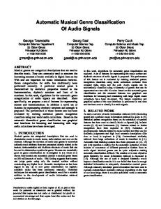
Merapi volcano, located in the central part of Java island, Indonesia, is considered to be one of the most active and dangerous volcanoes of the world. The danger of Merapi evolves from its eruptive behavior, which is mainly characterized by the frequent occurrence of pyroclastic flows and occasional vulcanian eruptions. Due to its location in the magmatic arc of the subduction zone formed by the Indo-Australian and Eurasian Plate boundary (see Fig. 2.1), Merapi’s magmatism is basaltic-andesitic, with SiO2 contents ranging from 50 - 56 wt. % (Gertisser and Keller, 1998, Andreastuti et al., 2000). In recent times, the viscous, highly crystalline lavas have formed repeatedly bulbous lava domes and thick stubby lava flows. Collapses of this viscous lava dome, which can be caused by either gravitational instability or internal excess pressure, generate violent nuées ardentes. Besides those so-called “Merapi-type nuées ardentes”, also fountain-collapse nuées ardentes occurred in historical times, reaching even farther distances and transporting much more material than the previous types of pyroclastic flows and surges. Together with huge debris flows (Lahars) during the tropical rainy season the volcanic activity is a continuous threat to the highly populated area at the volcano’s flanks and in the south of Merapi. Descriptions of historical eruptions since 1768 have been summarized by Voight et al. (2000a), while the prehistoric eruption history during the past 10,000 years from archeological and geological data have been described by Newhall et al. (2000). Merapi’s frequent eruptive activity with typical recurrence rates of one to six years (e.g. Hidayat et al., 2000) poses a high risk to the densely populated area at the volcano’s flanks. With around one million inhabitants, the city of Yogyakarta is situated just 28 km to the south of the active summit region and still belongs to the risk zone of Merapi. A major volcanic event will therefore not only affect the local neighborhood, but might even have a severe impact on the socioeconomic development of Central Java. Due to its high risk potential, Merapi is one of 15 volcanoes declared as “Decade Volcanoes”, a program proclaimed by the International Association of Volcanology and Chemistry of the Earth’s Interior (IAVCEI) within the frame of UNESCO’s International Decade of Natural Disaster Reduction (IDNDR) during the 1990’s. The main goals of this research program is to improve the understanding of volcanic processes and mechanisms, to contribute to hazard assessment and to improve prediction capabilities (Newhall et al., 1994).
5
Introduction
2000 1500 1000
5
2500
-7.
3000
height in m.a.s.l.
The aims of the IDNDR are addressed in the joint Indonesian-German cooperation project MERAPI (Mitigation, Evaluation, Risk Assessment and Prediction Improvement) (Zschau et al., 1998). Several scientific projects have been started in 1997 including petrological, geological, geochemical and geophysical long-term investigations for both gathering necessary structural information of Merapi and to establish monitoring baselines for the future. Due to the observation that volcanic and seismic activity are often closely related to each other at Merapi volcano (Ratdomopurbo, 2000, Ratdomopurbo and Poupinet, 2000, Voight et al., 2000b) the passive seismological project is considered as very important among the different monitoring experiments.
110
La
titu
de
.4
Lon
gitu
de
-7.
6
110
.5
-5˚
-10˚ 105˚
110˚
115˚
deep earthquakes (h > 200 km) medium earthquakes (70 km < h < 200 km) shallow earthquakes (h < 70 km) active volcanoes location of Merapi-Merbabu complex
FIGURE 2.1: Three-dimensional perspective view of Merapi volcano (top) from SW, no vertical exaggeration. Merapi volcano is located in Central Java (red star in detailed map view) and is one of 35 active volcanoes on Java island (red triangles). The global earthquake distribution (colored circles, global earthquake data 1991-1998 NEIC, mb>5) confines the convergent plate boundary between the indo-australian plate and the eurasian plate. The increase of hypocenter depths to the north indicates the Benioff-zone in the active subduction regime.
A new seismic network consisting of twelve seismic stations has been installed in July 1997, providing high-quality continuous digital recordings. The stations have been grouped at three different locations forming small-aperture (mini) arrays with four seismometers each (central broadband and three surrounding short-period seismometers). Together, these mini arrays act as a seis-
6
Introduction
mographic network around the summit of Mt. Merapi allowing precise localization of seismic sources by exploiting both the array and network properties of this configuration. Recording continuously at all stations, the amount of accumulated digital data lies in the order of several hundred MegaBytes per day (slightly dependent upon the dynamic range of signals which influences the effectiveness of compression algorithms). To reduce the workload of visual data analysis and to enable the detailed investigation of seismic signals of volcanic origin, there is the need for a robust automatic event detection and classification system. The design of such a system is the goal of this study. Methods for robust seismic signal detection have been under investigation since the beginning of digital seismology. Considering the enormous development in data acquisition and storage technology, it has become an issue of growing importance. Until some years ago the main aspect of signal detection was to reduce the amount of the recorded digital data to manageable levels in order to use the limited and expensive storage capacities economically. Nowadays, as digital storage has become inexpensive and common digital acquisition systems allow recording of continuous, high-resolution data streams at high sample rates, the use of detection algorithms can be seen primarily in the task to flag signal segments of continuous data streams for subsequent automatic and/or interactive analysis (Withers et al., 1998). Main purpose of available seismic signal detection algorithms is the automatic detection and timing of body phase arrivals in seismogram recordings of tectonic earthquakes and artificial explosions (chemical and nuclear). Seismic signals generated either by earthquakes or artificial explosions show a compressional body wave type at the beginning of the observed seismograms, normally characterized by sudden changes in both frequency and amplitude with reference to the preceding seismic noise. The methods used for detecting such transient signals try to exploit these characteristics by comparing short-time to long-time statistics of signal parameters and subsequent hypothesis testing. Most studies in seismic signal classification have focused on the discrimination problem between natural and artificial sources. This important task has mainly been applied in two domains, a) in the context of pruning local and regional earthquake bulletins from recordings of quarry blast explosions, and b) in the context of the verification of nuclear test ban treaties (CTBT, Hoffmann et al., 1999) within a worldwide station network. Mostly spectral ratios of certain wave groups (Pwave, S-wave, Lg-wave) have been used to accomplish this task. As a consequence, the wavegroups under consideration have to be extracted beforehand, which in turn is still a major challenge to automatic processing algorithms. Pattern recognition approaches, which aim to jointly detect and classify the complete seismogram, have rarely been used in the context of seismic signal detection and classification. Joswig (1990) developed a robust seismic event detector which is based on the comparison of spectral images (sonogram) to a set of reference templates. Recently, Gendron et al. (2000) have applied the discrete wavelet transform, combined with a wavelet based de-noising technique and a Bayesian classifier (MAP) for joint detection and classification of continuous seismogram recordings. Taking into account the special nature of volcano-seismic events, a novel method for joint detection and classification of seismic signals of volcanic origin is presented in this study. Volcanogenic quakes mostly appear to have emergent signal onsets and low signal to noise ratios. This makes it difficult to adopt detection algorithms used for onset time estimation of seismic tran-
7
Introduction
sients in earthquake studies. The usually complex wavefield characteristics of volcano-seismic signals, and - in the case of volcanic tremor - the absence of clear phase arrivals as well as the great variability in signal duration suggest the use of a classification approach, which is capable to incorporate context dependent information into the recognition process. A recognition problem of comparable complexity is found in the field of digital speech processing. Similar to volcano-seismic signals (i.e. volcanic tremor), the acoustic waveforms of speech show great variability in both utterance length and signal characteristics. The current-state-of-theart approach in speech recognition is the stochastic modeling of time-varying short time features of the acoustic observation by hidden Markov models (HMM, Rabiner and Juang, 1986, Rabiner, 1989). The hidden Markov modeling approach is capable to use the context-dependent information for the recognition process and has proven to allow recognition rates up to 90-95% depending on the specified recognition task (speaker-dependent or -independent recognition, laboratory or noisy environment conditions, isolated word or continuous speech recognition, to name a few). In speech recognition the parametrization of acoustic signals has been studied intensively in the past decades. The investigation of the physics of speech production and the human perception of speech have finally led to a mostly accepted form of acoustic signal parametrization, providing good classification results in speech recognition tasks (for an overview see e.g. Deller et al., 1993). In volcanic seismology, however, the problem of feature extraction and signal representation is still widely discussed. The source processes of seismic signals at active volcanoes and the generation of seismic energy are still only poorly understood. A signal representation which incorporates human expertise from routine observatory practice without any special assumptions about the source processes is seen as an appropriate starting point for seismic signal parametrization. Hence, the seismic wavefield, which is observed simultaneously at a network of small-aperture arrays will be described here by a limited number of seismological key parameters. Array techniques provide information about the direction, coherency and strength of seismic signal arrivals and are complemented by polarization attributes and spectral energy estimates. In the context of speech recognition the corresponding task would be called “speaker-dependent keyword-spotting in continuous speech”. Its goal is the identification of a small set of words (vocabulary) with high confidence in continuous speech, uttered by a single speaker. Transferring this to the given problem, the task could be best described as “volcano-dependent seismic eventspotting in the continuously recorded seismic wavefield by the use of hidden Markov models”. The parametrization of continuous seismological data streams and the use of HMMs for the detection and classification of the volcano-seismic signals occurring at Merapi volcano are presented in the following.
8
CHAPTER 3.
Seismic signals of volcanic origin
Volcanoes are the geologic manifestation of highly dynamic and complexly coupled physical and chemical processes in the earth’s interior. Volcanic processes occur on a broad range of time scales. The involved time constants may be as long as tens or hundreds of years (e.g. magma rise, magmatic differentiation) or as short as fractions of seconds (e.g. fragmentation). Fast volcanic processes, which take place within short time periods (~100 s to cs) may release seismic energy directly (e.g. magma/gas movements, explosions), whereas slower processes may cause seismic waves only indirectly (e.g. fracturing of volcanic edifice through stress changes caused by magma rise). Due to the complex nature of volcanic processes, a great variety of distinct seismic signals can be observed at volcanoes. However, despite of the diversity of volcanoes regarding e.g. the geological structure, size, the volatile content, or the chemical composition and physical properties of volcanic products, there is the remarkable observation, that the majority of volcanogenic seismic signals - although recorded in distinct volcanic environments - show comparable signal characteristics from one volcano to another. It is this observation that has given rise to the idea that seismic signals at active volcanoes share common source processes which are directly related to the internal driving forces of eruptive phenomena. Thus, the study of seismic sources at active volcanoes is considered to be an important tool (among other disciplines of geoscientific research) to improve the knowledge about the dynamics of active magmatic systems and the physics of their corresponding driving processes. The indirect estimation of the physical properties of such systems and their connection to the eruptive behavior of volcanoes are of key interest for the wide field of hazard mitigation (e.g. Chouet, 1996a). A prerequisite for the detailed research on seismic signal generation is the classification of the observed signals into event families. Besides the importance for evaluating seismic source models and their relation to volcanic processes, classifying seismic signals on a routine basis provides a way to quantify the activity state of a volcano. Classification schemes for individual volcanoes are indispensable for revealing correlations between special types of seismicity and the corresponding volcanic activity. Daily counts of individual seismic signal types are widely used in volcanic observatories for taking decisions whether to raise or to lower volcanic alert levels and for communicating the activity state of a volcano to local authorities and the public. Hence, the seismic monitoring of an active volcano, in combination with other monitoring techniques, is meant to
9
Seismic signals of volcanic origin
provide a description of the present status of a volcano. It may additionally provide indications for the difficult duty of eruption forecasting and to estimate the size of an eruption in progress (e.g. McNutt, 1996).
3.1. Overview of volcano-seismic signals and terminology Until now no consistent global classification scheme for volcano-seismic signals has been established (McNutt, 1996). This is mostly due to the great variety of names which have been proposed for volcano-seismic signal classes in the scientific literature. Most of the proposed terms have been chosen according to the visual appearance of seismograms or by the use of descriptive names indicating the striking characteristics of the seismograms’ signal parameters. In other cases the names of event classes were selected by relating the supposed source process to the signal under consideration. Additionally, several local terminologies, used in individual observatories, have been introduced to the scientific literature, without taking into account already existing and more general applying classification schemes, i.e. Minakami (1960, 1974), and Shimozuru (1972). The terminology introduced by Minakami (1960, 1974) is the most widely referenced volcanoseismic signal classification. In his work from 1960, Minakami mainly investigated the hypocenter depth distribution, the magnitude-frequency distribution, and the first motions of volcanoseismic events recorded at several Japanese volcanoes. On this basis he distinguished four groups of seismic event types: A-type, B-type, explosion quakes and volcanic tremor. A-type: This event type shows clear P- and S-wave arrivals with dominant frequencies between 5 Hz to 15 Hz. Higher frequencies, which are likely to be produced in the seismic source are probably not recorded due to instrumental limitations (limit of passband in common seismographtelemetry systems) and high local attenuation effects (McNutt, 1996). In other nomenclatures (e.g. McNutt, 1996) the typical spectral range for A-type events motivated to choose the term high-frequency event for this family of volcanic earthquakes. The hypocenter depth range for Atype events as given by Minakami (1960) is 1-10 km. The widely accepted source model for A-type events is shear failure or slip on pre-existing faults within or below the volcanic edifice. The source mechanisms derived for A-type events show a high double-couple portion, and therefore A-type events have also been termed “volcano-tectonic events” (e.g. Power et al., 1994). In contrast to “normal” tectonic earthquakes, their volcanic counterparts occur typically in swarms, rather than in mainshock-aftershock sequences (McNutt, 1996). A-type events have been related to the process of local stress-changes inside the volcanic edifice, caused by injection (or withdrawal) of magma. The tectonic release of the accumulated strain along fracture systems as seismic energy leads to A-type events. B-type: B-type events have been reported to occur mostly in a swarm-type activity showing little variation between the individual recorded waveforms (e.g. Minakami, 1960, McNutt, 1986, Power et al., 1994, Chouet et al., 1994, Miller et al., 1998). Most characteristic are the emergent, low-energetic signal onsets, monochromatic oscillating waveforms and the lack of clear S-wave arrivals. Spectral analysis showed, that the seismic energy is mainly concentrated in narrow frequency bands in the range between 1 Hz to 5 Hz. Hence, the terms low-frequency (LF) or longperiod (LP) event have been used as synonymous expressions for B-type events in other classification schemes (McNutt, 1996, Power et al., 1994). The typical hypocenter depth for B-type
10
Overview of volcano-seismic signals and terminology
Seismic signals of volcanic origin
events after Minakami (1960) is very shallow (less than 1 km), which has lead to the conclusion (e.g. Minakami, 1960), that the observed spectral properties and the lack of clear S-wave arrivals are due to the propagation of the seismic wavefield in the heterogeneous, unconsolidated, and strongly attenuating shallow layers of the volcanic edifice. In few occasions deeper source locations of low-frequency events have been reported for Kilauea volcano (Aki and Koyanagi, 1981, Shaw and Chouet, 1991). This fact and the similarity of spectral composition recorded at a large number of stations gave reason for the assumption, that not path, but source effects are mainly responsible for the characteristics of low-frequency events. However, the physical source process of low-frequency events is still under discussion. It has been observed very early, that B-type events and volcanic tremor (see below) share common characteristics, i.e. they possess similar spectral content and the observed waveforms often show a harmonic oscillating nature. Most authors agree that a non-destructive source process is responsible for both the repeated swarm-like pattern of B-type events as well as for the occurrence of volcanic tremor signals. Together with the observation, that B-type events and tremor occur in phases of increased volcanic activity, a connection to mass transport processes in the volcanic feeding system is considered as most probable cause for both low-frequency events and volcanic tremor. Volcanic Tremor: Volcanic tremor is the collective name of continuous (sustained) signals recorded at active volcanoes. Tremors mostly show no clear phase arrivals and have strongly varying signal durations, lasting from several tens of seconds to hours, days or even longer. The signals are characterized by peaky amplitude spectra mainly in the frequency range from 1 Hz to 5 Hz, although examples with higher frequency contents (> 5 Hz) have been observed. Distributions of the main frequency content and the durations for volcanic tremor signals recorded at over 100 volcanoes worldwide have been reviewed by McNutt (1992). Many studies have been conducted to reveal the source process of volcanic tremor. As has been mentioned before, the similarity of frequency spectra between low-frequency events and volcanic tremor have led to the conclusion, that volcanic tremor is in fact a series of superimposed low-frequency events at intervals of few seconds (e.g. Minakami, 1974, Koyanagi et al., 1987). The oscillating nature of volcanic tremor signals (and low-frequency events), and the corresponding sharply peaked amplitude spectra have been interpreted as resonance effects directly related to the source process. Due to the observation, that the dominant frequency peaks are recorded simultaneously at different stations, major path and site effects, which would explain the peaky amplitude spectra as well, have been ruled out as possible explanation. In the work of Aki et al. (1977) shallow volcanic tremor was explained as a result of a repeatedly excited fluid-filled crack vibration. As excitation process of the crack vibration, the tensile opening of fractures in response to excess magmatic pressure was discussed. This model was motivated from hydraulic fracturing experiments, therefore the involved fluid was assumed to be single-phase. In further developments of this model by Chouet (1981, 1985, 1986), and Chouet et al. (1987), it was concluded that the fluid must be an active element in the motion of the source in order to explain the narrow-banded nature of the spectral peaks of volcanic tremor. Other models have been developed e.g. by Seidl et al. (1981) which were based on observations from Schick and Riuscetti (1973) and Riuscetti et al. (1977) at Etna volcano. Seidl et al. (1981) discussed the interaction of gas and fluid in a two phase fluid as volcanic tremor source. The overall shape of typical amplitude spectra of volcanic tremor was modeled by seismic wave radiation from magma motions following a monopole flow pattern. The sharp spectral peaks with narrow bandwidth have been attributed to resonance conditions within fluid magma filled conduits. Schick (1988) pointed out that self-sustained pressure oscillations caused by two-phase flow instabilities is in accordance to the observed stable long-term
Overview of volcano-seismic signals and terminology
11
Seismic signals of volcanic origin
characteristics of volcanic tremor. Another mechanism of self-sustained excitation of fluid flow was proposed by Julian (1994), taking into account the interaction between unsteady flow of a viscous incompressible fluid and the conduit walls. A qualitatively different explanation for the occurrence of harmonic spectra observed at Semeru volcano has been given in a work from Schlindwein et al. (1995). It was shown, that any repeated transient source process with regular repetition intervals (of a few seconds), will produce a peaky amplitude spectrum. Consequently, the single spectral peaks reflect the frequency of event repetition, rather than the individual transient source spectrum. In this model, the source spectrum of the individual transients is maintained by the overall spectral shape. Explosion quakes: This group of volcano-seismic signals is a heterogeneous class of seismic waveforms, which are recorded in connection with explosive eruptions. The observed waveforms differ depending on eruption style and size. Often an air-shock phase can be observed in the corresponding seismograms (e.g. McNutt, 1996). In most descriptions (e.g. Minakami, 1960, McNutt, 1986), the first arrival of an explosion quake shows some similarities to the waveforms of a Btype event, regarding the frequency content and the oscillating nature. This observation was used as an argument for the dominance of path effects for shallow volcanic events. Minakami’s classification scheme was derived in a comparative analysis of seismic data from several distinct volcanoes in Japan. Hence, this general nomenclature works well at most active volcanoes. In more detailed studies for individual volcanoes (e.g. Lahr et al., 1994, and Power et al., 1994 for Redoubt volcano, Alaska; Latter, 1981, Sherburn et al., 1998 for White Island, New Zealand; Miller et al., 1998 for Soufrière Hills, Montserrat), modifications have been proposed to include other types of seismic signals which have not been addressed in Minakami’s work. A mixture between Minakami’s A-type and B-type earthquakes has been repeatedly observed and the term hybrid or mixed frequency event are commonly used for this event type (e.g. McNutt, 1996). Some typical examples of vertical ground velocity recordings for the previously described event types are given in Fig. 3.1. It has to be noted, that Minakami’s work is based on the observations made with short-period seismometers (corner frequencies around 1 Hz or higher), which have been the typical instrumentation used for monitoring seismic events at active volcanoes. However, in recent years, with the development of affordable portable broadband seismograph systems, new characteristics of seismic signals at active volcanoes have been observed. Transient seismic signals with dominant periods between several seconds to several tens of seconds have been observed at several volcanoes, i.e. Stromboli (e.g. Neuberg et al., 1994, Dreier et al., 1994, Wassermann, 1997a, 1997b, Kirchdörfer, 1999), Mount Erebus (Rowe et al., 1998), Popocatépetl (Arciniega-Ceballos et al., 1999), and recently Merapi (Hidayat et al., 2000). Those signals have mostly been termed very-long period events (VLP) or even ultra-long period events (ULP).
12
Overview of volcano-seismic signals and terminology
Seismic signals of volcanic origin
a)
b)
f) g)
c)
0
10
20
30
Time [s]
d)
e)
h)
0
10
20
30
40
50
60
Time [s]
FIGURE 3.1: Typical examples of recordings of the vertical motion for volcano-seismic event types. Seismograms a)-c) have been recorded at Redoubt volcano, seismograph 8 km from vent. a) A-type VT event, hypocenter depth ca. 6.8 km, b) mixed-type or hybrid event, hypocenter depth -0.6 km (above sea level) c) B-type or low-frequency, hypocenter depth -0.4 km; d) Explosion quakes with air wave arrival recorded at Pavlov volcano, seismograph ~8.5 km from vent; e) B-type event at Pavlov volcano, same station; a)-e) taken from McNutt (1996); f) strombolian explosion recorded at Arenal volcano, seismograph ~2.2 km from vent, raw waveform g) same as f), but high-pass filtered at 5 Hz. A clear airwave arrival can be noted at around 10 s; h) harmonic tremor sequence recorded at Arenal volcano; f)-h) courtesy of W. Taylor (Observatorio de Vulcanologia de Arenal y Miravalles del Instituto Costarricense de Electricidad, OSIVAM-ICE, San José, Costa Rica).
From the above review of source models, which have been suggested for both volcanic tremor and low-frequency events, it must be concluded, that there is still no commonly accepted and generally applying physical model available. What remains is the fact, that all models propose the involvement of unsteady fluid flow and mass transport processes in the shallow part of the volcanic edifice. Most authors assume therefore a direct connection between the eruption driving forces within a volcano and the occurrence of volcanic tremor and/or low-frequency events. Hence, those seismic event types are considered to play a key role not only in the context of understanding the physics of the complex volcanic dynamics but also in the difficult task of forecasting future volcanic eruptions with seismological monitoring techniques. From several case studies of seismicity accompanying volcanic crisis, McNutt (1996) derived a generic volcanic earthquake swarm model (compare Fig. 3.2). Based on the results of his comparative study, McNutt concluded the following important points for the seismic monitoring of volcanoes: a) a knowledge about the background seismicity - several years monitoring in quiet states of the volcano - is indispensable for the evaluation of possible seismic precursors for volcanic eruptions; b) the use of three-component and broadband seismometers for improved monitoring and for later detailed analysis; and c) the necessity for flexible monitoring strategies including other geophysical long-term measures.
Overview of volcano-seismic signals and terminology
13
Seismic signals of volcanic origin
post-eruption
relative
quiescence swarm onset
Seismicity Rate
peak rate
Eruption(s)
Background
HF swarm
LF events
Tremor
Explosion earthquakes, eruption tremor
Deep HF earthquakes
Types of Seismicity
heat, regional stresses
magma pressure, transmitted stresses
magmatic heat, fluid-filled cavities
vesiculation, interaction with ground water
fragmentation. magma flow
magma withdrawal, relaxation
Dominant processes
Time FIGURE 3.2: Schematic diagram of the time history of a generic volcanic earthquake swarm model, redrawn after McNutt (1996). On top a qualitative graph of the seismicity rate during different stages of an volcanic eruption cycle is shown. On bottom the main types of volcano-seismic events observed in each stage and the supposed dominant processes are given.
3.2. Seismic signals at Merapi volcano The local terminology and classification scheme of volcano-seismic signals at Merapi dates back to the work of Shimozuru et al. (1969). In their work, Shimozuru et al. (1969) describe the observations from a short-term seismological experiment at Merapi volcano in 1968. Five distinct seismic signal classes have been observed and are summarized as shown in Table 3.1. TABLE 3.1 Classification of seismic signals at Merapi volcano after Shimozuru et al. (1969). Type
Apparent feature
(dominant) Period [s]
Remarks
1
double spindle
0.09-0.12
high frequency
2
double spindle
0.09-0.12, 0.24-0.36
high frequency is followed by low frequency
3
B-type
0.15-0.25
same as Minakami B-type class
4
many phases
0.25-0.30
related to lava dome activity,
5
elongated spindle
0.16-0.90
associated with lava avalanche
The seismic signal classification given by Shimozuru et al. (1969) is based on single station data for only a limited observation period of three months. In 1982 a permanent short-period seismic network has been installed as part of a collaboration between the Volcanological Survey of Indonesia (VSI) and the Hawaiian Volcano Observatory (USGS-HVO). The data recorded during the eruptive cycle in 1984 at this six station short period seismograph network have been the basis for deriving a new classification scheme for seismic signals at Merapi volcano. Since then, this classification is used in the VSI to describe the seismic activity of Merapi. It has been summarized in
14
Seismic signals at Merapi volcano
Seismic signals of volcanic origin
the work of Ratdomopurbo (1995) and is shown in Table 3.2. Typical waveforms of the characteristic volcano-seismic events of Merapi are displayed in Fig. 3.3 (Ratdomopurbo, 1995).
TABLE 3.2 Classification of volcano-seismic signals at Merapi volcano after Ratdomopurbo (1995)
Type
Apparent feature
dominant frequency [Hz]
Remarks
Shimozuru et al. (1969) equivalent class
Minakami equivalent class
VTA
clear P- and S-wave arrivals,
5-8
volcano-tectonic, hypocenter deeper than 2.5 km below summit.
- not recorded -
A - type
VTB
clear P-arrival, no apparent S-wave arrival
similar to VTA
volcano-tectonic, hypocenter depth less than 1.5km below summit
B - type - ? -
shallow A-type
MP multiphase
less impulsive onset than VTevents, for a given amplitude, MP events have longer durations than VT-events, rapid amplitude decay with distance from summit
3-4
related to lava dome growth
type 4 - many phases
-
LF (lowfrequency)
monochromatic low-frequency content similar at all stations, short duration and rapid spatial amplitude decay
1-2
-
B-type - ? -
B - type
LHF
combination of LF followed by VTB
observed only during the activity phase of Merapi in 1990-1992
not recorded
combination of B-type followed by Atype
Tremor
long-lasting low-frequency tremor
1-2
-
-?-
Tremor
Guguran (Rockfall)
typical durations between 60 and 180 sec.
1 - 20
associated with rock avalanches originating at the active lava dome
type 5 - assoc. with lava avalanche. type 1 and 2 double spindle.
-
Two signal types reported for Merapi volcano have no correspondence in Minakami’s classification scheme: the multiphase events (MP) and the rockfall signals (Guguran). It has been noted by Hidayat et al. (2000), that MP events are similar to hybrid events recorded during phases of dome growth, e.g. at Redoubt Volcano (Power et al., 1994) and Soufrière Hills Volcano (Miller et al., 1998). Whereas the source process of the rockfall related seismic events is known to be connected to the gravitational collapse of parts of the active lava dome, detailed source models for the domegrowth related MP events have not yet been found. Recently, Hidayat et al. (2000) have reported interesting features of MP events deduced from recordings at a temporarily deployment of broadband seismometers at Merapi’s summit region. From the observation of very-long period pulses (~ 4s) embedded in the MP events, they discussed subsurface gas pressurization and relaxation as a possible source process, similar to work of Ohminato and Ereditato (1997) and Voight et al. (1999). As an alternative, they considered episodic stick-slip movement of the magma in the conduit, assuming significant shear strength inside the highly viscous magma. A similar source model for seismic events at Unzen volcano has been suggested by Goto (1999).
Seismic signals at Merapi volcano
15
Seismic signals of volcanic origin
FIGURE 3.3: Typical waveforms of seismic signal types recorded at Merapi after Ratdomopurbo (1995). All waveforms are recorded at the short-period seismic station PUS, at ca. 1 km horizontal distance from the active lava dome.
The background level of Merapi’s seismicity in periods of low volcanic activity was given by Ratdomopurbo and Poupinet (2000) as less than eight events per month for VT-type events (both VTA and VTB), with VTB events being five times more frequent than VTA ones. MP-type and Guguran occurrence rates vary in the range of several tens to 1000 events per month, mostly dependent on the activity state of the active lava dome. Occurrence of swarms of both deeper and shallower VT-activity has been observed to precede periods of increased volcanic activity in several occasions (Ratdomopurbo, 2000, Ratdomopurbo and Poupinet, 2000, Voight et al., 2000b). It has been interpreted as the response of the volcanic edifice to the injection of new magma from deeper crustal reservoirs. A very strong correlation to the volcanic unrest has been found for the MP-type events during phases of rapid dome growth. However, sometimes phases of aseismic dome growth have been observed, although they have been less frequent. Guguran activity increases significantly during periods of dome buildup, and a close connection to the occurrence of rockfall avalanches to the gravitational instability of the active lava dome is evident. Two interesting seismicity patterns have been observed repeatedly at Merapi volcano. One is the occurrence of VTB event swarms (within days or months) with completely identical waveforms as shown in Fig. 3.4 (Ratdomopurbo, 1995, Poupinet et al., 1996, Wassermann and Ohrnberger, 2001). A set of identical waveforms has been termed multiplet and has been used to map small temporal changes of the seismic velocity structure (Poupinet et al., 1996).
16
Seismic signals at Merapi volcano
Seismic signals of volcanic origin
FIGURE 3.4: Multiplet set of nearly identical waveforms of VTB-type events after Ratdomopurbo (1995). Seismograms were recorded at station PUS (vertical component short period) between January and September 1991 prior to the eruption of 1992.
The second interesting seismicity pattern observed at Merapi is the occurrence of rhythmic MPswarms with a duration of several days to weeks. The length of the inter-event time intervals, the time between two successive MP-events, are remarkably stable on shorter time scales (within hours). However, an evolution of the swarm is occasionally observed, with slowly decreasing or increasing inter-event time intervals. In rare cases, the single MP-events merge so close together, that the resulting seismogram is visually classified as volcanic tremor. This type of seismicity pattern has been observed on analog recordings by Fadeli et al. (1991) and has been confirmed by Budi (pers. comm.) for the digital recordings in the years 1996, 1997 and 1998. The observation is similar to swarm activity known from Soufrière Hills volcano (Neuberg et al., 1998).
Seismic signals at Merapi volcano
17
Seismic signals of volcanic origin
18
Seismic signals at Merapi volcano
CHAPTER 4.
Pattern recognition for seismic signal classification
As a result of the rapid development in computer technology in the last decades, pattern recognition has undergone a development from being the “output of theoretical research in the area of statistics” (Theodoridis and Koutroumbas, 1998, p. 1) to a scientific discipline, which has gained more and more interest because of its practical importance. Nowadays, pattern recognition applications can be found in nearly all branches of applied science, with the majority concentrating on the fields of perception and man-machine communication, i.e. speech and image recognition. A short introduction to general pattern recognition principles and for the specific application of seismic signal classification is given in this chapter.
4.1. Definition of pattern recognition Theodoridis and Koutroumbas (1998) define the term pattern recognition in the introduction of their text book as: “Pattern recognition is the scientific discipline whose goal is the classification of objects into a number of categories or classes. ... We will refer to these objects using the generic term patterns. ... Pattern recognition is an integral part in most machine intelligence systems built for decision making.” Fukunaga (1990) stressed another important issue in his definition of pattern recognition: “It is felt that the decision-making processes of a human being are somewhat related to the recognition of patterns; ... The goal of pattern recognition is to clarify these complicated mechanisms of decision-making processes and to automate these functions using computers.”. Furthermore, Fukunaga (1990) is specific in the choice of methods and tools required to achieve the stated goals: “..., we must first measure the observable characteristics of the sample. ... These n measurements form a vector X ... the observation, x(i), varies ... and therefore x(i) is a random variable and X is a random vector ... Thus, pattern recognition, or decision-making in a broader sense, may be considered as a problem of estimating density functions in a high-dimensional space and dividing the space into regions of categories or classes. Because of this view, mathematical statistics forms the foundation of this subject.”
19
Pattern recognition for seismic signal classification
Thus, the integral parts of a pattern recognition system can be summarized as follows: On the basis of problem related information acquired from experiment or theory, a mathematical formulation for a decision function has to be derived in order to categorize the given information into several classes. The decision functions are obtained in a learning process by estimating density functions from a representative set of training samples. The classification results obtained via the automated algorithm should be similar to the results derived by a human expert, who is familiar with the given classification task. In the following it will be discussed in which way a pattern recognition approach can be used for the task of seismic signal classification. Some of the basic mathematical definitions which will be used in the discussion are given in the appendix A.
4.2. Detection and classification by statistical pattern recognition The term detection is normally used for a classification problem involving two classes. The goal is to find an automatic decision between parts of observations which are regarded as signal and those which are not (noise) by the use of an appropriate mathematical formulation. Detection can therefore be considered as the most simple but also the most important classification task of all. However, the imprecise formulation of what exactly is to be considered noise can turn the detection problem into a more difficult task than a classification problem involving a large number of well-defined signal classes. In seismology the non-signal (noise) parts consist mainly of different types of ambient seismic vibrations, generally termed “seismic noise”. Seismic noise is generated by both artificial (man made noise, e.g. traffic, factory noise, instrumental noise) and natural sources (e.g., microseismicity, wind, earth tides, temperature, barometric pressure). Thus, the nature of seismic noise observations has to be regarded as deterministic. Our feeling as seismologist about what is to be considered seismic noise is therefore similar to a statement given by Scales and Snieder (1998): “noise is that part of the data that we chose not to explain”. However, the definition of noise in terms of signal processing or mathematical formulation is different. Here, noise is considered to be an uncorrelated, random sequence with well defined statistical properties, which then turns out to be a problematic view considering the deterministic nature of ambient vibrations. An interesting and more extensive discussion of this problem can be found in Scales and Snieder (1998). In the context of seismic signal detection, two different points of view can be taken. A rather common approach is to ignore the characteristics of real seismic noise and treat it as a random, uncorrelated process in the detection task. The expectation is then, that seismic noise at least tends to have more properties in common with the statistical noise than any seismic signal of interest. As an alternative approach, it may sometimes be convenient to refine the ’simple’ detection task to a multi-classification problem by considering K distinct seismic event types and N different noise signals. This multi-classification problem with M = K + N classes enables a far better approximation of the characteristics of seismic noise. A main drawback, however, is the need of detailed information about the observed seismic noise characteristics for each of the N noise classes, which may be difficult to obtain in real applications. A second major problem with this
20
Detection and classification by statistical pattern recognition
Pattern recognition for seismic signal classification
approach lies in the unrealistic implicit assumption, that all possible noise realizations are known beforehand. In the next sections general aspects of pattern recognition systems will be discussed for the multiclass (M-class) problem. As each M-class problem includes the two-class problem as a special case, the terms detection and classification need not to be distinguished further in this sense.
4.3. Elements of a pattern recognition system The pattern recognition task can be divided into five main parts. The block diagram in Fig. 4.1 (modified after Theodoridis and Koutroumbas, 1998, p. 6, Figure 1.3) shows these elements of a pattern recognition system in a sequentially ordered structure.
feature generation
sensor(s)
m∈ℜ
S
x∈ℜ
feature selection
D
classifier design
y = f ( x) ∈ ℜ
d≤D
system evaluation
uλ ( y )
FIGURE 4.1: Block diagram of a pattern recognition system (modified after Theodoridis and Koutroumbas, 1998). Measurements at one or several sensors provide the observations m to be classified. In the feature generation step signal parameters are extracted and summarized in a feature vector x . The best features containing the most information regarding the classification task are selected by an appropriate transform in the feature selection step y = f ( x ). The classifier is designed by searching mathematical formulations for a set of decision functions u λ ( y ) with the goal of minimal classification error. The real classification error is obtained in the system evaluation stage. The single stages within a pattern recognition system are interrelated, here indicated by the arrows on top of the individual processing blocks.
The first block in Fig. 4.1 represents the measurement procedure. A set of patterns is recorded (observed) at several physical sensors providing the input data to be classified. In the given example, S individual physical quantities are measured and the observed data is represented by an realS valued vector m ∈ ℜ . The vector space spanned by the measurements m is called measurement S space ℜ . In the feature generation step, signal parameter estimates are calculated from the observed data. Each single estimate is called a feature. The entirety of all generated features are summarized in a D real-valued feature vector x ∈ ℜ with dimension D (i.e. the number of signal parameters estiD mated). The vector space ℜ spanned by the feature vectors x is called feature vector space or sometimes parameter space. In absence of a priori knowledge regarding the relevance of the individual features (components of feature vector) for successful classification, as much information as possible is included into the feature vector. The resulting number of reasonable feature candidates may be large, leading to a high dimensionality of the feature vector space.
Elements of a pattern recognition system
21
Pattern recognition for seismic signal classification
In order to keep the dimension of the feature vector space in tractable limits for further processing, the feature selection step evaluates the information content of the feature vector by statistical analysis of the feature vector space. The final aim of the feature selection step is to reduce the dimensionality of the feature vector space to the d ( d ≤ D ) most significant features (or feature combinations). Hence, this task can be seen as the search for an appropriate transformation funcd D tion y = f ( x ) ∈ ℜ following the constraint of maintaining the information content of x ∈ ℜ at its best. Under the assumption that the feature vectors x are the result of a random process, the transformation f ( x ) is constructed by learning statistical properties from a representative sample D D set X = { x i x i ∈ ℜ , i = 1, 2, …, M } ⊂ ℜ of feature vectors with finite size M . X is therefore called a training set. As a result of the learning procedure, single features or feature combinations with least information content regarding the classification task are discarded and a new vector is d d formed. The resulting transformed feature vector y = f ( x ) ∈ ℜ spans the vector space ℜ of dimension d ≤ D (transformed feature vector space). On basis of the transformed feature vectors y the classifier has to be constructed. For the multiclass recognition task involving K distinct classes, a classifier consists of a set of discriminant functions u λ ( y ) , λ = 1, …, K , and a subsequent decision rule. A widely used design criterion for the estimation of the classifier is based on the objective to achieve a minimum error rate in the classification system. Applying this criterion leads to the family of classifiers which are based on Bayes’ rule, i.e. maximizing the a posteriori probability for the correct class decision. The classifier is obtained by learning statistical properties from a representative training set Y of feature d d vectors in the transformed feature vector space, with Y = { y i y i ∈ ℜ , i = 1, 2, …, M } ⊂ ℜ . If the class memberships of the single feature vectors y i in Y are known, the set is called a labelled training set. The methods for acquiring the statistical properties of Y are then generally termed supervised learning methods. Unsupervised learning strategies (cluster techniques) have to be used, if the class memberships are unknown and only an unlabeled training set is available. Finally, the overall performance of the pattern recognition system has to be quantified in the system evaluation step (Fig. 4.1, rightmost block). Although a sequential structure has been chosen for the graphical representation in Fig. 4.1, the single stages forming a pattern recognition system are not independent from one another, which is indicated by the arrow connections at the top of the figure. The results obtained at each stage may make it necessary to return to one or several of the proceeding steps and rework the system again. E.g. in case that the final system performance shows too high error rates it might be necessary to extract additional features from the raw measurements, in order to provide more information for the given classification task. Alternatively a modified feature selection criteria, or even another type of classifier might improve the recognition result. The following sub-sections introduce the individual elements of a pattern recognition system in more detail. In 4.3.1. the accumulation of data, preprocessing and the representation of information for the classification process by feature vectors are discussed. As the feature generation task depends on the given classification problem, some remarks are included in subsection 4.3.1. how to adopt this stage for seismic signals. Additionally a common approach for feature selection is presented at the end of this subsection. The problem of classifier design is addressed in 4.3.2. and the principles of estimating discriminant functions from training data are introduced. The last subsection 4.3.3. presents methods for evaluating the performance of a classification system.
22
Elements of a pattern recognition system
Pattern recognition for seismic signal classification
4.3.1. Feature generation and selection The process of acquiring information from an underlying data set (measurement space), and the estimation of the inherent information content within the obtained feature space are called feature generation (sometimes feature extraction) and feature selection, respectively. Both steps are regarded as the most important part of a pattern recognition system (e.g. Schukat-Talamazzini, 1995, p. 75, Niemann, 1990, p. 9). In the feature generation step, individual signal parameters are calculated from the raw measurements, which then build the basis for the subsequent classification process. Consequently, the single features used for the data representation must contain valuable information for the discrimination of classes. In case of a good knowledge about the underlying physical processes of the data set, a possible strategy is to derive the parametrization from the theoretical background. Alternatively, if the knowledge about the data production process is poor, a parametrization can be chosen by taking into account human expertise or by mimicking human perception principles. In the present context of seismic signal classification, the measurements consist of evenly sampled, discrete time series. Those represent recordings of the ground motion at a seismograph system proportional to ground displacement, velocity or acceleration depending on the deployed instrument type. The seismogram contains information about the involved seismic source process, the propagation medium and the instrument response. Whereas the theory of seismic wave propagation is well-developed, and the instrument response is a known quantity, the location and nature of the seismic source as well as the properties of the propagation medium are generally not well constrained. It is therefore difficult to derive an appropriate parametrization solely from theoretical considerations. The experiences from over 100 years of seismological observatory practice provide a good starting point for a reasonable choice of signal parameters for the classification of seismic signals. An important issue in the visual inspection of seismograms is the fact, that an observer is trained to look at contextual information. Whereas detailed analysis of small seismogram portions provide information about short-term signal attributes, the classification of the waveform can only be performed by taking into account the variation of signal parameters over the whole duration of the signal. An example is given in Fig. 4.2: the short time windows on the left show similar signal characteristics and would be visually classified as a portion of seismic noise. However, viewing the same signal windows within a larger time scale (Fig. 4.2 on the right) reveals that one of the signals is actually part of a seismic event (MP-type signal recorded at 1.6 km distance at Merapi), whereas the other waveform sample belongs to the preceding seismic noise. Consequently, for the classification of seismic events it is important to include contextual information either in the signal representation process (feature generation step) or in the classifier approach.
Elements of a pattern recognition system
23
Pattern recognition for seismic signal classification
0
1
2 3 Time [s]
4
5
0
10
20
30
Time [s]
FIGURE 4.2: Waveform example demonstrating the importance of contextual information in seismogram interpretation. In the left column two waveform samples are shown, which would be visually classified as seismic noise. The same waveform windows are shown on the right side on a larger time scale within their temporal context. From the contextual information, the lower seismogram sample is now clearly recognized as part of a seismic transient signal (MP-type signal at Merapi volcano).
The choice of signal attributes for the purpose of detecting and classifying seismic events has been the subject of numerous scientific research in the past. A review of the most commonly used features which have been proposed in earthquake research is provided in section 4.4. At this point it is sufficient to note that a variety of signal parameters can be derived from seismogram recordings, mostly based on knowledge sources from observatory practice as well as from considerations regarding the theory of wave propagation and the corresponding seismogram structure. At first sight, any signal parameter estimated from the raw data streams can be used to parametrize the seismic data. Without a priori knowledge about the relevance of individual signal parameters for the given classification task it is difficult to give preference to particular feature estimates. Hence, in a first step, it is common practice to include as much features as possible into the feature vector. However, the number of reasonable feature candidates may be high. In order to keep the computational complexity of the following classifier design in tractable limits, the dimensionality of the feature vector space has to be restricted to some reasonable size. The feature selection step of a pattern recognition system consequently aims to select an optimal subset of the previously acquired features for the classification task. One major difficulty in the feature selection stage is to define an optimality criterion. A common approach (see e.g. discussion in Niemann, 1983, p. 108) is based intuitively on the criterion of class separability in the feature vector space, i.e. to evaluate the discriminative power of the feature vectors. A widely used method to reduce the dimensionality of the feature vector space while maintaining the discriminative power of the feature vectors relies on the usage of linear transformations. The Karhunen-Loeve (KL) expansion has shown to be suitable for deriving an appropriate transformation with the desired properties (Kittler and Young, 1973). The KL-expansion is based upon the eigenvector analysis of the sample covariance matrix built from a training set of feature vectors. The result of this analysis can be used to linearly transform the representation vectors into a new
24
Elements of a pattern recognition system
Pattern recognition for seismic signal classification
coordinate system in which the coordinate coefficients are mutually uncorrelated, and where the information of the original feature vectors is mapped onto the first few axes of the new coordinate system. It is then possible to use a new feature vector of reduced dimension, which approximates the original representation vectors in a least square sense. Consider the original feature vector x of dimension D , and let Φ be a DxD matrix formed by D D D row-vectors φ i ∈ ℜ , which build an orthonormal basis of the vector space ℜ . Then any vector x may be represented as an expansion of the form: D
x =
∑ yi φi ,
4.1
i=1 T
with coefficients y i = φ i x . Using the incomplete expansion formula: d
x' =
∑ yi φi with d ≤ D ,
4.2
i=1
for representing x by x' will lead to the mean approximation error ε d , expressed as: D
2
ε d = E [ x – x' ] = E
∑
D
2
yi φi
i = d+1
=
∑ i = d+1
D
T T φ i E [ xx ]φ i
=
∑
T
φ i Sφ i
4.3
i = d+1
Considering the feature vector x as a random variable, the expression E[ ] is the expectation or the first statistical moment of the distribution function of the underlying random process (compare appendix A.2). Furthermore, the matrix S in the rightmost term of EQ 4.3 is equivalent to the matrix of the second moments of the random distribution function (autocorrelation matrix). S D may be estimated from a set of training vectors X = { x j x j ∈ ℜ }, j = 1, …, J like: 1 S' = --J
J
∑ x jx j . T
4.4
j=1 T
T
The matrix S = E [ xx ] equals the sample covariance matrix C = E [ ( x – µ ) ( x – µ ) ] if the overall mean µ = E [ x ] of the training set is the null vector. Minimizing ε d in EQ 4.3 is achieved by solving the eigenvalue problem Sφ i = λ i φ i . The matrix of second moments S can be written as:
T
S = Φ ΛΦ = Φ
T
λ1 … 0
… … … Φ. 0 … λD
Elements of a pattern recognition system
4.5
25
Pattern recognition for seismic signal classification
As S is a symmetric positive-definite matrix (compare EQ 4.4), all eigenvalues are real and positive. Sorting the eigenvalues λ i , i = 1, …, D , in descending order and inserting EQ 4.5 into EQ 4.3 minimizes the mean expected error ε d in a least square sense: D
∑
εd =
λi .
4.6
i = d+1
As a consequence, the linear transformation: T
y = Φ x,
4.7
where Φ contains as columns the ordered set of eigenvectors φ i , i = 1, …, D results in the KL coordinate system as given in EQ 4.1. The coordinate coefficients y i are then mutually uncorrelated and it has been shown, that the components are sorted according to their degree of information about the random variable x (e.g. Kittler and Young, 1973). A reduction of dimensionality is achieved by dropping components with index higher than d ≤ D . An appropriate value of d is usually found from arguments regarding the magnitude of the corresponding eigenvalues or by trial and error. In practice, the transformation matrix is obtained from the eigenproblem solution of the sample covariance matrix C for the centralized vector z = x – µ . The de-correlation transformation in EQ 4.7 may be further modified in order to obtain a new coordinate system where the sample covariance matrix of the feature vectors y equals the unity matrix I . This is an advantageous property if the following classifier approach is based on the euclidean metric. The so-called prewhitening transformation is given by: y = Λ
–1 ⁄ 2
T
Φ x.
4.8
This transformation normalizes the individual components y i in the transformed feature vector according to their respective standard deviation, which in turn allows to use the euclidean metric d as a proper distance measure in the reduced vector space ℜ (e.g. Deller et al., 1993, p. 62). The importance of the normalization property of the transformation given by EQ 4.8 will become evident in the following subsection. 4.3.2. Classifier design, decision rule and data learning The classifier design shall be discussed following the general idea of optimal classifiers. This leads to the formulation of the Bayes’ classifier with minimal misclassification error. Hence, feature vectors, the feature vector space and class regions are studied within a probabilistic framework. In order to be consistent with previous sections, the discussion is continued without loss of d generality for random vectors y of the reduced feature vector space ℜ .
26
Elements of a pattern recognition system
Pattern recognition for seismic signal classification d
Consider the real-valued feature vectors y ∈ ℜ , which are assumed to be the result of a doubly random process. The initial process selects the κ -th class Ω κ from a set of K classes Ω = { Ω 1, Ω 2, …, Ω K } , with an a priori probability P ( Ω κ ) . The condition: K
∑ P ( Ωκ ) =
1
4.9
κ=1
must be met in order to define a stochastic experiment. Subsequently, a second, multivariate continuous stochastic process produces a feature vector y as a member of the previously selected class Ω κ according to the conditional probability density function P ( y Ω κ ) , with the normalization constraint:
∫ P ( y Ω κ ) dy =
ℜ
1.
4.10
d
The decision rule shall be formulated as a general fuzzy rule of the form δ ( Ω κ y ) , with: K
∑ δ ( Ωκ y ) =
d
1 for all y ∈ ℜ .
4.11
κ=1
This fuzzy decision rule assigns y not exactly to one class, but decides the class membership of y for class Ω κ with probability δ ( Ω κ y ) . I.e., the condition given by EQ 4.11 assures that y is assigned to some class, i.e. it is not possible, that y is not assigned at all. A cost matrix C = [ r λκ ] KxK , κ, λ = 1, …, K is defined, where the individual r λκ quantify the individual costs of erroneously assigning a vector originating from class Ω κ to class Ω λ . The probability, that a vector y is assigned to the wrong class when applying the decision rule δ can be given by: P ( Ωλ Ωκ ) =
∫ P ( y Ωκ )δ ( Ωλ y ) dy
ℜ
4.12
d
The mean cost per class is then obtained by: R ( δ Ωκ ) =
K
K
λ=1
λ=1
∑ r λκ P ( Ωλ Ωκ ) = ∑ r λκ ∫ P ( y Ωκ )δ ( Ωλ y ) dy
Elements of a pattern recognition system
ℜ
4.13
d
27
Pattern recognition for seismic signal classification
Hence, the total expected cost R ( δ ) - also termed risk - when applying the decision rule δ is then calculated as: K
R(δ) =
K
∑ P ( Ωκ ) ∑ r λκ ∫ δ ( Ωλ y )P ( y Ωκ ) dy =
κ=1
K
λ=1 K
ℜ
ℜ
4.14
d
∫ ∑ ∑ r λκ P ( Ωκ )P ( y Ωκ ) dλ
.
δ ( Ω λ y ) dy
=1 κ=1
*
The design criterion for the optimal decision rule δ is formulated as the minimization of the expected cost R ( δ ) as given in EQ 4.14: *
R ( δ ) = min ( R ( δ ) )
4.15
{δ}
Defining the test functions (or discriminant functions) u λ ( y ) as the term in square brackets of EQ 4.14: K
uλ ( y ) =
∑ r λκ P ( Ωκ )P ( y Ωκ ) , for λ
= 1, …, K ,
4.16
κ=1
then the simple decision rule: 1 if u κ ( y ) = min λ ( u λ ( y ) ) * δ ( Ωκ y ) = 0 else
4.17
satisfies EQ 4.15 (a proof is given e.g. in Niemann, 1983). It is noteworthy that EQ 4.17 enables a deterministic assignment of y to a class Ω κ , although the initial formulation has been a fuzzy rule. For the special choice of the individual costs r λκ : r κκ = 0 , and r λκ = 1 , for λ ≠ κ , it can been shown (proof e.g. in Niemann, 1983), that choosing the test functions like: P ( Ω λ )P ( y Ω λ ) P ( Ω λ )P ( y Ω λ ) u λ ( y ) = -----------------------------------------------= ------------------------------------= P ( Ωλ y ) K P( y) P ( Ω κ )P ( y Ω κ )
4.18
∑
κ=1
28
Elements of a pattern recognition system
Pattern recognition for seismic signal classification
leads to the following optimal decision rule: 1 if u κ ( y ) = max λ ( u λ ( y ) ) * δ ( Ωκ y ) = . 0 else
4.19
EQ 4.18 and EQ 4.19 describe the optimal classifier in terms of the minimal expected error rate. As the denominator in EQ 4.18 is independent of the class index λ , it is normally not evaluated in the calculation of the test function. The optimal classifier decides for a class Ω κ given the observation vector y by choosing the maximum of the a posteriori probabilities P ( Ω λ y ) with the Bayes’ rule. Therefore this classifier is also called the maximum a posteriori (MAP) classifier, or Bayes’ classifier. The MAP classifier relies on the values of the a priori probabilities P ( Ω κ ) and the conditional probability density functions P ( y Ω κ ) , κ = 1, …, K , which are usually unknown for the given classification problem. However, given the availability of a finite training set of representative fead d ture vectors Y = { y i y i ∈ ℜ , i = 1, 2, …, M } ⊂ ℜ , and with the assumption that the individual training samples from Y have been produced independently by the stochastic process under consideration, it is possible to approximate the optimal classifier on basis of this training set (labelled or unlabeled). The quality of approximation is mostly controlled by the size M of the training set Y. There are generally three basic approaches for the estimation of Bayes’ classifiers from a training set: a) statistical classifiers, b) distribution free classifiers, and c) non-parametric classifiers. The family of hidden Markov models, which will be introduced in Chapter 5., represent a special type of a context dependent statistical classifier. As hidden Markov models have been selected for the present classification task, only the statistical classifiers are introduced here. Detailed background on distribution free and non-parametric classifiers can be found e.g in the textbooks of Fukunaga (1990) or Schukat-Talamazzini (1995). For the group of statistical classifiers, it is assumed, that the unknown conditional probability density functions P ( y Ω κ ) belong to a family of parametric density functions { P ( y Θ ) Θ ∈ M Θ } . Then the class dependent parameter vectors Θ κ taken from an appropriate manifold M Θ are estimated from the given training set. The most commonly used form for a parametric density function is the multivariate gaussian density function, given by: T –1 1 1 P ( y Θ ) = P ( y µ κ, C κ ) = ℵ ( y µ κ, C κ ) = --------------------- exp – --- ( y – µ κ ) C κ ( y – µ κ ) 4.20 2 2πC κ
Superscript T denotes vector transpose, µ κ and C κ are the class dependent mean vectors and covariance matrices, respectively, which have to be estimated from the training set. Let p κ be particular estimates of the a priori densities P ( Ω κ ) . Then, by inserting EQ 4.20 into EQ 4.18, further
Elements of a pattern recognition system
29
Pattern recognition for seismic signal classification
taking the logarithm and multiplying by – 2 , the normal distribution classifier test function is derived as: T
–1
u κ ( y ) = – 2 log p κ + log 2πC κ + ( y – µ κ ) C κ ( y – µ κ ) .
4.21
The decision rule is now turned into a decision for the minimal outcome of the test function in EQ 4.21, as EQ 4.18 has been multiplied with a negative quantity. EQ 4.21 can be simplified by dropping the first two terms on the right side. The resulting classifier is called Mahalanobis classifier, as the test function equals the definition of the Mahalanobis distance (e.g. Theodoridis and Koutroumbas, 1998, p. 25): T
–1
d M = ( y – µκ ) C κ ( y – µκ ) = uκ ( y ) .
4.22
If further all classes share a common covariance matrix, i.e. C κ = C ∀κ , then the classifier is called minimum distance classifier. If even all C κ are equal to the unity matrix I , then the classifier reduces to the euclidian distance classifier. Recalling the discussion of the prewhitening transformation in section 4.3.1., it becomes evident, that the advantage of this transform lies in the simplifications gained in the classifier design. d
Let Y = { Y i, Y 2, …, Y K } be a labeled training set with Y κ = { y κi y κi ∈ ℜ , i = 1, 2, …, N κ } , κ = 1, …, K , being the K disjunct subsets of feature vectors assigned to the individual classes. Then, estimates of the a priori densities p' κ , and the parameters of the multivariate gaussian distribution µ' κ , C' κ , can be obtained in a maximum likelihood sense as: Nκ p' κ = -----------------, K
4.23
∑ Nκ
κ=1
1 µ' κ = ------Nκ
1 C' k = ------Nκ
Nκ
∑ yκi , and
4.24
i=1 Nκ
∑ ( yκi – µκ ) ( yκi – µκ )
T
.
4.25
i=1
In EQ 4.23 to EQ 4.25, N κ is the number of individual sample vectors y κi , i = 1, …, N κ which have been labeled according to the production class κ (members of Y κ ). With the class-specific parameter estimates p' κ , µ' κ , and C' κ , it is possible to construct the individual test functions u κ ( y ) for the classification problem as given in EQ 4.21. For the task of learning a classifier from an unlabeled training set, the following difficulty is encountered. Both the parameters of the parametric multivariate density function (e.g. gaussian) and the assignments of the individual feature vectors within the training set are unknown. Hence,
30
Elements of a pattern recognition system
Pattern recognition for seismic signal classification
assuming a special form of the multivariate parametric density function P ( y Θ ) just allows the statement that the set of feature vectors is distributed according to the marginal density: K
P ( y p, Θ ) =
∑ pκ P ( y Θκ ) ,
4.26
κ
where p is the vector of a priori probabilities with components p κ = P ( Ω κ ) , κ = 1, …, K . The problem of uniquely identifying the parameters p and Θ can be solved (for density function which build a basis of the functional space) in a maximum likelihood sense by an iterative procedure known as the expectation-maximization-algorithm (EM-algorithm, Dempster et al., 1977). The EM-algorithm is a widely used technique, which is especially suited to estimate parameters from an incomplete data set. In the current context the missing part of the data is the unknown class labeling information of the individual features in the training set. Using the EM-algorithm to estimate the parameters of the multivariate normal density function from an unlabeled training set of size N , leads to the following estimation formulas for a single iteration step. Given an previous (or initial) estimate of p and Θ , the a posteriori probability γ iκ = P ( Ω κ y ) is calculated by: pκ P ( yi Θκ ) γ iκ = ------------------------------------ . pλ P ( yi Θλ )
4.27
∑ λ
EQ 4.27 is called the E-step of the EM-algorithm. The new estimates of the parameter sets p and Θ are then derived in the M-step via: 1 p' κ = ---N
N
∑ γ iκ ,
4.28
i=1
1 µ' κ = -------------γ iκ
∑
N
∑ γ iκ yi , and
4.29
i=1
i
1 C' k = -------------γ iκ
∑
N
∑ γ iκ ( yi – µ'κ ) ( yi – µ'κ )
T
.
4.30
i=1
i
Hence, obtaining estimates of the class dependent parameters p' κ , µ' κ , and C' κ , the classifier can be designed as before by inserting the estimates in EQ 4.21.
Elements of a pattern recognition system
31
Pattern recognition for seismic signal classification
Remarks: The goal of a vector quantizing scheme (e.g. the LBG-algorithm, section 5.5.1.) is to obtain an optimal partitioning of the feature vector space into cluster regions via unsupervised learning. A vector quantizer can be seen as a special form of the EM-algorithm, if the class dependent covariance matrices are conditioned to hold C κ = I , and if the euclidean distance measure is used. Furthermore it is also possible to derive the parameter training algorithm for the class of hidden Markov models via the EM-algorithm. Despite of its popularity, the multivariate normal distribution density function is sometimes not a good choice for real-world classification problems. It imposes a severe limitation on the statistical properties of the underlying random process, i.e. the distribution is unimodal, elliptical-symmetric, and the density values only depend on the Mahalanobis distance (EQ 4.22), and hence decrease exponentially with d M . In order to approximate arbitrary density functions, the multivariate gaussian mixture density can be used instead as a parametric density function: Nν
P ( y Θ ) = P ( y c κ, { µ κν, C κν } ν ) =
∑ cκν ℵ ( y µκν, C κν )
4.31
ν=1
The multivariate gaussian mixture density for each class κ is then a linear combination of multivariate gaussian densities, with mixture weights c κν , and N ν modes. The condition for the mixture weights c κν is given by: Nν
∑ cκν = 1
4.32
ν=1
The higher the number of modes N ν , the better the approximation of an arbitrary density function. However, the number of parameters ( µ κν and C κν ) which have to be estimated from a given training set is such increased significantly. The problem of identifying parameters of multivariate mixture gaussian density functions is equivalent to the problem of estimating parameters of the multivariate gaussian density function from an unlabeled training set. The analogy becomes apparent, if the components p κ of the a priori probability vector p are associated with the mixture weights c κν of EQ 4.31. 4.3.3. System evaluation The objective of the system evaluation stage of a pattern recognition system is to estimate the classification error probability from a finite test set of feature vectors. The test set has to be obtained independently from the training set, which has been used for the classifier design. An estimate of the error probability P ( e )' κ for class ω κ is obtained by simply counting the number of misclassified feature vectors e κ for this class and normalizing by the number of class members Nκ : eκ P ( e )' κ = -----Nκ
32
4.33
Elements of a pattern recognition system
Pattern recognition for seismic signal classification
This procedure is called the error counting approach. It has been shown (e.g. Theodoridis and Koutroumbas, 1998) that the total error probability P ( e )' for a M -class problem - with P ( ω κ ) being the occurrence probability of class ω κ - is calculated as: M
P ( e )' =
∑ i=1
ei P ( ω κ ) ----Ni
4.34
EQ 4.34 is an unbiased, but only asymptotically consistent estimator (for N κ → ∞ ) of the true class error probability P ( e ) . Therefore for small testing sets, the estimate may not be reliable. A minimum size of the test set N min as a function of the true error probability P ( e ) has been derived from Guyon et al. (1998). N min is estimated so that the true error probability P ( e ) does not exceed the estimate of the error probability P ( e )' by more than a fraction β of P ( e ) with a guaranteed probability (confidence) 1 – a : prob { P ( e ) ≥ P ( e )' + βP ( e ) } ≤ a
4.35
For typical values of a and β ( a =0.05, β =0.2), N min approximates to: 100 N min ≈ ----------P(e)
4.36
EQ 4.36 provides therefore an approximate formula for the minimum size of a test set with 95 % confidence, that the true error probability P ( e ) does not exceed the ratio P ( e )' ⁄ ( 1 – β ) (or is: P ( e )' by 25 %). E.g. for P ( e ) =0.05, N min has to be in the order of 2000 (!). Unfortunately, the number of samples available for both testing and training is limited. Especially in the discussed application of seismic signal classification, the number of observations for a certain event type may be small (in the order of some tens or even less). Therefore the limited size of the data set has to be exploited as good as possible for both training and testing. Three common approaches for estimation of the classification error probability from a finite data set are presented: Resubstitution Method: For both training and testing the same data set is used. It was shown by Foley (1972), that this procedure provides an optimistic estimate (underestimation) of the true error probability. The amount of bias is a function of the ratio N / l , where N is the number of samples in the data set and l the dimension of the feature vectors. Both N and N / l have to be large ( N / l larger than 3) to provide a reasonable estimate of the true error probability (Theodoridis and Koutroumbas, 1998, p. 342). The resubstitution method provides a lower bound for the true Bayesian error in case of a Bayesian classifier (e.g. Fukunaga, 1990, p. 220). Holdout Method: Two subsets are built from the data set in order to obtain independent sets for training and testing. This method is seen as problematic, as no optimal rule can be given how to split the data set, i.e. how many samples of the set are used for training, and how many for testing. The classification error estimate obtained is higher than the true error probability and provides an upper bound of the Bayesian error.
Elements of a pattern recognition system
33
Pattern recognition for seismic signal classification
Leave-one-out Method: In this method the finite size of the data set is used most efficiently, yet the independency between training and test set is maintained. The training is performed on N – 1 samples of the data set, and then the excluded sample is tested. For each misclassification an error is counted. After N repetitions all samples have been tested independent of the training data. As the holdout method, the estimated classification error is an upper bound of the true bayesian error. The main drawback of the leave-one-out method is its high computational requirements, as the classifier has to be estimated N times.
4.4. Review of pattern recognition methods applied in seismology Pattern recognition techniques have a long tradition in seismology and an extended overview about this topic has been given by Joswig (1996). Most of the published work has concentrated on three domains. The detection of weak seismic signals, the problem of seismic phase identification, and the discrimination between natural earthquake signals and artificial explosion seismograms. The problem of weak local earthquake recognition and the discrimination between local earthquakes and quarry blast signals recorded either at a single or at a small network of seismic stations is an important issue in terms of seismic risk evaluation. ’Clean’ bulletins with low magnitude of completeness values are of crucial importance for the evaluation of magnitude-frequency distributions and mean return times for damaging earthquakes. On a global scale, the discrimination between tectonic earthquakes and nuclear explosion signals recorded at regional or teleseismic distances is still a major challenge in the context of nuclear test ban treaty verification (Comprehensive Nuclear-Test-Ban Treaty, CTBT, Hoffmann et al., 1999). Reliable automatic algorithms are of considerable interest within these problem domains in order to a) reduce the workload in routine observatory practice (detection and phase identification problem), to b) provide pruned earthquake bulletins on both local and global scales on an automatic basis and to contribute to the monitoring problem of nuclear underground explosions (discrimination problem). It has to be noted, that in the area of volcano seismology only few studies have been published regarding the automatic seismic signal classification within the framework of pattern recognition. Seismic signal classification in earthquake analysis has been addressed in almost all cases as a two-stage process. The task has been split into the simpler detection problem and the subsequent categorization of detected time segments into event classes. Hence, the parametrization of seismic signals on the waveform level has been discussed in the context of automatic signal detection and phase identification algorithms. The choice of classifier functions and the implementation of pattern recognition systems have been mostly addressed in studies investigating the discrimination problem. The choice of signal attributes which have been proposed in literature within the context of seismic event detection depend on the type of available input data. The summary is hence divided into three parts: signal parametrization (feature generation) for a) single station single component recordings (SSSC), b) single station three component seismograms (SS3C), and c) multi-station single/three component data (MSS/3C). (Due to the extent bibliography which can be found for this special topic, the review has been restricted to the most common approaches in the further). Features from SSSC data: Hypothesis testing is the most common approach for the detection and onset time estimation of seismic phases in single trace data. Freiberger (1963) was the first to use a likelihood ratio detection statistic based on the Neyman-Pearson criterion (see e.g. Fukunaga, 1990, p. 59) to test the presence of a transient signal in seismic noise from the short term
34
Review of pattern recognition methods applied in seismology
Pattern recognition for seismic signal classification
mean squared amplitude. Since Vanderkulk et al. (1965), a comparison of short term average to long term average signal attributes build the basis for detection statistics on a scalar variable. This type of signal detectors are commonly known as STA/LTA (short-term average to long-term average ratio) trigger algorithms and have been reviewed by Allen (1982), Joswig (1990), and recently by Withers et al. (1998). The parametrization of the seismograms comprises different filtering approaches to enhance signal to noise ratios and further short-term averaging either the squared (e.g. Swindell and Snell, 1977) or the absolute amplitude values (Vanderkulk et al., 1965). Other signal detector implementations have been based on the weighted sum between the trace amplitude and the first order derivative of the amplitude (e.g. Stewart, 1977, Allen, 1978) or on the seismic envelope (Baer and Kradolfer, 1987). Besides energy attributes, information of the frequency content of seismograms have been used for hypothesis testing as well. Anderson (1978) e.g. made use of an estimate of zero crossings and Shensha (1977) developed a detector algorithm based on a weighted sum of power spectral density coefficients. The concept of STA/LTA detector algorithms is easily extended to any kind of available data (SS3C, e.g. Withers et al., 1998). Features from SS3C data: If single station three component records are available, the polarization attributes of seismic signals have been investigated and used for seismic phase characterization. The sample covariance matrix, which is formed from the three dimensional vector of seismic motion within a short analysis window, is generally used to determine the polarization behavior of seismic signals (Flinn, 1965). The solution of the eigenvalue problem for the covariance matrix leads to the formulation of the best fitting polarization ellipsoid in a least square sense, where the eigenvectors provide information about the orientation, and the connected eigenvalues describe the form of the ellipsoid. The most widely used parameter for the detection of body-wave arrivals from three component data is a measure of the degree of linear polarization, derived from the ratio of eigenvalues (e.g. Montalbetti and Kanasewich, 1970, Jurkevics, 1988). Alternatively, measures of linear polarization are obtained on basis of regression analysis (Roberts et al., 1989, Bopp, 1992). Less frequent, the deflection angle calculated under the assumption of an compressional body-wave type (Jurkevics, 1988, Roberts et al., 1989), the magnitude of the largest eigenvalue (Magotra et al., 1987), or the simple ratio of vertical to horizontal signal power (e.g. Jurkevics, 1988), have been the basis for seismic phase detectors. Features from MSS/3C data: A detector for single component array data has been presented by Blandford (1974) and is based on a measure of coherence for a plane wave signal arrival across an array. The coherence measure used in the study of Blandford (1974) is the semblance coefficient (Neidell and Taner, 1971) calculated in the time domain. The semblance coefficient is approximately F-distributed, which allows to derive thresholds for signal detection on a theoretical basis. The signal detector after Blandford (1974) has therefore been termed F-detector. Most studies in the field of array analysis methods aimed to enhance the signal to noise ratios of seismic phases by the use of stacking techniques. Well-known examples are delay and sum beamforming techniques in both time and frequency domains or n-th-root stacks. In most cases, however, the resulting features which have been subsequently exploited for signal detection or classification purposes are enhanced energy attributes of the local seismic wavefield crossing an array of seismic stations. Further signal parameters which can be obtained from array analysis methods are the apparent velocity and the direction of wave propagation for a plane wave arrival. This information has been mainly used for characterizing seismic phases and in the context of automatic hypocenter determination efforts (e.g. Bache et al., 1993). The use of 3-component array data has been rarely addressed in literature. Jurkevics (1988), e.g., improved the stability of polarization esti-
Review of pattern recognition methods applied in seismology
35
Pattern recognition for seismic signal classification
mates for single stations by averaging the single station sample covariance matrices within an array configuration. The use of a variety of classifier functions have been proposed in literature for the discrimination and classification of seismic events. Examples can be given for linear classifiers (e.g. Shumway, 1982, 1996, Wüster, 1993, Kushnir et al., 1999), quadratic classifiers (e.g. Kushnir et al., 1999) neural network classifiers (e.g. Musil and Plesinger, 1996, Falsaperla et al., 1996, Fedorenko et al., 1999, Tarvainen, 1999), cross-correlation techniques (Joswig, 1990, Wassermann, 1997a), and Bayesian classification approaches (e.g. Kushnir, 1990, Gendron et al., 2000). The majority of classification techniques are based on a set of phase attributes, such as amplitude ratios, spectral ratios, phase slowness, and polarization attributes of individual phases. Considering the goals of seismic event detection and classification algorithms in the context of regional and teleseismic earthquake analysis, these phase related attributes are of major interest and additionally well suited for subsequent location of the observed events. However, in local earthquake analysis as well as in volcanic seismology these approaches pose a major problem, because of the difficulties to clearly identify seismic phases. Thus, techniques, which make use of the complete seismogram information without the need of a priori phase segmentation appear to be better suited for automatic classification of local seismic events. Most interesting in the context of automatic seismic signal classification on continuous data streams are those approaches which are capable to process the input data in a sliding analysis technique and are not dependent on the precise alignment of seismograms. Two approaches which match the stated requirements are the methods presented by Joswig (1990) and Gendron et al. (2000). A conceptually interesting approach, which allows joint signal detection and classification of the complete seismic waveform, was introduced by Joswig (1990). In his work, Joswig (1990) used a pattern matching approach based on a smoothed time-frequency representation of the single-trace seismogram recording, termed sonogram by the author. Introducing an additional noise adaption technique on the sonogram images and reducing the dynamic range of the spectral amplitudes to a small number of discrete values, Joswig mimicked the process of human cognition (Joswig, 1994). Detection and classification is achieved in a single step by applying a two-dimensional cross-correlation between the observed sonogram and a set of reference sonogram templates. Additional thresholding is used to reject false detections. An extension of the sonogram detector for three component seismograms has been investigated by Klumpen and Joswig (1993) for the re-evaluation of local earthquake data. Analog to the sonogram detector of Joswig (1990) the basis for the automated evaluation of seismic events are time-frequency images of seismogram attributes. Whereas in the former approach these attributes were connected to the seismic signal energy, in the work of Klumpen and Joswig (1993), polarization attributes of the three-component records are displayed as time-frequency images. In the signal processing stage, only the eigenvector connected to the largest eigenvalue is considered and a rotation into the ray-coordinate system is performed. Analog to the sonogram detector, a noise adaption technique is used. The final representation of the 3 component recording consists in a set of binary images corresponding to generic polarization pattern of P, SH, and SV portions of the seismic signal. Recently, Gendron et al. (2000) suggested the use of wavelet transform coefficients as an appropriate way to parametrize seismic signals for detection and classification purposes. Detection is achieved by hypothesis testing of the wavelet coefficients within each scale of the time-scale (frequency) plane. After detection, the positions of signal start, peak energy and signal end in the discrete wavelet transformed seismogram (time and scale, i.e. frequency band) are used for classification on basis of a trained MAP-classifier.
36
Review of pattern recognition methods applied in seismology
Pattern recognition for seismic signal classification
4.5. A novel strategy for the classification of volcano-seismic signals In this study a widely used pattern recognition approach named hidden Markov model (HMM) is adopted for the classification of seismic signals of volcanic origin. Most research on this special type of context dependent classification approach has been conducted in the field of speech recognition. The proven success of HMM-based methods in modern speech recognition applications has given rise to the popularity of hidden Markov models in other pattern recognition tasks. Since today, HMM applications have been published in many classification problems, e.g. analysis of gene sequences (e.g. Churchill, 1992, Haussler et al., 1994), classification of electrocardiograms (Thoraval et al., 1994, Koski, 1996), character recognition (Vlontzos and Kung, 1992), face identification (Samaria and Young, 1994) or sonar signal classification (Kundu et al., 1994). The use of hidden Markov models for the special problem of classifying volcano-seismic signals has been motivated in first place by the analogy between the speech recognition task and the problem of identifying transient seismic signals. In both cases, the final aim is to detect and classify transient signal parts within an one-dimensional continuous discrete time series. The individual waveforms belonging to a single signal class (e.g. utterances of a word in speech recognition) are very heterogeneous, i.e. they show great variability regarding the signal length, signal strength, spectral composition or other signal characteristics. Hidden Markov models, i.e., represent a stochastic approach which is capable to address the typically observed variabilities of speech waveforms (or equivalently volcano-seismic signal recordings). Although in principle HMMs are closely connected to dynamic time warping (DTW) approaches (e.g. Ney, 1984), they allow a more generalized representation of signal classes due to the availability of efficient training algorithms. The necessity of an extensive database of reference templates in DTW algorithms, which may be described by a single HMM, have led to the revolutionary replacement of DTW techniques by HMM-based classification approaches in speech recognition applications during the mid 1980’s (e.g. Deller et al., 1993). An example of the similarity of acoustic and seismic waveforms is shown in Fig. 4.3. Two pairs of similar waveforms are displayed. Without considering the different time scales, it is not possible to distinguish the acoustic (left) from the seismic (right) waveforms.
A novel strategy for the classification of volcano-seismic signals
37
Pattern recognition for seismic signal classification
0
10
Time [s]
0
5
Time [s]
FIGURE 4.3: Comparison of waveforms for speech (left column) and volcano-seismic signals (right column). The upper left signal show the microphone recording of the unvoiced fricative “s” in “(s)ee”, and the lower left waveform is a typical realization of the vowel “I” in “(I)t” (figures from Deller et al., 1993). On the upper right panel, a typical MP-type event recorded at Merapi volcano is displayed. The lower left waveform is a portion of starting volcanic tremor observed at Arenal volcano. All figures have arbitrary amplitude units.
Especially for seismic signals of volcanic origin this close correlation to the speech signal regarding the visual appearance is not by chance. Considering the physics of speech production and the previously discussed ideas (see 3.1.) for the generation of seismic signals at volcanoes, i.e. B-type events and volcanic tremor signals, an interesting analogy is recognized. The excitation mechanism in both cases (well-known for the speech production and supposed process for volcano-seismic signals) may be described by turbulence or instability of a fluid flow process. Resonance effects are considered to play an important role in both the modulation of the speech signal as well as the seismic signal. In speech the resonances occur within the vocal tract, whereas resonances of cracks, cavities or conduits have been discussed for volcanic tremor and or B-type volcanic events. Considering the similar characteristics of acoustic and seismic signals of volcanic origin and further taking into account the special properties of hidden Markov models with respect to their capability of representing complex temporal structures within an relatively simple stochastic model, a hidden Markov model based classification approach seems to be especially suitable for the detection and classification of volcano-seismic signals.
38
A novel strategy for the classification of volcano-seismic signals
CHAPTER 5.
Hidden Markov models
The basic ideas and characteristics of hidden Markov models have been summarized in the articles of Rabiner and Juang (1986), Rabiner (1989) and are described in detail in the textbooks by Deller et al. (1993) and Schukat-Talamazzini (1995). As this probabilistic approach for signal classification of discrete time series has - to the author’s knowledge - not yet been used in the area of seismology, the principles of hidden Markov models are introduced in quite some detail. The notation used in the following is mostly adopted from the tutorial paper of Rabiner (1989).
5.1. First-order discrete Markov processes A dynamical system shall be described at every time step t = 1, 2, …, T by the means of a state variable q t taken from a finite set Q = { S 1, S 2, …, S N } containing N distinct states S i . A discrete Markov process is then defined as a probabilistic process over Q . At each time step a transition from one state to all other states is allowed and the likelihoods of occurrence of the transitions are described by transition probabilities associated with the state. Let the actual state be denoted as q t , then the system can be fully described in a general probabilistic sense by specifying q t and all predecessor states q t – 1, q t – 2, …, q 1 the system has entered ever before, beginning at time t = 1 with state q 1 . In the special case of discrete, first-order Markov chains only the current and the last preceding state are taken into account, i.e. ! P [ q t = S j q t – 1 = S i, q t – 2 = S k , … ] = P [ q t = S j q t – 1 = S i ]
5.1
Considering the whole process as independent in absolute time (stationarity), the system can be described by the use of EQ 5.1 and the real-valued state transition probabilities a ij ∈ ℜ are defined as: a ij = P [ q t = S j q t – 1 = S i ] ,
1 ≤ i, j ≤ N .
5.2
In order to realize a stochastic experiment the state transition probabilities a ij have to obey (fulfill) the stochastic constraints:
39
Hidden Markov models
a ij ≥ 0 , and
5.3.a
N
∑ aij =
1.
5.3.b
j=1
The a ij are then summarized in the state transition probability distribution matrix A = [ a ij ] NxN of size NxN . Furthermore, the probabilities of the initial state variable q 1 at the begin of the process have to be specified. The N probabilities for q 1 being in state S i are summarized in the real-valued initial N state distribution vector π ∈ ℜ , with: πi = P ( q1 = Si ) .
5.4
The π i are required to obey (fulfill) the constraints π i ≥ 0 , and
5.5.a
N
∑ πi =
1.
5.5.b
i=1
The outcome of this stochastic experiment results in an observation sequence for a specified time length T which can be denoted as q 1, q 2, …, q t, …, q T . Rabiner (1989) called this stochastic process an ‘observable Markov model’, as at each time step the process outputs an observable event (the given state itself).
5.2. Extension to discrete hidden Markov models Consider now the same stochastic process as in 5.1.. Again there exists a finite set of states Q = { S 1, S 2, …, S N } and a probabilistic process on Q produces a sequence of state variables q t , i.e.: q = q 1, q 2, …, q t, …, q T , q t ∈ Q .
5.6
The transition probabilities a ij between states in the sequence are defined as in EQ 5.2 with properties as given in EQ 5.3.a and EQ 5.3.b. The definition of initial state probabilities π i can be recalled by EQ 5.4 and constraints as in EQ 5.5.a and EQ 5.5.b. On top of this primary process (discrete, first-order Markov chain) a second stochastic process is defined by drawing a discrete observation symbol v k taken from a finite set K = { v 1, v 2, …, v M } of length M according to a state dependent probability distribution (discrete probability density function).
40
Extension to discrete hidden Markov models
Hidden Markov models
For the observer of such a process only the discrete observation symbol sequence O of length T : O = O 1, O 2, …, O T
5.7
is visible, while the underlying state sequence q is hidden. Assuming statistically independency between successive symbols within the sequence O , i.e. the current symbol O t depends only on the current state q t , the production probability of the symbol sequence O is given by: ! P ( O t O 1 …O t – 1, q 1 …q t ) = P ( O t q t )
5.8
The state dependent symbol probability for emitting symbol ν k while being in state j shall be denoted as: b jk = b j ( v k ) = P ( O t = v k q t = S j ) .
5.9
The real-valued b jk ∈ ℜ can be summarized in the symbol probability distribution matrix B = [ b jk ] NxM of size NxM . The b jk follow the stochastic constraints: b jk ≥ 0 , and
∑ b jk
= 1
5.10.a
for 1 ≤ j ≤ N and 1 ≤ k ≤ M .
5.10.b
k
In the following the terms b jk , b j ( k ) and b j ( O t ) = b j ( O t = v k ) = b jk will be used equivalently depending if the matrix components of B are addressed or reference to a certain observation symbol at time t is made. The complete (double) stochastic process is named discrete hidden Markov model (DHMM), as the output symbols are taken from a discrete set of output symbols, and the underlying state variable sequence which is the outcome of the discrete first-order Markov process is not observable (hidden). The model is described by the number of possible states N , the number of possible output symbols M , the initial state probability distribution π , the state transition probability distribution matrix A and the symbol probability distribution matrix B . For fixed dimensions N and M , a hidden Markov model is written in short notation as: λ = ( π, A, B ) .
5.11
After outlining the formalism for discrete hidden Markov models, the use of this stochastic model for classification shall be discussed. This leads to the formulation of the three problems for hidden Markov models (e.g. Rabiner and Juang, 1986).
5.3. The three problems for hidden Markov models As seen in the previous section 5.2., a hidden Markov model can be considered as a parametrization of a doubly embedded stochastic process which produces a time sequence of observations as
The three problems for hidden Markov models
41
Hidden Markov models
output. The usage of HMMs for classification will become obvious if answers to the following problems (Rabiner, 1989) can be given: a) Evaluation problem: A stochastic experiment has produced the observation sequence O = O 1, O 2, …, O T and a hidden Markov model λ = ( π, A, B ) is given. The evaluation problem raises the question of how to compute the conditional probability P ( O λ ) , that the observation sequence has been produced by the model λ ? Alternatively, the question can be put this way: given a model λ and the observation sequence O , how is the model judged? If several competing models are available, the solution to this problem leads directly to the classification problem. The probability measure P ( O λ ) will then provide a measure for choosing the model which best matches the observation. b) Problem of optimal state sequence: The sequence O = O 1, O 2, …, O T was observed and a hidden Markov model λ = ( π, A, B ) is given. The problem of optimal state sequence deals with the question of how to specify the most probable underlying state sequence that has produced the observation O . I.e., how to estimate that state sequence I = i 1, i 2, …, i T out of all possible state sequences q = q 1, q 2, …, q T , which is optimal in some meaningful sense? The answer to this question allows to uncover the hidden part of the model. Furthermore an alternative approach for the evaluation problem (5.3.1.) is derived when trying to address the problem of the optimal state sequence. c) Training problem: Given the model parameters of λ = ( π, A, B ) and some observation O = O 1, O 2, …, O T , the training problem poses the question of how to adjust the model parameters A , B , and π in order to maximize the probability measure P ( O λ ) ? Obviously, the solution to this problem will provide a method to train models λ out of a set of time sequences observed in some experiment. As will be shown later, the training problem can be solved very efficiently and is considered as one of the major advantages of hidden Markov models in comparison to other approaches in pattern recognition problems. 5.3.1. Solution to the evaluation problem Following the argumentation in Deller et al. (1993, p. 686), the “most natural measure of likelihood” for a given λ and some observation O would be the conditional probability P ( λ O ) providing a measure of how good the data can explain the model. However, the available training data does not allow to compute this quantity. Instead, what is usually observed is the probability that a given model λ will generate certain output sequences O , rather than the converse. Thus the conditional probability P ( O λ ) can be specified from the data set, but not P ( λ O ) . Recalling that the conditional probabilities P ( O λ ) and P ( λ O ) can be written as:
42
P ( O, λ ) P ( O λ ) = ------------------- , and P(λ)
5.12
P ( O, λ ) P ( λ O ) = ------------------- , P(O)
5.13
The three problems for hidden Markov models
Hidden Markov models
where the term P ( O, λ ) denotes the joint probability of O and λ occurring together. Then, by combining EQ 5.12 and EQ 5.13, the formulation of Bayes rule is obtained: P ( O λ )P ( λ ) P ( λ O ) = ------------------------------- . P(O)
5.14
It is evident, that choosing a model λ , which maximizes the left side in EQ 5.14, will also maximize the right side of EQ 5.14. The normalization term P ( O ) denotes the probability, that the observation sequence O is observed in the experiment. As it is independent of the model λ , it is usually not used for the calculation of P ( λ O ) (see also EQ 4.18 in 4.3.2. for the Bayes’ classifier). If the a priori probabilities P ( λ ) are assumed to be equal for all models λ , than the conditional probability P ( O λ ) serves equally well as an evaluation measure for P ( λ O ) . The term P ( O λ ) is often called maximum likelihood probability. The task of hidden Markov model evaluation is then equivalent to finding an expression for calculating the probability P ( O λ ) from a given observation sequence O = O 1, O 2, …, O T and a given model λ = ( π, A, B ) . The probability of every possible state sequence I of length T can be evaluated in a straight-forward way. Given a (fixed) state sequence I = i 1, i 2, …, i T , being a single and valid realization of q , the conditional probability P ( O I , λ ) is a formulation of the probability that O has been produced by model λ following the state sequence I . This probability can be expressed intuitively by the state dependent symbol output probabilities b i ( O t ) as: P ( O I , λ ) = b i ( O 1 )b i ( O 2 )…b i ( O T ) 1
2
5.15
T
The probability of a single state sequence I = i 1, i 2, …, i T can be computed using the characteristics of the underlying discrete Markov process as: P ( I λ ) = π i a i i a i i …a i 1
1 2
2 3
T – 1 iT
.
5.16
The joint probability of O and I given λ , or in other words the probability that O and I occur simultaneously given the model λ , is calculated as the product of EQ 5.15 and EQ 5.16, i.e.: P ( O, I λ ) = P ( O I , λ )P ( I λ )
5.17
Then the desired probability P ( O λ ) is obtained by summing the joint probabilities P ( O, I λ ) over all possible state sequences: P(O λ) = =
∑
i 1, i 2, …, i T
∑ P ( O, I λ ) = ∑ P ( O I , λ )P ( I λ )
all I
all I
π i b i ( O 1 )a i i b i ( O 2 )…a i 1
5.18
1
1 2
2
T – 1 iT
bi ( OT ) T
EQ 5.18 is then interpreted as follows: at the begin of the process the system starts in state i 1 with probability π i . The first symbol O 1 is generated with probability b i ( O 1 ) . Then a transition is 1 1 made from state i 1 to state i 2 with probability a i i . Now the symbol O 2 is emitted with proba1 2 bility b i ( O 2 ) . State transition and symbol generation is then continued until the final transition 2 from state i T – 1 to state i T with probability a i i . The last symbol O T in the sequence is genT –1 T
The three problems for hidden Markov models
43
Hidden Markov models
erated with probability b i ( O T ) . The summation over all possible state sequences results in the T probability P ( O λ ) . It is evident why this approach is sometimes called “any path” method (Deller et al., 1993). T
T
In this direct computation a total number of ( 2T – 1 )N multiplications and N – 1 additions are necessary to evaluate P ( O λ ) (Rabiner, 1989). Even for small model sizes N and short observation lengths T the number of calculations involved becomes intractable. Fortunately, an efficient method is known for calculating P ( O λ ) which is called forward-backward algorithm and was introduced in the work of Baum and Eagon (1967) and Baum and Sell (1968). The cost of computations can be reduced dramatically by defining the variable α t ( i ) (often referred to as forward variable): α t ( i ) = P ( O 1 O 2 …O t, i t = S i λ ) .
5.19
EQ 5.19 can be interpreted as the probability of the partial observation sequence beginning at time t = 1 and ending in state S i = i t at time instant t given the model λ . The computation of α t ( i ) is achieved inductively by: Initialization step: α 1 ( i ) = π i b i ( O 1 ) ,
1≤i≤N
5.20.a
N
Induction:
∑ αt ( i )aij
αt + 1 ( j ) =
b j ( O t + 1 ),
5.20.b
i=1
1 ≤ j ≤ N,
1≤t≤T –1
N
Termination:
P(O λ) =
∑ αT ( i )
5.20.c
i=1
In a similar way the backward variable β t ( i ) which describes the probability of the partial observation sequence beginning at time t + 1 to the end, given state S i = i t at time instant t and the model λ , is defined as: β t ( i ) = P ( O t + 1 O t + 2 …O T i t = S i, λ ) .
5.21
The induction scheme is then: Initialization step: β T ( i ) = 1 ,
44
1≤i≤N
5.22.a
The three problems for hidden Markov models
Hidden Markov models
N
Induction:
βt ( i ) =
∑ aij b j ( Ot + 1 )βt + 1 ( j ),
5.22.b
j=1
1 ≤ i ≤ N,
T –1≥t≥1
N
Termination:
P(O λ) =
∑ π j b j ( O1 )β1 ( j )
5.22.c
j=1
Please note, that for the evaluation problem either the forward variable α t ( i ) or the backward variable β t ( i ) (EQ 5.20.c and EQ 5.22.c, respectively) can be used. For the training problem, however, which is closely connected to the evaluation of P ( O λ ) , both variables are necessary as is shown in section 5.3.3.. The cost of computations can be reduced to N ( N + 1 ) ( T – 1 ) + N multiplications and N ( N – 1 ) ( T – 1 ) additions (Rabiner, 1989). 5.3.2. Solution to the problem of the optimal state sequence The solution to the problem of finding an optimal state sequence leads to a technique which is often used for both the evaluation (section 5.3.1.) and training problem (section 5.3.3.), the socalled Viterbi algorithm (Viterbi, 1967, Forney, 1973). As was stated by Rabiner (1989) the difficulty in finding a solution to the given problem lies in the definition of “optimal state sequence”. Several criteria for optimality can be given, but here only the following criterion is considered. The optimal state sequence shall be determined by choosing those states i t that appear to be individually most likely. This criterion will maximize the expected number of correct individual states. Taking a deterministic point of view and postulating that the observation sequence O has been T produced by exactly one of all possible state sequences I ∈ Q of length T , then all those state sequences I , which maximize the observation dependent a posteriori probability: P ( O, I λ ) P ( I O, λ ) = ------------------------ , P(O λ)
5.23
have to be considered as a solution to the problem. As P ( O λ ) is independent of the state * sequence I , the search for the best (optimal) single state sequence I can be obtained by: *
*
P ( O, I λ ) = max T P ( O, I λ ) = : P ( O λ ) I∈Q
5.24
*
The quantity P ( O λ ) is then a modified probability measure, which differs from the production probability P ( O λ ) presented in section 5.3.1.. Nevertheless it was shown that P ( O λ ) and * P ( O λ ) are strongly correlated (Merhav and Ephraim, 1991) and in practice this modified probability measure is often used in hidden Markov model applications (e.g. speech recognition sys-
The three problems for hidden Markov models
45
Hidden Markov models *
tems, Schukat-Talamazzini, 1995, Picone, 1990). In general several sequences I which meet EQ 5.24 may exist. The Viterbi-Algorithm gives an efficient implementation for solving the optimality problem. Instead of the forward variable α t ( i ) (EQ 5.19), now the quantities to compute are the maximal probabilities ϑ t ( i ) for generating the partial observation sequence O = O 1, O 2, …, O t ending at time t and being in state i t = S i , given the model λ : T ϑ t ( i ) = max P ( O 1 …O t, i 1 …i t λ ) I ∈ Q with i t = S i
5.25
Similar to the principles of dynamic programming (e.g. DTW Dynamic Time Warping algorithms), the ϑ t ( i ) are computed recursively, keeping track of the best path by the matrix Ψ t ( i ) . After termination, the single best path (optimal state sequence or most likely single state sequence) is determined by backtracking. In detail the algorithm can be written: Initialization: ϑ 1 ( j ) = π j b j ( O 1 ) , and
5.26.a
Ψ 1 ( j ) = 0 , for all j = 1, …, N
5.26.b
Recursion: ϑ t + 1 ( j ) = max ( ϑ t ( i )a ij )b j ( O t + 1 ) , and
5.27.a
Ψ t + 1 ( j ) = arg max ( ϑ t ( i )a ij ) , for all j = 1, …, N
5.27.b
i
i
Termination: *
P ( O λ ) = max ϑ T ( j ) , and
5.28.a
j
i
* T
= arg max ϑ T ( j )
5.28.b
j
For t = T – 1, …, 1 , the optimal single state sequence is derived by backtracking: *
*
i t = Ψt + 1 ( i t + 1 )
5.29
The solution to the problem of optimal state sequence is therefore given by EQ 5.29. At the same time a modified probability measure for the evaluation problem of section 5.3.1. is given by EQ 5.28.a. In practice, the Viterbi algorithm is often preferred for the evaluation problem as it requires slightly less computations than the number of calculations involved by the forward (or backward) variable. Another advantage is found in the practical implementation of the Viterbi46
The three problems for hidden Markov models
Hidden Markov models
algorithm. It is connected to the critical point of adequately addressing the high dynamic range required for the calculation of the probability measures. The point of adequate scaling is addressed in more detail in appendix B. There it will be shown that by the use of the Viterbi algorithm the problem of scaling can be solved more efficient when compared to the forward-backward algorithm. 5.3.3. Solution of the training problem To give an answer to the training problem, a proper estimate of the statistical parameters ( π , A , and B ) of a discrete observation hidden Markov model λ ( π, A, B ) has to be obtained from a given training sequence. As before, the ‘dimensions’ of the hidden Markov model are given by the number N of states and the number M of discrete observation symbols. Furthermore one single observation O of length T is available as training sequence. The given problem is solved by maximizing the likelihood objective function (e.g. SchukatTalamazzini, 1995), formulated as: L HMM ( λ ) = log P ( O λ ) = log
∑
I∈Q
P ( O, I λ )
5.30
T
Unfortunately, no closed form for maximizing EQ 5.30 analytically is known. Considering the convex manifold M λ : M λ = ( π, A, B ) π i, a ij, b jk ≥ 0, and
∑ πi = ∑ aij = ∑ b jk = 1 i
j
5.31
k
it can be shown that maximizing EQ 5.30 is equal to a nonlinear optimization problem with linear constraints. The iterative re-estimation formulas known as Baum-Welch algorithm have been introduced by Baum and Petrie (1966) and Baum and Eagon (1967). The algorithm is also often called forward-backward algorithm as the previously defined forward and backward variables α t ( i ) and β t ( i ) (EQ 5.19 and EQ 5.21) are used for estimating the model parameters. In the following the Baum-Welch re-estimation formulas are presented for a given start model λ 0 and a single training observation sequence O of length T . Define the a posteriori probability of a transition from state S i to state S j at time t as: P ( i t = S i, i t + 1 = S j, O λ ) ξ t ( i, j ) = P ( i t = S i, i t + 1 = S j O, λ ) = -------------------------------------------------------------- , P(O λ)
5.32
1≤t≤T
The three problems for hidden Markov models
47
Hidden Markov models
ξ t ( i, j ) is then equivalent to the expected number of transitions from state S i to state S j at time instant t within the observation sequence O given the initial model λ 0 . By the use of forward and backward variables α t ( i ) and β t ( i ) , EQ 5.32 is expressed as: α t ( i )a ij b j ( O t + 1 )β t + 1 ( j ) α t ( i )a ij b j ( O t + 1 )β t + 1 ( j ) ξ t ( i, j ) = ------------------------------------------------------------- = ------------------------------------------------------------N P(O λ) α t ( i )β t ( i )
5.33
∑
i=1
The α t ( i ) and β t ( i ) are calculated following EQ 5.20.a - EQ 5.20.c and EQ 5.22.a - EQ 5.22.c for the initial model λ 0 and the given training sequence O . Further the quantity γ t ( i ) is defined as: γ t ( i ) = P ( i t = S i O, λ )
5.34
which is equivalent to the a posteriori probability of the system being in state S i at time instant t , given the initial model λ 0 and the observation sequence O . The following equality is true for 1 ≤ t ≤ T – 1 : N
γ t(i) =
∑ ξ ( i, j ) .
5.35
j=1
Inserting EQ 5.33 into EQ 5.35 and further simplification by using EQ 5.22.b, γ t ( i ) is obtained as: α t ( i )β t ( i ) α t ( i )a ij b j ( O t + 1 )β t + 1 ( j ) γ t(i) = = -------------------------------- ------------------------------------------------------------ N N j = 1 α t ( i )β t ( i ) α t ( i )β t ( i ) i=1 i=1 N
∑
∑
5.36
∑
The Baum-Welch re-estimation formulas for the improved model parameters of λ 1 , denoted as π˜ i , a˜ ij and b˜ i ( k ) are then calculated as follows. The re-estimated initial state probabilities π' i (given the model λ 0 and the training sequence O ) are given by: π' i = γ 1 ( i ) ,
(1 ≤ i ≤ N )
5.37
If expressed in words, EQ 5.37 translates to the expected number of transitions from state S i in the first time step t = 1 .
48
The three problems for hidden Markov models
Hidden Markov models
The transition probabilities a' ij can be estimated by: T –1
∑ ξ t ( i, j )
T –1
∑ αt ( i )aij b j ( Ot + 1 )βt + 1 ( j )
t=1 t=1 a' ij = -------------------------- = -----------------------------------------------------------------------, T –1 T –1
∑ γ t(i)
∑ αt ( i )βt ( i )
t=1
t=1
5.38
which is equal to the expected number of transitions from state S i to state S j divided by the expected number of transitions from S i to any state. Put in other words, this is the expected frequency of occurrence of state transition a' ij (given the model λ 0 and the observation sequence O ). Finally for the improved observation output probabilities b' i ( k ) , the following estimation formula is used: T
∑ γ t ( i )χ [ Ot = k ]
T
∑ αt ( i )βt ( i )χ [ Ot = k ]
=1 =1 = t---------------------------------------------------------b' i ( k ) = t--------------------------------------------T T
∑ γ t(i)
∑ αt ( i )βt ( i )
t=1
t=1
5.39
Herein χ [ … ] denotes a characteristic function which evaluates to 1 in case that the expression within brackets is true, otherwise χ [ … ] = 0 . Then EQ 5.39 can be translated to the expected frequency of occurrence of symbol k while the system is in state S i (given the model λ 0 and the training sequence O ). It has been shown (Baum and Sell, 1968), that the given re-estimation formulas lead to an improvement of the model parameters in the sense that a growth of the ML-objective function L HMM ( λ ) (EQ 5.30) is always true: L HMM ( λ 1 ( π˜ , A˜ , B˜ ) ) ≥ L HMM ( λ 0 ( π, A, B ) )
5.40
A convergence of L HMM ( λ ) to a local maximum can therefore be guaranteed. If a global maximum is to be obtained in the iterative process, depends on the initial start model λ 0 . For practical implementation the following scheme is suggested (Deller, et al., 1993): Initialization: Choose an arbitrary seed model λ 0 Recursion, for l = 0, 1, … do: A) Use λ l and O to compute EQ 5.33 and EQ 5.35. B) Update the new model parameters for λ l + 1 according to EQ 5.37 - EQ 5.39.
The three problems for hidden Markov models
49
Hidden Markov models
C) It will be true that P ( O λ l + 1 ) ≥ P ( O λ l ) . If P ( O λ l + 1 ) – P ( O λ l ) ≥ ε , return to 1.) else STOP. Repeat the procedure A)-C) with different seed models to find a favorable maximum of P(O λ) .
Alternatively to the Baum-Welch (or forward-backward) algorithm presented above, it is also pos* sible to make use of the modified Viterbi measure P ( O λ ) as defined in EQ 5.24 for the re-estimation of model parameters. The so-called Viterbi training is implemented as follows (e.g. Schukat-Talamazzini, 1995): Initialization: Choose an arbitrary seed model λ 0 = ( π i, a ij, b jk ) . Recursion, for l = 0, 1, … do: *
A) Estimate the optimal state sequence I as: *
P ( O, I λ l ) = max { P ( O, I λ l ) } I∈Q
T
using the Viterbi algorithm outlined in section 5.3.2. (EQ 5.26.a - EQ 5.29). B) Calculate the expected number of initial, transition and output probabilities π i , a ij and b j ( k ) by: πi = χ [ i1 = Si ] ,
5.41.a
T –1
a ij =
∑ χ [ i t = Si, i t + 1 = S j ] , and *
*
5.41.b
t=1 T –1
∑ χ [ i t = S j, O t = v k ] . *
b j ( vk ) =
5.41.c
t=1
C) Normalize the quantities π i , a ij , and b j ( v k ) and update the model parameters π' i , a' ij and b' j ( k ) by: N
π' i = π i /
∑ πi ,
5.42.a
i=1 N
a' ij = a ij /
∑ aij , and
5.42.b
j=1
50
The three problems for hidden Markov models
Hidden Markov models
M
b' j ( v k ) = b j ( v k )/
∑ b j ( vk ) .
5.42.c
k=1 *
*
D) Set λ l + 1 = ( π' i, a' ij, b' jk ) . It will be true that P ( O λ l + 1 ) ≥ P ( O λ l ) . * * If P ( O λ l + 1 ) – P ( O λ l ) ≥ ε , return to i) else STOP. Repeat the procedure A)-D) with different seed models to find a favorable maximum of * P (O λ) .
The presented approaches for the training of discrete hidden Markov models have been discussed for the case, that a single training sequence is available. An extension to multiple training sequences is straight-forward and is not presented here (see e.g. Deller et al., 1993, pp. 718-720). The training methods are based on the maximum likelihood approach. It is important to note, that the ML-training approach does not include any means of “negative training”. The model parameters are adjusted in the training process to maximize the probability P ( O λ ) of generating the observation for which it is “responsible”. Therefore, the model is trained to respond favorably to its own class, but it is not improved with respect to discriminate against observation sequences produced from a competing model. Strategies, which have been developed especially for providing good discrimination properties of the trained models, are the so-called minimum discrimination information (MDI) approach (Ephraim et al., 1989) and the maximum average mutual information approach (MMI, e.g. Bahl et al., 1986). As those methods have not been used in the presented classification system, they are not further discussed at this point. Practical issues regarding sections 5.3.1. - 5.3.3. will be discussed in section 5.5..
5.4. The use of hidden Markov models in classification problems Knowing the solutions to the three basic problems of hidden markov models, the application of hidden markov models to the problem of classification is straightforward. As discussed previously in 4.3.2. for a classification system, it is necessary to design a classifier which is composed of a set of discriminant functions on the input data (generally a feature vector, here: discrete observation sequence) together with an appropriate decision rule. In most cases the decision rule will be a maximum or minimum decision on the outcome of the discriminant function. The solution to the evaluation problem provides now the conditional probability measure P ( O λ ) , giving the probability, that a discrete symbol sequence (input data) has been produced by a given discrete hidden Markov model. Recalling the derivation of the optimal classifier in section 4.3.2. and replacing the discrete classes Ω κ (i.e. random processes) by a set of hidden Markov model λ κ in EQ 4.18, it is evident, that P ( O λ ) already can be chosen as the discriminant function in case of equal a priori probabilities of model occurrence P ( λ ) . Hence, for distinguishing K classes, K distinct hidden Markov models λ κ , with κ = 1, …, K have to be provided to test the observed symbol sequence O = O 1, …, O T under consideration against all K models. The model providing the highest probability score is chosen as classification result. Furthermore, the solution to the training problem for hidden Markov models provides a tool to design a classifier by means of supervised learning. Herein, a training set of symbol sequences for a single class κ is selected to learn the parameters of the hidden Markov model λ κ representing The use of hidden Markov models in classification problems
51
Hidden Markov models
the class κ . Figure 5.1 summarizes the use of hidden Markov models in a simple classification problem.
discrete symbol observation sequences
training sets
Parameter Parameter Parameter Estimation Parameter Estimation Parameter Estimation Parameter Baum-Welch or Estimation Estimation Baum-Welch or Baum-Welch or Estimation Viterbi training Baum-Welch or Baum-Welch or Viterbitraining training Viterbi Baum-Welch or Viterbi training Viterbi training Viterbi training
Markov Models λ1, λ2, ..., λK
Probability Probability Probability Measure Probability Measure Probability Measure Probability Measure (OO| |λλi) ) Measure PP (O Measure (O PP (O | |λλi)i) P ( P ( O | |λλi i)i) Maximum
FIGURE 5.1: Simple classification approach using hidden Markov models. In a first phase, L training sets are selected from the discrete symbol observation sequences. K distinct hidden Markov models are trained using the Baum-Welch or Viterbi training approach. For the recognition task, the discrete symbol sequences are tested against the K hidden Markov models. The model with highest probability is selected as classification result.
5.5. Practical considerations for the design of a hidden Markov model classification system The introduction on discrete hidden Markov models is now completed with some considerations and remarks about the practical implementation of hidden Markov models. First, a method will be introduced, which allows to produce discrete symbol sequences from a sequence of real-valued feature vectors. The subsequent chapters provide information on the choice of model topologies and model dimension, strategies for initializing seed models for the supervised training procedure, and the necessary scaling of probabilities in the evaluation procedure to prevent underflow during computation. 5.5.1. Production of discrete observation sequences by vector quantization Until now it has been ignored that the input for a discrete hidden Markov model has to be a discrete observation sequence, both for training and evaluating. Hence, a method must be specified, which allows to construct a discrete symbol sequence from the sequence of real-valued feature D vectors x ∈ ℜ . This task can be accomplished by the use of a well established technique originally developed in the area of signal compression and which is known as vector quantization. D
A vector quantizer is a mapping function q from the D -dimensional real-valued vector space ℜ D into a finite set C = { c 1, c 2, …, c K } of prototype vectors c i ∈ ℜ . C is called the codebook of
52
Practical considerations for the design of a hidden Markov model classification system
Hidden Markov models
the vector quantizer. Each vector x ∈ ℜ the codebook C by:
D
is then assigned to one of the prototype vectors from
ℜ D → C = { c , c , …, c } 1 2 K . q = x → q( x)
5.43
The operator q is called a partition of the vector space ℜ D
ℜ = Y1
…∪ Y K ∪ + +
D
into K disjunct cells Y k :
Y k = { x q( x) = ck} .
,
5.44
Hence, the production of a discrete valued symbol from a real-valued feature vector is obtained by the mapping function of an appropriately designed vector quantizer, when assigning the feature vector to the index of its prototype vector from the codebook. However, information about the exact position of the feature vector in the feature vector space is lost in the quantization process. Therefore, the aim of the quantization process is to approximate the vectors x by its representative prototype vector x = q ( x ) with minimal quantization error (distortion). In order to evaluate the expected distortion of a vector quantizer, an appropriate distance function d ( x i, x j ) (metric) D has to be defined on ℜ . D
Let the distribution of vectors x in ℜ be given by the continuous density function P ( x ) . The expected distortion ε , which is subject to minimization is then written as: K
ε = E [ d ( X, q ( X ) ) ] =
∑ ∫
κ=1
x ∈ Yκ
d( x, c κ )P ( x ) .
5.45
No closed solution for the optimal vector quantizer can be given. However, two necessary conditions for the cell structure (i) and the codebook (ii), respectively, can be given for the vector quantizer with minimal distortion. (i) From EQ 5.45 it can be seen, that the quantizer chooses always the closest prototype vector as representative, with respect to the given distance measure d ( …, … ) . The mapping function q partitions the vector space into cells Yˆ 1 ( C ), …, Yˆ K ( C ) by D Yˆ κ ( C ) = x ∈ ℜ d ( x, c κ ) = m in ( d ( x, c i ) ) i
5.46
For a fixed codebook C , the partition Yˆ 1 ( C ), …, Yˆ K ( C ) given by EQ 5.46 provides minimal quantization error. (ii) The cell centroid c ( Y κ ) , which is the vector yˆ with minimal expected distance from its cell members, is always the representative c κ of cell Y κ , i.e.: E [ d ( X , yˆ ) X ∈ Y κ ] = min { E [ d ( X , y ) X ∈ Y κ ] } y
Practical considerations for the design of a hidden Markov model classification system
5.47
53
Hidden Markov models
Thus, for a fixed partition Y 1 ( C ), …, Y K ( C ) , the set of cell centroids { c ( Y κ ) κ = 1, 2, …, K } represents the codebook with minimal distortion. A vector quantizer is then constructed by an iterative procedure, which alternately performs an optimization of the partition given a fixed codebook and an optimization of the codebook given a fixed partition. For the euclidean distance measure a frequently used algorithm is a procedure suggested by Linde et al. (1980), which is called LBG-algorithm named after their authors Linde, Buzo and Gray. The LBG-algorithm can be outlined as follows:
Choose size of codebook (fixed quantity and not subject to improvement by iteration) A) Choose initial codebook C
(0)
= { cκ
(0)
κ = 1, …, K }
B) For i = 1, 2, … : D
C.1) assign all training vectors x ∈ X ⊂ ℜ to its corresponding representative and estimate the (i) (i – 1) new partition Y κ = Yˆ κ ( C ) , for κ = 1, …, K . C.2) calculate the new codebook C
(i)
1 with the cell centroids c (κi ) = --------x. (i) ∑ Nκ
(i)
x ∈ Yκ
If the convergence criteria is fulfilled, stop, else i = i + 1 , and return to C.1)
The resulting codebook after iteration is only locally optimal. A good initial codebook estimate is required to obtain the globally optimal codebook. The vector quantization is an unsupervised classification (hard-clustering) approach. In order to partition the space into a fixed number of disjunct regions (cells), it learns the continuous density function P ( x ) from an unlabeled training set of feature vectors x according to the optimality criterion of minimal distortion. From the discussion in section 4.3.2. about the design of statistical classifiers it follows, that in case that the final partition in the iteration process contains feature vector samples distributed following multivariate gaussian densities with unity covariance matrices, the minimization of the euclidean distance measure in the vector quantization process approximates the optimal classifier. 5.5.2. Model dimension and model topology Unfortunately there exists no concise answer to the question of how to choose an appropriate model dimension for a given classification problem. The number of independent parameters in a hidden Markov model is directly correlated to the number of states N and number of discrete observations symbols M . Whereas M is normally a fixed quantity and depends on the process, which generates the observation sequences beforehand (see section 5.5.1.), the choice of N to be used for the realization of a hidden Markov model λ ( A, B, π ) is left to the user. The initial state distribution vector π has N – 1 independent parameters (because of the stochastic constraints in EQ 5.5.a and EQ 5.5.b). Without imposing any further constraints to the ele-
54
Practical considerations for the design of a hidden Markov model classification system
Hidden Markov models
ments a ij of the state transition probability matrix A (see below discussion for model topologies), A contains N ( N – 1 ) free parameters (recalling conditions EQ 5.3.a and EQ 5.3.b), whereas the symbol output probability matrix B possesses N ( M – 1 ) degrees of freedom (taking into account constraints EQ 5.10.a and EQ 5.10.b). The total number of free parameters, which are subject to the previously described training process (section 5.3.3.) is therefore approximately of the order 2 2 of N (exactly, there are N + NM – N – 1 independent parameters). This implies especially, that for a robust estimation of the model parameters by training, the required number of available samples in the training set grows significantly with N . It is easy to imagine, that the amount of flexibility for modeling observation sequences grows with the number of states N in λ ( A, B, π ) . Therefore the choice for an appropriate dimension N of a hidden Markov model will always be a compromise between the reasonable try to keep the number of free parameters as small as possible and the desired modeling flexibility of λ . It has been proposed to estimate N on heuristic knowledge about the physical background of the specific classification task. Especially in the area of isolated word recognition it is commonly accepted that for a first choice of N , the number of distinct acoustic phenomena (sounds or phones) in an utterance of a word is in general a good starting point (e.g. Rabiner, 1989, Picone, 1990). As an extreme choice, the number of states is selected as high as the average number of time frames in a set of observation sequences (Picone, 1990). The term topology in the context of hidden Markov model theory is used to describe the pattern of allowable state transitions. Up to now, the most general model topology, the so-called ergodic topology, has been assumed implicitly throughout this chapter. For the ergodic model topology no other constraint besides the stochastic condition (EQ 5.3.a and EQ 5.3.b) restrict the possible values of a ij . The state transition probability matrix A = [ a ij ] is completely filled with a ij ≠ 0 for all 1 ≤ i, j ≤ N . An example of an ergodic DHMM with N = 3 and M = 7 is given in Fig. 5.2.
Practical considerations for the design of a hidden Markov model classification system
55
P(VQC)
Hidden Markov models
b2(k)
VQC
a21
a11
S1
a23
a13
a32
S3 VQC
a33
P(VQC)
P(VQC)
S2
a12 a31
b1(k)
a22
b3(k)
VQC
FIGURE 5.2: Example of the discrete hidden Markov model of dimension N = 3 and M = 7 with ergodic topology. Colored circles depict the states S 1 , S 2 and S 3 . The transition probabilities a ij are displayed as colored arrows to indicate the connection with the corresponding states. The colored boxes show the state dependent, discrete symbol output probability densities b i ( k ) as bar plots. The horizontal axes corresponds to the index of the vector codebook VQC , whereas the vertical axes indicates the occurrence probability of this symbol ( P ( VQC ) ).
Hidden Markov models with a left-right topology have received high attention in speech recognition applications. For the class of left-right models only transitions from lower numbered states to higher numbered states are allowed. The state transition probability matrix A = [ a ij ] meets then the condition that a ij = 0 for i > j and a ij ≠ 0 for i ≤ j (i, j = 1, …, N ). The state transition probability matrix A has the structure of an upper triangle matrix, and especially the element a NN = 1 . As a result, the state indexed N can not be left any more, once it has been entered. This state is therefore called an absorbing state of the model. Furthermore, it has to be assured, that the state sequence starts in the first state at time step t = 1 , therefore the initial state probabilities are set to: π 1 = 1 , and π i = 0 for i = 2, …, N . Left-right models enforce causality in the hidden markov process and have been found to perform well for modeling observation sequences which are obtained from a causal physical process, e.g. utterances of words in the isolated word recognition problem (Picone, 1990, Deller et al., 1993). For the problem of seismic signal classification, left-right models seem to be an appropriate choice, as seismograms (similar to speech signals, see section 4.5.) clearly possess a causal time structure. Choosing a left-right topology has two positive side-effects. The number of independent model 2 parameters in A is reduced approximately by a factor of two (exactly N /2 – 1 less free parameters), which is advantageous in case of a limited finite training set for the robustness of parameter estimation. Furthermore, by decoding the hidden state sequence with the Viterbi algorithm (see section 5.3.2.), a meaningful segmentation of the input observation sequence may be achieved, if the number of states is similar to the expected number of physical events within the sequence. An example of a 4-state left-right model is given in Fig. 5.3.
56
Practical considerations for the design of a hidden Markov model classification system
Hidden Markov models
a14 a11
S1
a13 a12
S2
a23
S3
a24 a34
a44
S4 b4(vk)
b1(vk)
...
a33
a22
b2(vk)
b3(vk)
...
...
...
FIGURE 5.3: General left-right discrete hidden Markov model. Number of states N = 4 . Symbols and variables are equivalent to Fig. 5.2. The causal structure of the state transition probabilities prohibits, that previous states are entered again.
Special cases of left-right models are the Bakis- and linear topology. For the Bakis-model (Bakis, 1976), only transitions from the current state to the two succeeding states are allowed, i.e. a ij = 0 for i > j and i + 2 < j , and a ij ≠ 0 for i ≤ j ≤ i + 2 (i, j = 1, …, N ). The number of independent parameters in A for the Bakis-model reduce to 2N . Even more restrictive is the linear model, which allows only self-transitions and transitions to the succeeding state, therefore a ij = 0 for i > j and i + 1 < j , and a ij ≠ 0 only for a ii and a i, i + 1 . Only N free parameters have to be trained for the state transition probability matrix A . Further approaches for reducing the high dimensional parameter space of hidden Markov models have been proposed, e.g. state tying (e.g. Young, 1992) and interpolation techniques (Jelinek and Mercer, 1980). As those techniques have not been used here in the latter application for the task of seismic signal classification, they are beyond the scope of this introductory text. Detailed descriptions can be found in Rabiner, 1989, Deller et al., 1993, or Schukat-Talamazzini, 1995. 5.5.3. Initialization of seed models for hidden Markov model training In the training procedure as outlined in section 5.3.3. the goal is to find the global maximum of the maximum likelihood cost function. Although the training procedure guarantees to find a maximum in the cost function it is not assured that the solution obtained is the global maximum therefore a good initial seed model located in the local neighborhood of the global maximum in the parameter space is highly desirable for starting the iterative training process. It has been shown experimentally, that the initial values for the state transition probabilities a ij and for the initial state probabilities π i are not critical in the training procedure (Deller et al., 1993). Therefore both a random initialization or equally distributed values show similar performance. The initial values for the symbol output probabilities b jk , however, prove to have a more significant influence on the quality of the trained model. It is generally recommended to initialize the state dependent symbol output probabilities by prior segmentation of the training set, and estimation of a priori discrete probability density functions from the data (data driven initialization).
Practical considerations for the design of a hidden Markov model classification system
57
Hidden Markov models
58
Practical considerations for the design of a hidden Markov model classification system
CHAPTER 6.
Passive seismological experiment at Merapi volcano
The passive seismological experiment within the joint Indonesian German cooperation project MERAPI (Mechanism Evaluation Risk Assessment and Prediction Improvement) started in 1994 with the installation of a single broadband sensor at the WNW flank of Merapi volcano (Beisser et al., 1996). Since then, both broadband and short period sensors have been added to form a network for monitoring the volcano-seismic signals and for the feasibility of seismic source model studies. In this chapter, the previously discussed principles of a hidden Markov model based classification approach are applied to the continuously recorded data streams at Merapi’s seismological network.
6.1. The seismic monitoring network at Merapi volcano The main objectives of the seismological experiment at Merapi volcano within the MERAPI project are: a) long-term continuous monitoring of Merapi’s seismic activity as a tool for early warning, and b) to characterize and parametrize the sources of seismic activity at Merapi volcano. In order to accomplish these tasks with a manageable number of seismic stations, a conceptually novel network configuration has been used. The station geometry consists of a network of three small-aperture seismic arrays, each of which equipped with one central broadband seismic sensors and three regular short-period seismometers as satellite stations. The choice of this configuration has been motivated by the results of earlier studies. The use of broadband instruments stems a.o. from the repeated observations of very long period events (e.g. Neuberg et al., 1994, Wassermann, 1997a, Rowe et al., 1998, Kirchdörfer, 1999, see also section 3.1.) mainly at volcanoes with explosive activity of strombolian type. Whether similar signals exist also at a volcano like Merapi, having higher viscous magmas with smaller volatile contents, is one of the questions to be answered by the long-term observation. The modelling of seismic source processes requires accurately determined hypocenters and the knowledge of the radiated seismic wavefield. The small-aperture arrays arranged in a network geometry allow to sample the seismic wavefield simultaneously at three sites, which comprise the volume of expected seismic source generation. They further contribute to the problem of locating seismic sources in a volcanic environment. The determination of hypocenter locations of seismic signals of volcanic origin is a difficult problem due to the observed emergent signal-onsets and the com-
59
Passive seismological experiment at Merapi volcano
plex nature of the wave propagation in the heterogeneous and clearly three-dimensional structures of the volcanic edifice. With data recorded at a network of broadband stations at Stromboli volcano, Wassermann (1997a) demonstrated how to adopt a waveform migration approach for locating seismic sources of volcanic origin, while avoiding the need of seismic phase picking. With the installation of a network of small-aperture arrays at Merapi similar techniques for seismic source localization based on array techniques can be applied (Almendros et al., 1999, Saccorotti and Del Pezzo, 2000, Wassermann and Ohrnberger, 2001). The seismic network has been implemented in three major steps. During the initial phase of the MERAPI project, three single broadband seismometers of type STS-2 were installed in the years 1994 to 1995 by the GeoForschungsZentrum Potsdam (GFZ, Beisser et al., 1996). The selected sites are located at the west-north-western flank (KLT), at the northern flank (GRW) and in the south-west-south (KEN) of Merapi’s active summit region at altitudes between 1400 m.a.s.l. (KEN) up to 2000 m.a.s.l. (GRW). The three stations build a small network with reasonable azimuthal coverage and horizontal distances from the active lava dome of Merapi volcano between 1.6 km and 3 km (compare Fig. 6.1, star symbols). Inter-station distances of this network are between 2 km to 4 km.
GRW2 GRW3
-7.50
GRW0 100 m
GRW1 GRW -7.52 20 00
KLT
KLT0 KLT1 KLT2
100 m
PAS -7.54
Latitude
KLT3
20
00
00
20
100 m
KEN1 -7.56 2 km
KEN
KEN0 KEN2
110.42
110.44 Longitude
110.46
KEN3
FIGURE 6.1: Distribution of seismic stations at Mt. Merapi. White stars indicate the location of a three component broadband-sensor. White circles represent three-component short-period seismometer locations. The station distribution was designed as a combined array-network geometry. The aim is to maximize the capabilities for estimating the wavefield properties with a reasonable number of seismic stations. Digital elevation model (DEM) after Gerstenecker et al., 1998.
60
The seismic monitoring network at Merapi volcano
Passive seismological experiment at Merapi volcano
In the second phase, during a two-months field campaign in June and July 1997, each site was additionally equipped with three Mark L4-3D three component short-period seismometers (circles in Fig. 6.1) surrounding the central broadband station, now forming a mini-array with station distances ranging from 80 m up to 250 m. The realization of a triangle shaped geometry providing both a reasonable azimuthal and slowness resolution for the array analysis could be achieved fairly well for the site GRW in the north of Merapi’s summit region. However, due to the topographic conditions, at the western flank at site KLT only an rather elongated triangle shaped configuration could be established, whereas at the southeastern site KEN only a quasi-linear geometry could be realized. An additional broadband sensor has been installed temporarily in July 1997 for a site survey close to the active lava dome at location PAS (compare Fig. 6.1).
TABLE 6.1 Station information for the seismological network between July 1997 and March 2000 Name
Longitude [˚]
Latitude [˚]
Height a.m.s.l. [m]
Sensor
corner frequency [Hz]
critical damping h
Generator constant [Vs/m]
Unit-id / Channel
KLT0 Z KLT0 N KLT0 E
110.43265
-7.53221
1890
STS-2
0.008333 0.008333 0.008333
0.707 0.707 0.707
1500 1500 1500
7651 / 1 7651 / 2 7651 / 3
KLT1 Z KLT1 N KLT1 E
110.43450
-7.53242
1961
L4-3D
1.022 1.044 1.013
0.700 0.700 0.700
283.1 285.8 284.3
7651 / 4 7651 / 5 7651 / 6
KLT2 Z KLT2 N KLT2 E
110.43183
-7.53291
1851
L4-3D
1.019 1.036 1.005
0.700 0.700 0.700
274.8 274.4 274.4
7652 / 1 7652 / 2 7652 / 3
KLT3 Z KLT3 N KLT3 E
110.43081
-7.53125
1807
L4-3D
1.024 1.051 1.018
0.700 0.700 0.700
288.2 283.5 289.0
7652 / 4 7652 / 5 7652 / 6
GRW0 Z GRW0 N GRW0 E
110.45150
-7.52161
2045
STS-2
0.008333 0.008333 0.008333
0.707 0.707 0.707
1500 1500 1500
7655 / 1 7655 / 2 7655 / 3
GRW1 Z GRW1 N GRW1 E
110.45164
-7.52305
2114
L4-3D
0.990 1.019 1.016
0.700 0.700 0.700
271.7 275.2 275.2
7655 / 4 7655 / 5 7655 / 6
GRW2 Z GRW2 N GRW2 E
110.45069
-7.52081
1995
L4-3D
1.015 1.041 1.045
0.700 0.700 0.700
271.7 286.6 283.1
7656 / 1 7656 / 2 7656 / 3
GRW3 Z GRW3 N GRW3 E
110.45249
-7.52165
2015
L4-3D
1.028 1.028 1.029
0.700 0.700 0.700
266.5 277.2 276.4
7656 / 4 7656 / 5 7656 / 6
KEN0 Z KEN0 N KEN0 E
110.45855
-7.56531
1400
STS-2
0.008333 0.008333 0.008333
0.707 0.707 0.707
1500 1500 1500
7653 / 1 7653 / 2 7653 / 3
KEN1 Z KEN1 N KEN1 E
110.45805
-7.56408
1430
L4-3D
1.025 1.013 1.016
0.700 0.700 0.700
276.8 282.3 283.5
7653 / 4 7653 / 5 7653 / 6
KEN2 Z KEN2 N KEN2 E
110.45871
-7.56585
1385
L4-3D
1.009 1.019 1.027
0.700 0.700 0.700
270.9 275.6 271.7
7654 / 1 7654 / 2 7654 / 3
KEN3 Z KEN3 N KEN3 E
110.45884
-7.56701
1371
L4-3D
1.024 1.015 1.025
0.700 0.700 0.700
282.3 282.7 282.7
7654 / 4 7654 / 5 7654 / 6
PAS0 Z PAS0 N PAS0 E
110.44947
-7.53702
2650
CMG-3T
0.008333 0.008333 0.008333
0.707 0.707 0.707
1500 1500 1500
3622 / Z4 3622 / N4 3622 / E4
The seismic monitoring network at Merapi volcano
61
Passive seismological experiment at Merapi volcano
In August 1998, a permanent broadband station was deployed permanently at the same location. The station was equipped with a new data logger type and a digital telemetry unit for testing purposes. The station names, station coordinates, sensor types, seismometer characteristics and data logger unit IDs for the time period from July 1997 to March 2000 are given in Table 6.1. The digital data acquisition system at each array site (KLT, GRW, and KEN) consisted of two sixchannel data loggers (RefTek 72A-07/6) equipped with 24 bit delta-sigma A/D digitizer boards, providing a usable dynamic range of 130 dB (nominal 144 dB). The time signal of one GPS-clock (RefTek 111A-02) was split and sent to both data loggers for appropriate time synchronization within a single array and the whole network. The power supply was guaranteed by several 50 W solar panels buffered by two 40 Ah (later 65 Ah) dry gel batteries. The data was recorded to external hard disks with a capacity of 2 GB for each data logger. The hard disks were replaced on a routine basis every 20 to 30 days by scientists and technicians from the geophysical laboratory of the Gadjah Mada University in Yogyakarta. Recording mode was continuous and the sampling rate for all stations was set to 50 Hz (40 Hz between November 1997 and July 1998). A sketch of the data acquisition system setup can be seen in Fig. 6.2.
Solarpanels GPS-receiver GPS-Splitterbox
-- +
Seismometer 0
S
P
S
2 GB Hard Disk Seismometer 2 P
Seismometer 1 Seismometer 3 1-3 4-6
---
S
S
P
P
1-3 4-6
+ +
40 (65) Ah dry gel battery
P
T
T
P
RefTek Data Logger
FIGURE 6.2: Central data acquisition, data storage and power supply at the single mini-array sites. All equipment was placed in a concrete bunker close to the central broadband sensor vault. S: SCSI connectors; P: Power connectors; 1-3, 4-6: channel connectors.
The continuously recorded data was converted to GSE format (GSE Wave Form Data Format, 1990), segmented in 1 hour files, and finally archived on CD-ROMs. The waveform files are inserted into the database system GIANT (Rietbrock and Scherbaum, 1998) and have been analyzed interactively with the software package PITSA (Scherbaum and Johnson, 1994). Automatic analysis on the continuous data streams was performed by custom software modules accessing the waveforms via the GIANT database.
62
The seismic monitoring network at Merapi volcano
Passive seismological experiment at Merapi volcano
In the third phase of the project (after March 2000) the seismic network has been re-configured according to the results obtained from the first years of continuous operation. Most important changes have been the closing down of the array site KEN and the establishment of a new array site at the location PAS. The geometry of the mini array KLT has been optimized in order to enhance the azimuthal resolution capabilities of the configuration. The copper wire cables, which were used for the seismometer signal transmission to the data loggers, have been the cause of repeated damage of the electronic equipment by lightning induced excess voltage. As a consequence signal transmission between the seismic sensors and the central data acquisition site has been changed to fibre optic cables. Additionally the data acquisition system has been changed at all locations in order to allow the transmission of the recorded data directly to the observatory center of the Volcanological Survey of Indonesia (VSI) in Yogyakarta via digital telemetry units.
6.2. Description of available data set The harsh environmental conditions at Merapi volcano caused occasionally equipment damage, especially during the tropical rainy season. Besides power failures during long times of complete clouding, the main problem encountered was excess-voltage by lightning which destroyed solar panels, A/D channel boards, GPS-clocks and devices for splitting the time signal. The availability of continuous data recordings for the single seismic stations is given in Fig. 6.3 for the time period from July 1997 to September 1998.
Time [days] 0
50
100
150
200
250
300
350
400
450
0
50
100
150
200
250
300
350
400
450
KEN3 KEN2 KEN1 KEN0 GRW3 GRW2 GRW1 GRW0 KLT3 KLT2 KLT1 KLT0 Time [days] FIGURE 6.3: Display of station availability of Merapi’s seismic network in the time period from July 1997 to September 1998. Time is given in number of days since 1997/07/01. The box indicates the time period of accelerated increase of seismic activity at begin of July 1998 prior to the eruptions taking place at July, 10th and July, 19th, 1998 (marked by arrows). Missing data are due to instrument damage by lightning induced excess-voltage and power outages caused by strong clouding.
After the eruption in January 1997, Merapi entered into a stage of calm volcanic activity. The corresponding seismic activity during 1997 until end of June 1998 was relatively low. During this time period only a small number of low energetic signals could be observed in the continuously
Description of available data set
63
Passive seismological experiment at Merapi volcano
recorded data at the newly installed seismic network. A confirmation of Merapi’s seismic signal classification scheme (Ratdomopurbo, 1995, Purbawinata et al., 1997, Ratdomopurbo and Poupinet, 2000) from visual data control was difficult during this time period. Only few of the waveforms could be identified as being of Guguran or MP-type. None of the other signal types, VTA, VTB, LF, and tremor could be recognized. At the end of June 1998, a phase of rapidly increasing seismicity was observed and together with observations of increasing tilt and rockfall activity a change in the volcanic activity could be recognized, finally culminating in a sequence of large pyroclastic flows between July, 11th and July, 19th, 1998 (local time). In this stage of high seismicity accompanying the increasing volcanic activity, three types of seismic signals could be observed and associated with the classification scheme of VSI: dome-growth related MP events, Guguran events associated with rock avalanches and VTB, shallow volcano tectonic events probably connected to injection of new magmatic material prior to the eruptions of July, 11th and July, 19th. Just one single LF-type event and one 92 minute tremor episode occurring shortly before the eruption at July, 19th were reported by VSI. Whereas the LF-type event could be identified in the registrations from the digital network data, there was no clear indication for the occurrence of volcanic tremor.
strong increase of seismicity 1998/07/01 1998/07/05 1000 VTB
500
Guguran Pyroclastic flows
200 daily number of events
IV III
II
MP
eruptions
III
100 50 20 10 5 2
9 8/ 98 19
/0 98
/0
8/
4
30 19
98
/0
7/
25 19
98
/0
7/
20 19
98
/0
7/
15 19
98
/0
7/
10 19
/0 98 19
98
/0
7/
7/
5
30 19
98
/0
6/
25 19
19
98
/0
6/
20 6/ /0 98
19
19
98
/0
6/
15
1
FIGURE 6.4: Daily number of event types from 1998/06/15 to 1998/08/11 on a logarithmic scale (source: VSI, 1998). Arrows with associated number indicate time of official announcement of volcanic alert level (e.g. Voight et al., 2000b). Prior to the occurrence of the eruptive activity, a rapid increase of seismicity was observed, mainly dominated by MP- and Guguran-type events. A small swarm of shallow volcano-tectonic events (VTB-type) was observed between 1998/07/03 and 1998/07/05. Time axis is given in local time. Vertical lines enclose the time period which has been used for establishing a DHMM-based automatic classification system (1998/07/01 to 1998/07/05 GMT).
A display of the daily number of events for VTB, MP and rockfall avalanches (Guguran) as reported by the Merapi volcano observatory (VSI, 1998) is given in Fig. 6.4. The arrows indicate the announcements of different stages of volcanic alert level to the local authorities and the public
64
Description of available data set
Passive seismological experiment at Merapi volcano
(Voight et al., 2000b). The alert levels issued were based on results of seismicity, tilt and visual rockfall observations. The data recorded in the time period between July, 1st and July, 5th, 1998 has been used to develop a discrete hidden Markov model based continuous automatic classification system for volcano-seismic signals. For the purpose of detailed feature analysis, the training of codebooks and individual hidden Markov models a set of training samples has been selected interactively from the continuous data streams. In Fig. 6.5 to Fig. 6.7, all samples of the individual training sets for VTB-type (Fig. 6.5), MP-type (Fig. 6.6), and Guguran-type (Fig. 6.7) events are shown. The waveforms have been recorded at the vertical component of the short-period seismometer KLT1, which is the closest station to Merapi’s summit (Fig. 6.1). In the left column of each plot, the waveforms are normalized with respect to the maximum amplitude of all events, whereas in the right column the same events have been normalized to the maximum amplitude within each individual event. The most homogeneous training set available is the sample set of VTB events (Fig. 6.5). The seismograms displayed for the MP-class (Fig. 6.6) demonstrate still a very homogeneous group of waveforms samples, whereas the Guguran training samples show very distinct characteristics regarding the signal length, signal strength and envelope shapes (Fig. 6.7). Finally, in order to demonstrate the differences of signal shapes, signal lengths and relative amplitude scaling between the individual event classes and for a greater number of seismic stations within the new seismic monitoring network of Merapi, a six minute waveform example containing a registration of each of these event types is displayed in Fig. 6.8.
Description of available data set
65
Passive seismological experiment at Merapi volcano
0
10
Time [s] 20 30
40
50 0
10
Time [s] 20 30
40
50
19980705220641 19980705201522 19980705192403 19980705180554 19980705175340 19980705151035 19980705142617 19980705132924 19980705124815 19980705111458 19980705100446 19980705090022 19980705063405 19980705025543 19980704221011 19980704195331 19980704180210 19980704171053 19980704160656 19980704130327 19980704120824 19980704101045 19980704082948 19980704043705 19980704030442 19980704015056 19980703221126 19980703150213 19980703080317 19980703015902
0
10
20 30 Time [s]
40
50 0
10
20 30 Time [s]
40
50
FIGURE 6.5: Set of 30 training samples for VTB-type events. In the left column all waveforms are scaled to the maximum amplitude of the set, whereas in the right column all waveforms are scaled to the maximum in the individual trace window. Start times of the signal waveforms recorded at station KLT1 (Zcomponent only) are displayed for each event on the right. All events have been selected from the time period between 1998/07/03 and 1998/07/05. Note the waveform similarity over the whole seismogram length and very late prominent phase arrivals common to all event recordings.
66
Description of available data set
Passive seismological experiment at Merapi volcano
0
10
Time [s] 20 30
40
50 0
10
Time [s] 20 30
40
50
19980702164457 19980702163211 19980702161504 19980702154058 19980702153637 19980702151745 19980702142321 19980702135814 19980702131113 19980702130844 19980702125547 19980702121618 19980702115200 19980702111540 19980702110134 19980702104006 19980702100144 19980702081345 19980702074425 19980702064937 19980702032828 19980702022036 19980702020249 19980701214418 19980701212723 19980701202136 19980701194736 19980701131040 19980701094102 19980701071901
0
10
20 30 Time [s]
40
50 0
10
20 30 Time [s]
40
50
FIGURE 6.6: Set of 30 training samples for MP-type events. In the left column all waveforms are scaled to the maximum amplitude of the set, whereas in the right column all waveforms are scaled to the maximum in the individual trace window. Start times of the signal waveforms recorded at station KLT1 (Z-component only) are displayed for each event on the right. All events have been selected from the time period between 1998/07/01 and 1998/07/02. Waveform similarity is less pronounced if compared to the VTB event class. However, very late prominent phase arrivals are common to most event recordings.
Description of available data set
67
Passive seismological experiment at Merapi volcano
Time [s] 0
60
Time [s] 120
180 0
60
120
180
19980702090445.35 19980702143530.15 19980702105254.63 19980702072209.65 19980702114614.48 19980702074935.80 19980702123725.78 19980701063609.78 19980702101540.70 19980702110241.43 19980702152529.58 19980701215608.93 19980701141540.15 19980701133832.40 19980701203544.10 19980702053924.43 19980702020312.05 19980702140702.58 19980701223323.00 19980701143832.75 19980702131258.65 19980702073225.75 19980702062014.30 19980702155405.28 19980702154333.00 19980701090858.18 19980701231522.30 19980701180358.05 19980702054304.83 19980701123305.23
0
60
120 Time [s]
180 0
60
120
180
Time [s]
FIGURE 6.7: Set of 30 training samples for Guguran-type events. In the left column all waveforms are scaled to the maximum amplitude of the set, whereas in the right column all waveforms are scaled to the maximum in the individual trace window. Start times of the signal waveforms recorded at station KLT1 (Z-component only) are displayed for each event on the right. All events have been selected from the time period between 1998/07/01 and 1998/07/02. The waveforms in this class are very heterogeneous, most important are differences in signal length, signal strength and envelope shape.
68
Description of available data set
Passive seismological experiment at Merapi volcano
Guguran 0
120
Time [s] 240
360
0
120
MP Time [s] 240
VTB 360
KLT0 Z KLT0 N KLT0 E KLT1 Z KLT1 N KLT1 E GRW1 Z GRW1 N GRW1 E GRW0 Z GRW0 N GRW0 E KEN1 Z KEN1 N KEN1 E KEN0 Z KEN0 N KEN0 E
19980704080700
0
120
240 Time [s]
360
0
120
240 Time [s]
360
FIGURE 6.8: Data example from beginning July, 1998, showing all three signal types VTB, MP and Guguran together at the complete station network. In the left column the traces are normalized with respect to the maximum amplitude in the whole network, whereas in the right column the same data example is displayed normalized for each single channel.
Description of available data set
69
Passive seismological experiment at Merapi volcano
70
Description of available data set
CHAPTER 7.
Realization of a continuous automatic classification system for volcano-seismic signals at Merapi volcano
In this chapter, the previously discussed principles of a hidden Markov model based classification system are applied to the continuously recorded data streams at Merapi’s seismological network. The data recorded in the time period between July, 1st and July, 5th, 1998 (see section 6.2.) have been selected to develop a continuous signal parametrization scheme which will be introduced in section 7.1. The individual wavefield parameters for the three seismic event types VTB, MP and Guguran and the seismic noise are analyzed in order to select a set of primary features for the classification task. A prewhitening transform as described in section 4.3.1. is derived from a training sample of feature vectors to allow a reduction of the dimensionality of the feature vector space (section 7.2.). Subsequent vector quantization is necessary to obtain a discrete symbol sequence out of the sequence of continuous valued feature vectors. Both the original and transformed feature vectors are used to construct codebooks (section 7.3.) with the LBG algorithm (section 5.5.1.). A set of DHMMs are trained for both signal and noise classes and an evaluation of classification performance is derived via the resubstitution method (compare section 4.3.3.) for the recognition of the isolated events in the training sets (section 7.4.). At the end of this chapter, a strategy is given how to evaluate the classifier functions (DHMM probability measures) for the continuous classification problem (section 7.5.).
7.1. Parametrization of continuous three component seismic data streams in combined network/array geometry According to the previously introduced scheme of a pattern recognition system in chapter 4. (compare Fig. 4.1), features have to be generated from the continuous seismic data streams. Lacking the knowledge which signal parameters are most appropriate for the classification of seismic events at Merapi volcano, the description of the main characteristics of the recorded seismic wavefield by short time estimates of seismological key parameters has been considered to provide a useful data representation for the given classification problem. Standard analysis methods, which are commonly used in observatories for earthquake analysis have been given preference to more sophisticated signal processing schemes (e.g. MUSIC, AR-parameters) in order to obtain a robust parametrization of the continuous time series. The availability of multiple station three component data allows to extract continuous feature estimates from both array and polarization analysis methods. Hence, the following methods have been automated for the analysis of continu-
71
Realization of a continuous automatic classification system for volcano-seismic signals at Merapi volcano
ous multiple station three component data and have been implemented to be suitable for real-time computations on a single PC. 7.1.1. Broadband frequency wavenumber analysis (bbfk-analysis) Assuming a plane wave with horizontal slowness vector s = s x e x + s y e y which propagates through an (horizontal) array of stations, an estimate of the coherence of a plane wave arrival within a given data window has been termed relative power RP (e.g. Kvaerna and Ringdahl, 1986), and is given by: k high
M
2
Z m ( ω k ) exp ( iω k τ m ( s x, s y ) ) k = k low m = 1 RP ( s x, s y ) = -------------------------------------------------------------------------------------------------------. k high M 2 M Z m ( ωk ) m = 1 k=k
∑
∑
7.1
∑ ∑ low
In EQ 7.1, the Z m ( ω k ) represent the discrete complex Fourier coefficients of the vertical component seismogram for station m at discrete angular frequencies ω k . The term: τ m ( s x, s y ) = δx m s x + δy m s y
7.2
corresponds to the travel time delay for a plane wave arriving at station m measured relative to the center of gravity of the array ( cog ), where δx m and δy m denote the relative coordinates of station m with respect to the cog . The discrete double sum in EQ 7.1 is evaluated over all M stations with index m and over the limited frequency band from discrete angular frequency index k low to k high . EQ 7.1 can be interpreted as an approximate band-limited semblance calculation in the frequency domain. The approximation is caused by the choice of the normalization term in the denominator, which is here calculated as the sum of square amplitudes of the unshifted individual data windows. In the exact definition of the semblance coefficient the station dependent time delays τ m ( s x, s y ) are applied to both the denominator and to the nominator. By doing so, the semblance value can be interpreted as a normalized output to input energy ratio and is therefore a physically meaningful quantity (Neidell and Taner, 1971). The approximate implementation of the semblance calculation is motivated by a significant gain of computational speed. Omitting the multiplication of the phase term in the denominator allows to calculate the denominator just once per time window, whereas for the exact implementation, the denominator has to be computed for each s x , s y pair. Although EQ 7.1 is not an exact implementation of the semblance definition, the bias introduced tends to be small, if the analyzed signal is of transient character and lies completely inside the selected analysis window. By the use of an appropriate taper function, which is multiplied onto the individual data windows in the time domain prior to Fourier transforming, the expected bias can be reduced. The calculation of the semblance value in the frequency domain bears two main advantages. First, band limitation is achieved computational efficient by summing up only those discrete frequency 72
Parametrization of continuous three component seismic data streams in combined network/array geometry
Realization of a continuous automatic classification system for volcano-seismic signals at Merapi volcano
components which lie in the desired frequency band, thus making obsolete the need of applying a bandpass filter when implementing the semblance calculation in the time domain. Furthermore, individual station delay times can be applied even for time shifts less than the sampling interval by adding the phase term τ m ( s x, s y ) to the argument of the exponential function. However, care must be taken to avoid wrap around effects of the signal for the time delays under consideration. Zero padding in the time domain is therefore applied before Fourier transforming the signals. In order to find the most coherent plane wave arrival for a given time window, a grid search over a rectangular slowness grid is performed in the original algorithm implemented by Kvaerna and Ringdahl (1986). The computational cost for this grid search depends on the grid spacing (resolution) and the maximum of horizontal slowness values, which is to be evaluated. In order to allow the coherence estimates in real-time, a non-linear global optimization technique has been used in this study. The combination of the simplex method and the simulated annealing optimization (Press et al., 1992) for searching the maximal semblance within the slowness space proves to reduce effectively the total number of evaluations of EQ 7.1 compared to the necessary calculations of a reasonably sized grid. As an additional advantage, the evaluation of the semblance value is not longer restricted to discrete slowness grid points, because the cost function to be optimized (EQ 7.1) is a continuous function in s . = s x e x + s y e y for the most coherent plane After determination of the slowness vector s RP max wave arrival, the following additional parameters can be calculated: k
2 high M Z m ( ω k ) exp ( iω k τ m ( s x, s y ) ) k = k low m = 1 = 10 log -------------------------------------------------------------------------------------------------------- M nfft ( k high – k low )
∑
AP RP
max
∑
7.3
RP max
AP (Absolute Power) is an estimate of the absolute band-limited delay-and-sum beampower calculated in the frequency domain. The individual variables have the same meaning as in EQ 7.1, and nfft represents the number of points of the fast fourier transform which is used throughout for the computation of the discrete fourier spectra. In order to account for the large dynamic range of the AP value, the logarithm of the beampower is taken and by further multiplying the expression with the factor 10, a dB-scale for the beam amplitude is obtained. The absolute value of the horizontal slowness s is calculated as: s RP
max
= s RP
max
=
2
2
sx + sy
RP max
,
7.4
whereas the direction of the plane wave front φ (backazimuth) is given by the angle of the slowness vector measured against the geographical north ( y -direction): φ ( s x, s y ) RP
max
sx π = --- – atan ---- s y 2
.
7.5
RP max
Parametrization of continuous three component seismic data streams in combined network/array geometry
73
Realization of a continuous automatic classification system for volcano-seismic signals at Merapi volcano
The four estimates RP , AP , s , and φ provide information about the coherence, signal strength, inverse apparent velocity and direction of wave propagation of the most coherent plane wave arrival within a given time window and the specified frequency band. A typical example of the outcome of the continuous broadband frequency wave-number analysis is displayed in Fig. 7.1 for a 80 s waveform sample observed at the small-aperture array GRW. The signal shown is a VTB type event recorded a few days before an eruption occurred at Merapi volcano.
0
10
20
30
Time [s] 40
50
60
70
80
GRW0-Z
GRW1-Z
GRW2-Z 1.0
RP 0.5 60 40 20
AP [dB] 3 2 s [s/km] 1 0
360 240 120 0
φ [o] 0
10
20
30
40 Time [s]
50
60
70
80
FIGURE 7.1: Example of continuous broadband frequency wave-number analysis. The signal displayed is a VTB-type event recorded at GRW-array. Only vertical components of GRW0, GRW1, and GRW2 have been used, as the seismometer GRW3 was out of operation during this recording period. The seismograms are simulated to a common seismometer response (0.5 Hz corner frequency, 0.7 of critical damping) and bandpass filtered from 0.5 Hz to 10 Hz. The frequency band for the bbfk-analysis was set to 0.9-6.0 Hz. The signal parameters displayed are (from top to bottom): measure of coherency RP, the measure of signal strength AP in a dB-scale, the horizontal slowness s in s/km, and the backazimuth of the most coherent plane wave arrival φ in degrees from North. The darkness of individual symbols is scaled with the value of RP, displaying darker colors for more coherent time windows.
74
Parametrization of continuous three component seismic data streams in combined network/array geometry
Realization of a continuous automatic classification system for volcano-seismic signals at Merapi volcano
7.1.2. Polarization Analysis Polarization analysis is performed using a robust array-wide estimate similar to the approach presented by Jurkevics (1988). It is an extension of the well-known algorithm by Flinn (1965) for a single three-component station to three-component array data. In Flinn’s method a 3x3 covariance matrix S = [ S jk ] for a data window containing N time samples, is built from the auto- and crossvariances of the three orthogonal components of motion. With X = [ x ij ] , i = 1, …, N and j = 1, 2, 3 , denoting the data matrix of one data window, the calculation in the time domain is written as: T
1 X X S = [ S jk ] = ----------- = ---N N
N
∑ x ji xik
.
7.6
i=1
The matrix coefficients of S jk in EQ 7.6 describe the quadratic form of an ellipsoid. The principal axis directions and lengths for this polarization ellipsoid can be obtained from the solution of the algebraic eigenproblem for S by: 2
(S – λ j I ) u j = 0 ,
7.7
where I is the 3x3 identity matrix. The directions of the principal axes of the ellipsoid are given by the eigenvectors u j , whereas the axes lengths are specified by the eigenvalues λ j , j = 1, 2, 3 . The eigenvalues and their corresponding eigenvectors are ordered such that λ 1 ≥ λ 2 ≥ λ 3 . The following quantities (among others) have been used to describe the polarization characteristics of the ground motion: the rectilinearity, the planarity, azimuth and incidence angle for a fixed wave type. The rectilinearity quantifies the degree of linearity of particle motion, and can be calculated by: λ2 + λ3 rect = 1 – ----------------- 2λ 1
7.8
For complete linear polarization, as theoretically expected for body wave types P, sub-critical SV and SH-waves, rect equals 1, whereas for a particle motion with no preferred direction (i.e. the ellipsoid deteriorates to a sphere, λ 1 = λ 2 = λ 3 ), the rectilinearity evaluates to 0. For wave types showing elliptical polarization, as e.g. Rayleigh waves or overcritical SV-waves, the planarity is a useful quantity to compute: 2λ 3 plan = 1 – ----------------- λ 1 + λ 2
7.9
The values of EQ 7.9 again lie in the range [ 0, 1 ] , indicating no preferred polarization ( plan = 0 ), and polarization in a plane ( plan = 1 ), respectively.
Parametrization of continuous three component seismic data streams in combined network/array geometry
75
Realization of a continuous automatic classification system for volcano-seismic signals at Merapi volcano
The estimate of azimuth and incidence angles depends on the assumed wave-type and the ordering of seismogram components in the covariance matrix. Let the order of components be Z , N , E (i.e. Z = 1 , N = 2 , E = 3 ), then for the assumption of a P-wave arrival the azimuth of polarization measured against north direction is given by: u 21 sign ( u 11 ) φ P = atan -------------------------------- u 31 sign ( u 11 )
7.10
The π ambiguity of the atan ( ) function can be resolved by the use of the sign of u 11 and the reasonable assumption of an up-going ray path for a P-wave. Finally, the incidence angle of a P-wave is calculated as: θ P = acos u 11
7.11
The polarization analysis after Flinn (1965) is the formulation for a single three component station record. Jurkevics (1988) modified this approach for three component station arrays, by introducing an ensemble average S from the M single station covariance matrices S m , m = 1, …, M , like: 1 S = ----M
M
∑ Sm
7.12
m=1
Jurkevics (1988) showed, that the scatter in polarization estimates can be reduced effectively by applying EQ 7.12 to array data. He further demonstrated, that a proper time alignment of data windows for the averaged covariance estimate is not critical to the stability of the obtained polarization estimates, provided that the data window is of sufficient length (ca. five times of the dominant signal period), and time delays of the prominent arrival within the array are less than one third of the data window length. In his work Jurkevics additionally introduced a wide-band estimate, which consisted in a balanced sum of covariance matrices calculated for a set of different frequency bands. This procedure is not discussed in detail here, as it has not been used this study. The polarization analysis is performed in a sliding window by calculating the individual station covariance matrices S i as given in EQ 7.6. Then the individual S m are averaged (EQ 7.12) for each array site, and finally the polarization attributes rect , plan , φ P , and θ P are obtained via EQ 7.8 - EQ 7.11. In Fig. 7.2 the same seismogram example as shown in Fig. 7.1, is analyzed in sliding windows with the algorithm outlined above.
76
Parametrization of continuous three component seismic data streams in combined network/array geometry
Realization of a continuous automatic classification system for volcano-seismic signals at Merapi volcano
0
10
20
30
Time [s] 40
50
60
70
80
GRW0-Z GRW0-N GRW0-E GRW1-Z GRW1-N GRW1-E GRW2-Z GRW2-N GRW2-E
θP
90 60 30 0
120 0 -120
φP 1.0
rect 0.5 0.0
1.0
plan
0.5 0.0 0
10
20
30
40 Time [s]
50
60
70
80
FIGURE 7.2: Polarization analysis of the same data sample as displayed in Fig. 7.1. The darkness of individual symbols is scaled by the value for the incidence angle θ P . Please note that the incidence angle is the only signal parameter that shows some variation for the very first part of the observed signal. All other parameters seem not to change significantly in comparison to the preceding seismic noise.
7.1.3. Sonogram Calculation A standard method used for the description of seismic signals is the calculation of the amplitude spectrum. A display of the time-varying frequency content can be obtained by the short-term fourier transform (STFT), which is also often termed spectrogram or sonogram. The STFT has been shown to be a useful tool for the characterization of volcano-seismic signals, and was used especially to obtain a visual display and a parametric description of event types (signal classes) (e.g. Lahr et al., 1994, Chouet 1996b). A modified form of the STFT was used by Joswig (1990) for his template-based pattern matching approach for local earthquake recognition. By smoothing the short-term squared amplitude spectra in half-octave wide frequency bands, Joswig obtained a less detailed display of the spectral evolution while maintaining the prominent characteristics of the spectrogram. Introducing an additional noise adaption technique on the sonogram images and
Parametrization of continuous three component seismic data streams in combined network/array geometry
77
Realization of a continuous automatic classification system for volcano-seismic signals at Merapi volcano
reducing the dynamic range of the spectral amplitudes to a small number of discrete values, he mimicked the process of human vision (Joswig, 1994) and developed a very robust and successful seismic event detector for single-trace data. In this work, the calculation of a smoothed sonogram is used similar to the work of Joswig (1990) to include the main spectral characteristics of the seismic wavefield into the data representation. For each array site, the squared amplitude spectra of the vertical velocity recordings of the individual stations are stacked and further a smoothing within half-octave wide frequency bands is performed. The n -th spectral band hob n , n = 1, …, N can be written as: k
(n)
M high * Z m ( ω k )Z m ( ω k ) k = k low ( n ) m = 1 - hob n = ln --------------------------------------------------------------------------- k high ( N ) M * Z m ( ω k )Z m ( ω k ) k = k (1) m = 1
∑ ∑
∑
7.13
∑
low
Z m ( ω k ) is the complex fourier coefficient of station m at the discrete angular frequency ω k . The inner sum calculates the array-wide squared amplitude spectrum over all M stations within the array, and the outer sum evaluates over the discrete angular frequency indices of the n -th halfoctave wide band (from k low ( n ) to k high ( n ) ). In order to obtain a relative measure for the spectral power bands, a normalization is performed by the value of the total power of the whole frequency band under consideration (from k low ( 1 ) to k high ( N ) ). Finally, to keep the dynamic range in reasonable bounds, the natural logarithm is taken from this expression. Performed in a sliding window analysis, this spectral analysis provides N relative spectral amplitude values hob 1, …, hob N for each array site per time step. A display of a typical result of the sonogram analysis for the same seismogram example as in Fig. 7.1 and Fig. 7.2, is shown in Fig. 7.3.
78
Parametrization of continuous three component seismic data streams in combined network/array geometry
Realization of a continuous automatic classification system for volcano-seismic signals at Merapi volcano
0
10
20
30
Time [s] 40
50
60
70
80
GRW0-Z
GRW1-Z
hobn
GRW2-Z 8 7 6 5 4 3 2 1
9.00-15.0 Hz 6.00-10.0 Hz 4.00-6.67 Hz 2.67-4.44 Hz 1.78-2.96 Hz 1.18-1.97 Hz 0.79-1.31 Hz 0.53-0.88 Hz
0 0
10
20
30
40 Time [s]
50
60
70
80
FIGURE 7.3: Example of sonogram analysis for a VTB-type signal (same data sample as in Fig. 7.1 and Fig. 7.2). Eight half-octave wide bands are used in this analysis and span the frequency range from 0.53 Hz to 15 Hz. The frequency ranges of the individual bands are displayed on the right side of the figure. VTB type events as recorded in the first days of July, 1998 typically show high spectral amplitudes in the range from 2 Hz to 6 Hz (frequency bands 4 to 6).
7.2. Analysis of wavefield parameters for the classification system The algorithms (as described above) for the continuous processing of the recorded array data have been implemented as a stand-alone program named “cap” (continuous array processing). Cap accesses the raw recordings via the database GIANT (Rietbrock and Scherbaum, 1998), performs consistency checks of data continuity or missing data, allows for several preprocessing steps, and finally applies one of the methods (bbfk, polarization analysis, sonogram processing) in a sliding window analysis for the selected time period. To allow more flexibility in the computations the settings for preprocessing steps as well as the method specific parameters are user configurable. The results of calculations, i.e. the individual features, are stored frame by frame into an output file for further processing. A flow chart of the main data processing steps within the software module cap is provided in Fig. 7.4.
Analysis of wavefield parameters for the classification system
79
Realization of a continuous automatic classification system for volcano-seismic signals at Merapi volcano
. query GIANT database
• retrieve waveform data • retrieve station coordinates • retrieve calibration information
preprocessing
• data consistency check: check for data gaps, missing stations • offset removal • seismometer simulation • bandpass filtering
init: t1 = start, t2 = start+winlen
apply selected method in sliding window
t1 = t1 + dt t2 = t2 + dt
t2 0 , the bar is displayed in white. The darker the bar, the more misclassifications have occurred. For five or more misclassified samples in the training set, the bar is filled black. The example given in Fig. 7.11 and Fig. 7.12 shows the results for the feature vector / codebook size combination “raw_pw07.cb64”. In Fig. 7.11 it can be clearly recognized, that all models trained for the VTB event class discriminate very well against all other models. Second best perform models from the GL class, which show high values for the pair-wise distance with respect to the majority of models trained for the MP, ND, NN, and VTB classes. Less discriminative power is observed for GL-models as concerns models representing the seismic signal class GS. GS-class models discriminate bad against models of GL-type and discrimination against MP-class models appears to be critical. The models trained for the MP class are especially difficult to discriminate against GS-class models, however, small distance values are also observed for models stemming from the GL-class.
100
Training of discrete hidden Markov models for seismic signal classification
Realization of a continuous automatic classification system for volcano-seismic signals at Merapi volcano
“raw_pw07.cb64” 3
Guguran long GL
12
0 3
11
0 3
10
0 3
09
0 3
08
0 3
07
0 3
06
0 3
05
– d ( λ 1, λ 2 ) – d ( λ 1, λ 2 ) – d ( λ 1, λ 2 ) – d ( λ 1, λ 2 ) – d ( λ 1, λ 2 ) – d ( λ 1, λ 2 ) – d ( λ 1, λ 2 ) – d ( λ 1, λ 2 )
08
07
0 3
06
0 3
05
0 3
04
0 3
03
– d ( λ 1, λ 2 ) – d ( λ 1, λ 2 ) – d ( λ 1, λ 2 ) – d ( λ 1, λ 2 ) – d ( λ 1, λ 2 ) – d ( λ 1, λ 2 )
0 08
Multiphase MP
3 0 3
05 06 07 08 09 10 11 12 03 04 05 06 07 08 03 04 05 06 07 08 03 04 05 06 07 08 02 03 04 05 06 03 04 05 06 07 08 02 03 04 05 06 03 04 05 06 07 08
Guguran short GS
05 06 07 08 09 10 11 12 03 04 05 06 07 08 03 04 05 06 07 08 03 04 05 06 07 08 02 03 04 05 06 03 04 05 06 07 08 02 03 04 05 06 03 04 05 06 07 08
0
3 0 3
07
0 3
06
0 3
05
0 3
04
0 3
03
– d ( λ 1, λ 2 ) – d ( λ 1, λ 2 ) – d ( λ 1, λ 2 ) – d ( λ 1, λ 2 ) – d ( λ 1, λ 2 ) – d ( λ 1, λ 2 )
08
3 0 3
07
0 3
06
0 3
05
0 3
04
0 3
03
– d ( λ 1, λ 2 ) – d ( λ 1, λ 2 ) – d ( λ 1, λ 2 ) – d ( λ 1, λ 2 ) – d ( λ 1, λ 2 ) – d ( λ 1, λ 2 )
0 05 06 07 08 09 10 11 12 03 04 05 06 07 08 03 04 05 06 07 08 03 04 05 06 07 08 02 03 04 05 06 03 04 05 06 07 08 02 03 04 05 06 03 04 05 06 07 08
Volc.-tectonic VTB
05 06 07 08 09 10 11 12 03 04 05 06 07 08 03 04 05 06 07 08 03 04 05 06 07 08 02 03 04 05 06 03 04 05 06 07 08 02 03 04 05 06 03 04 05 06 07 08
0
GL
GS
MP
NDL NDS
NNL NNS
VTB
FIGURE 7.11: Display of average model distances as given by Juang and Rabiner (1985). Bar height is proportional to the model distance – d ( λ 1, λ2 ) . Bar shading is proportional to the number of misclassified training samples for the two-class evaluation of the training sets. The higher the bar, the better the discrimination capabilities between the pair of models. From top to bottom, all models for the 4 event classes GL, GS, MP, and VTB are displayed. From left to right all competing models are considered.
Training of discrete hidden Markov models for seismic signal classification
101
Realization of a continuous automatic classification system for volcano-seismic signals at Merapi volcano
“raw_pw07.cb64” 3
Noise-Day long NDL
08
0 3
07
0 3
06
0 3
05
0 3
04
0 3
Noise-Night long NNL
0 3
04
0 3
03
0 3
05 06 07 08 09 10 11 12 03 04 05 06 07 08 03 04 05 06 07 08 03 04 05 06 07 08 02 03 04 05 06 03 04 05 06 07 08 02 03 04 05 06 03 04 05 06 07 08
02
0 3 0 3
07
0 3
06
0 3
05
0 3
04
0 3
03
06
0 3 0 3
05
08
Noise-Night short NNS
05 06 07 08 09 10 11 12 03 04 05 06 07 08 03 04 05 06 07 08 03 04 05 06 07 08 02 03 04 05 06 03 04 05 06 07 08 02 03 04 05 06 03 04 05 06 07 08
06
05 06 07 08 09 10 11 12 03 04 05 06 07 08 03 04 05 06 07 08 03 04 05 06 07 08 02 03 04 05 06 03 04 05 06 07 08 02 03 04 05 06 03 04 05 06 07 08
Noise-Day short NDS
03
0 3 0 3
05
0 3
04
0 3
03
0 3
02
– d ( λ 1, λ 2 ) – d ( λ 1, λ 2 ) – d ( λ 1, λ 2 ) – d ( λ 1, λ 2 ) – d ( λ 1, λ 2 ) – d ( λ 1, λ 2 ) – d ( λ 1, λ 2 ) – d ( λ 1, λ 2 ) – d ( λ 1, λ 2 ) – d ( λ 1, λ 2 ) – d ( λ 1, λ 2 ) – d ( λ 1, λ 2 ) – d ( λ 1, λ 2 ) – d ( λ 1, λ 2 ) – d ( λ 1, λ 2 ) – d ( λ 1, λ 2 ) – d ( λ 1, λ 2 ) – d ( λ 1, λ 2 ) – d ( λ 1, λ 2 ) – d ( λ 1, λ 2 ) – d ( λ 1, λ 2 ) – d ( λ 1, λ 2 )
05 06 07 08 09 10 11 12 03 04 05 06 07 08 03 04 05 06 07 08 03 04 05 06 07 08 02 03 04 05 06 03 04 05 06 07 08 02 03 04 05 06 03 04 05 06 07 08
0
GL
GS
MP
NDL NDS
NNL NNS
VTB
FIGURE 7.12: Same as Fig. 7.11 for noise class models ND and NN. Display of average model distances as given by Juang and Rabiner (1985). Bar height is proportional to the model distance – d ( λ 1, λ 2 ) . Bar shading is proportional to the number of misclassified training samples for the two-class evaluation of the training sets. The higher the bar, the better the discrimination capabilities between the pair of models. From top to bottom, all models for the 4 model classes ND.LONG, ND.SHORT, NN.LONG, and NN.SHORT are displayed. From left to right all competing models are shown.
Regarding the discriminative power between the discrete hidden Markov models trained on the volcano-seismic signal classes (GL, GS, MP, and VTB) and those which represent the seismic noise (ND and NN), in general a high average pairwise model distance is observed in Fig. 7.11.
102
Training of discrete hidden Markov models for seismic signal classification
Realization of a continuous automatic classification system for volcano-seismic signals at Merapi volcano
An interesting exception is found for models from the MP-class with respect to models trained for seismic noise samples recorded during night time (NN). Here, significantly lower values have been obtained for the distances – d ( λ 1, λ 2 ) , if compared to the discriminative power between the other models (GL, GS, and VTB) and the NN-class, respectively. This observation is also found in Fig. 7.12, when focussing on the distance values evaluated for the combination NN-class models against models of the MP-class. However, the reduced discriminative power is less pronounced, as all noise class models (ND and NN) show lower discrimination capabilities with respect to any of the models trained for the volcano-seismic signal classes (GL, GS, MP, and VTB, respectively). Additionally it can be recognized, that the discrimination between the individual noise models (ND vs. NN and vice versa) seems to pose some difficulties. However, this result is of minor concern in the present context, as for the applicability of a usable classification system it is of no special interest, which type of seismic noise is recognized. Averaging all model distances within a single row in Fig. 7.11 and Fig. 7.12, respectively, a mean distance of model λ 2 against any model λ 1 is obtained as: 1 d ( λ 2 ) = ---N
N
∑ d ( λ i, λ 2 ) .
7.15
i=1
The summation in EQ 7.15 is restricted to those models λ i , which have been trained on a different training set than λ 2 . The value d ( λ 2 ) can be interpreted as a measure of the recognition capabilities of model λ 2 for symbol sequences which belong to its own class in the multi-class recognition problem. The larger d ( λ 2 ) , the less the likelihood, that a sequence belonging to λ 2 is classified to a competing model, which is equivalently expressed as a “missed event”. Counting the total number of misclassified samples from the training set within a single row allows thus to estimate the expected number of missed events in the multi-class recognition task. On the contrary, averaging all two-model distances within one column for a specific model λ 1 : 1 d ( λ 1 ) = ----M
M
∑ d ( λ1, λ j ) ,
7.16
j=1
provides a means to judge the mean discriminative power of any model against the model λ 1 . The larger the value of d ( λ 1 ) , the smaller is the likelihood, that a symbol sequence of any class is falsely recognized as belonging to λ 1 in the multi-class recognition problem. This type of recognition error is usually termed a “false alarm” in detection theory. Hence, the sum of false classifications within an individual column provides an estimate of the number of false alarms, which have been produced by model λ 1 in the pairwise classification evaluation. Both the row and column averaged model distances as given in EQ 7.15 and EQ 7.16 have been visualized in Fig. 7.13 for all 48 models within each feature vector / codebook size combination. The mean discriminative power with respect to errors of type “missed event” is displayed as an arrow to the right with its length proportional to d ( λ 2 ) . The vertical dashed lines are drawn in intervals of 1 from the center line. The arrows’ color depicts the average percentage of “missed events” from green (0 %) to red (10 % and above). The color scale is given on the bottom of the figure. Equivalently, the mean discriminative power with respect to errors of type “false alarm” is shown as an arrow to the left with its length proportional to the quantity d ( λ 1 ) . The average perTraining of discrete hidden Markov models for seismic signal classification
103
Realization of a continuous automatic classification system for volcano-seismic signals at Merapi volcano
centage of “false alarms” is given by the arrows’ color, analogue to the error percentage for “missed events”. Each row corresponds to a single discrete hidden Markov model for all feature vector / codebook size combinations. On the bottom of each column, the overall mean of d ( λ 2 ) and d ( λ 1 ) obtained by averaging over all models is displayed. raw
raw_pw33
raw_pw25
raw_pw07
} } } }
feature vector
codebook size cb16 cb32 cb64 cb16 cb32 cb64 cb16 cb32 cb64 raw cb16
raw cb32
raw cb64
raw_pw33 cb16
raw_pw33 cb32
raw_pw33 cb64
raw_pw25 cb16
raw_pw25 cb32
raw_pw25 cb64
cb16
raw_pw07 cb16
cb32 cb64
raw_pw07 cb32
raw_pw07 cb64
NN.SHORT.raw.cb16.02 NN.SHORT.raw.cb16.03 NN.SHORT.raw.cb16.04 NN.SHORT.raw.cb16.05 NN.SHORT.raw.cb16.06 NN.LONG.raw.cb16.03 NN.LONG.raw.cb16.04 NN.LONG.raw.cb16.05 NN.LONG.raw.cb16.06 NN.LONG.raw.cb16.07 NN.LONG.raw.cb16.08 ND.SHORT.raw.cb16.02 ND.SHORT.raw.cb16.03 ND.SHORT.raw.cb16.04 ND.SHORT.raw.cb16.05 ND.SHORT.raw.cb16.06 ND.LONG.raw.cb16.03 ND.LONG.raw.cb16.04 ND.LONG.raw.cb16.05 ND.LONG.raw.cb16.06 ND.LONG.raw.cb16.07 ND.LONG.raw.cb16.08 VTB.LONG.raw.cb16.03 VTB.LONG.raw.cb16.04 VTB.LONG.raw.cb16.05 VTB.LONG.raw.cb16.06 VTB.LONG.raw.cb16.07 VTB.LONG.raw.cb16.08 MP.LONG.raw.cb16.03 MP.LONG.raw.cb16.04 MP.LONG.raw.cb16.05 MP.LONG.raw.cb16.06 MP.LONG.raw.cb16.07 MP.LONG.raw.cb16.08 GUGU.SHORT.raw.cb16.03 GUGU.SHORT.raw.cb16.04 GUGU.SHORT.raw.cb16.05 GUGU.SHORT.raw.cb16.06 GUGU.SHORT.raw.cb16.07 GUGU.SHORT.raw.cb16.08 GUGU.LONG.raw.cb16.05 GUGU.LONG.raw.cb16.06 GUGU.LONG.raw.cb16.07 GUGU.LONG.raw.cb16.08 GUGU.LONG.raw.cb16.09 GUGU.LONG.raw.cb16.10 GUGU.LONG.raw.cb16.11 GUGU.LONG.raw.cb16.12
average taken over all models
0%
2%
4%
6%
8 % 10 %
distance vs. competing models for sequence of own class distance vs. competing models for sequence of other classes FIGURE 7.13: Averaged model distances obtained from Fig. 7.11 and Fig. 7.12 for each feature vector / codebook size combination. Arrows to the right specify the average model distance of the model against all over models. It is interpreted as a confidence measure, how well the model recognizes sequences of its own class. Arrows to the left give the mean model distance between all competing models and the specified model. This is a qualitative measure of how easy the model will erroneously recognize a sequence which belongs to a competing class. The color shade of the arrows indicate the percentage of misclassification (for arrows to the right), and the percentage of false alarms (for arrows to the left). The according color scale is given on the right bottom of the figure. In order to select favorable models for the classification task, the best choice are models associated with large, green, and preferably symmetrically distributed arrows.
By comparing the results for the different feature vector / codebook size combinations, it is observed, that - on average - the highest discriminatory power is obtained for the feature vector / codebook size combinations “raw_pw25.cb64” and “raw_pw07.cb64”. In order to obtain a first estimate of the classification performance, the training set for each feature vector / codebook size combination has been re-classified by using all corresponding models.
104
Training of discrete hidden Markov models for seismic signal classification
Realization of a continuous automatic classification system for volcano-seismic signals at Merapi volcano
This recognition task is usually termed isolated recognition (i.e. in speech recognition applications: isolated word recognition, IWR). In the isolated recognition task the test sequences are known to be precisely segmented and to contain just relevant signal parts for the classification, i.e. no preceding or succeeding noise. Two different evaluation strategies have been used in the isolated recognition task. The first one has been termed “single_best” evaluation (in the following abbreviated by “sb”) and is based on the test functions given by the individual likelihood measures log ( P ( O λ i ) ) for each model λ i normalized to the length T of the input sequence O . Thus, the classifier is composed of the test functions p sb ( i ) and subsequent decision rule K sb as given in the following equations: 1 p sb ( i ) = --- log ( P ( O λ i ) ) , T
7.17.a
K sb = arg m ax { p sb ( i ) } .
7.17.b
i
The classification result is counted as correct, if the test sequence O stems from the same training set, which has been the input for training model K sb , providing the highest log likelihood measure p sb for O . E.g. a sequence from the training set VTB.LONG is said to be classified correctly, if any of the individual VTB-models maximizes the right-hand term in EQ 7.17.a. An alternative evaluation strategy is based on a slightly different definition of the test functions, given by: 1 p av ( κ ) = ------Nκ
Nκ
∑ --T- log ( P ( O λκi ) ) , and the decision rule 1
7.18.a
i=1
K av = arg m ax { p av ( κ ) } , κ = 1, …, 8 . κ
7.18.b
The classification result K av is given as the index of that signal class κ , which provides the maximum p av of the average log likelihood measure for all N κ models λ κi representing one and the same seismic signal class κ . E.g., a test sequence O of length T taken from the training set VTB.LONG is correctly classified, if the average likelihood for all VTB models (six models, i.e. N κ = 6 ) maximizes the right-hand term in EQ 7.18.a, even if a single model (e.g. for MP-class) gives the highest individual log likelihood for the test sequence ( p sb ( i ) in EQ 7.17.a). This evaluation method has been termed “average_best” (referenced as “av” in the further discussion) for obvious reasons.
Training of discrete hidden Markov models for seismic signal classification
105
Realization of a continuous automatic classification system for volcano-seismic signals at Merapi volcano
raw
true class
recognized class cb16 GL
raw_pw07
GS
cb64
MP NDL NDS NNL NNS VTB
GL
GS
MP NDL NNS NNL NNS VTB
1.00 0.00 0.00 0.00 0.00 0.00 0.00 0.00
GL
0.93 0.07 0.00 0.00 0.00 0.00 0.00 0.00
GL
1.00 0.00 0.00 0.00 0.00 0.00 0.00 0.00
GS
0.07 0.87 0.00 0.07 0.00 0.00 0.00 0.00
GS
0.20 0.80 0.00 0.00 0.00 0.00 0.00 0.00
GS
0.07 0.93 0.00 0.00 0.00 0.00 0.00 0.00
MP
0.00 0.13 0.87 0.00 0.00 0.00 0.00 0.00
MP
0.00 0.10 0.90 0.00 0.00 0.00 0.00 0.00
MP
0.00 0.10 0.90 0.00 0.00 0.00 0.00 0.00
NDL
0.00 0.00 0.00 0.17 0.43 0.30 0.10 0.00
NDL
0.00 0.03 0.00 0.47 0.33 0.17 0.00 0.00
NDL
0.00 0.03 0.00 0.83 0.07 0.00 0.07 0.00
NDS
0.00 0.00 0.03 0.13 0.20 0.60 0.03 0.00
NDS
0.00 0.00 0.00 0.20 0.23 0.53 0.03 0.00
NDS
0.00 0.03 0.00 0.33 0.17 0.00 0.47 0.00
NNL
0.00 0.00 0.00 0.00 0.00 0.87 0.13 0.00
NNL
0.00 0.00 0.00 0.03 0.07 0.67 0.23 0.00
NNL
0.00 0.00 0.00 0.00 0.03 0.70 0.27 0.00
NNS
0.00 0.00 0.07 0.00 0.00 0.37 0.57 0.00
NNS
0.00 0.00 0.03 0.00 0.00 0.30 0.67 0.00
NNS
0.00 0.00 0.00 0.00 0.00 0.57 0.43 0.00
VTB
0.00 0.00 0.00 0.00 0.00 0.00 0.00 1.00
VTB
0.00 0.00 0.00 0.00 0.00 0.00 0.00 1.00
VTB
0.00 0.00 0.00 0.00 0.00 0.00 0.00 1.00
GS
MP NDL NDS NNL NNS VTB
GL
GS
GL
MP NDL NDS NNL NNS VTB
GS
MP NDL NDS NNL NNS VTB
GL
1.00 0.00 0.00 0.00 0.00 0.00 0.00 0.00
GL
1.00 0.00 0.00 0.00 0.00 0.00 0.00 0.00
GL
1.00 0.00 0.00 0.00 0.00 0.00 0.00 0.00
GS
0.13 0.73 0.13 0.00 0.00 0.00 0.00 0.00
GS
0.13 0.87 0.00 0.00 0.00 0.00 0.00 0.00
GS
0.07 0.93 0.00 0.00 0.00 0.00 0.00 0.00
MP
0.00 0.00 1.00 0.00 0.00 0.00 0.00 0.00
MP
0.00 0.07 0.93 0.00 0.00 0.00 0.00 0.00
MP
0.00 0.00 1.00 0.00 0.00 0.00 0.00 0.00
NDL
0.00 0.00 0.23 0.50 0.13 0.13 0.00 0.00
NDL
0.00 0.00 0.00 0.60 0.23 0.13 0.03 0.00
NDL
0.00 0.00 0.00 0.77 0.13 0.10 0.00 0.00
NDS
0.00 0.00 0.13 0.33 0.37 0.10 0.07 0.00
NDS
0.00 0.00 0.00 0.30 0.37 0.30 0.03 0.00
NDS
0.00 0.03 0.00 0.33 0.37 0.20 0.07 0.00
NNL
0.03 0.00 0.07 0.03 0.00 0.70 0.17 0.00
NNL
0.00 0.00 0.00 0.03 0.00 0.57 0.40 0.00
NNL
0.00 0.00 0.00 0.00 0.00 0.83 0.17 0.00
NNS
0.00 0.00 0.10 0.03 0.03 0.33 0.50 0.00
NNS
0.00 0.03 0.00 0.00 0.03 0.33 0.60 0.00
NNS
0.00 0.00 0.00 0.00 0.00 0.63 0.33 0.03
VTB
0.00 0.00 0.00 0.00 0.00 0.00 0.00 1.00
VTB
0.00 0.00 0.00 0.00 0.00 0.00 0.00 1.00
VTB
0.00 0.00 0.00 0.00 0.00 0.00 0.00 1.00
GL
raw_pw25
cb32 GL
MP NDL NDS NNL NNS VTB
GL
GL
GS
GL
MP NDL NDS NNL NNS VTB
GS
GL
MP NDL NDS NNL NNS VTB
GS
MP NDL NDS NNL NNS VTB
GL
1.00 0.00 0.00 0.00 0.00 0.00 0.00 0.00
GL
1.00 0.00 0.00 0.00 0.00 0.00 0.00 0.00
GL
1.00 0.00 0.00 0.00 0.00 0.00 0.00 0.00
GS
0.07 0.87 0.07 0.00 0.00 0.00 0.00 0.00
GS
0.13 0.87 0.00 0.00 0.00 0.00 0.00 0.00
GS
0.07 0.93 0.00 0.00 0.00 0.00 0.00 0.00
MP
0.00 0.00 0.90 0.00 0.00 0.10 0.00 0.00
MP
0.00 0.03 0.93 0.03 0.00 0.00 0.00 0.00
MP
0.00 0.10 0.90 0.00 0.00 0.00 0.00 0.00
NDL
0.00 0.03 0.00 0.77 0.10 0.07 0.03 0.00
NDL
0.07 0.00 0.00 0.77 0.13 0.03 0.00 0.00
NDL
0.00 0.00 0.00 0.83 0.10 0.07 0.00 0.00
NDS
0.00 0.03 0.00 0.47 0.30 0.10 0.10 0.00
NDS
0.03 0.00 0.00 0.43 0.33 0.17 0.03 0.00
NDS
0.00 0.00 0.00 0.33 0.57 0.07 0.03 0.00
NNL
0.00 0.00 0.00 0.00 0.00 0.70 0.30 0.00
NNL
0.00 0.00 0.00 0.00 0.00 0.87 0.13 0.00
NNL
0.00 0.00 0.00 0.00 0.13 0.80 0.07 0.00
NNS
0.00 0.00 0.00 0.00 0.00 0.27 0.63 0.10
NNS
0.00 0.00 0.00 0.00 0.00 0.20 0.80 0.00
NNS
0.00 0.00 0.00 0.00 0.00 0.40 0.60 0.00
VTB
0.00 0.00 0.00 0.00 0.00 0.00 0.00 1.00
VTB
0.00 0.00 0.00 0.00 0.00 0.00 0.00 1.00
VTB
0.00 0.00 0.00 0.00 0.00 0.00 0.00 1.00
GL
raw_pw33
GS
GS
GL
MP NDL NDS NNL NNS VTB
GS
MP NDL NDS NNL NNS VTB
GL
GS
MP NDL NDS NNL NNS VTB
GL
1.00 0.00 0.00 0.00 0.00 0.00 0.00 0.00
GL
1.00 0.00 0.00 0.00 0.00 0.00 0.00 0.00
GL
1.00 0.00 0.00 0.00 0.00 0.00 0.00 0.00
GS
0.20 0.73 0.07 0.00 0.00 0.00 0.00 0.00
GS
0.00 0.93 0.07 0.00 0.00 0.00 0.00 0.00
GS
0.07 0.93 0.00 0.00 0.00 0.00 0.00 0.00
MP
0.00 0.07 0.70 0.00 0.00 0.00 0.23 0.00
MP
0.00 0.00 1.00 0.00 0.00 0.00 0.00 0.00
MP
0.00 0.00 1.00 0.00 0.00 0.00 0.00 0.00
NDL
0.03 0.07 0.10 0.67 0.13 0.00 0.00 0.00
NDL
0.00 0.00 0.00 0.83 0.13 0.00 0.03 0.00
NDL
0.00 0.00 0.10 0.77 0.10 0.03 0.00 0.00
NDS
0.00 0.00 0.03 0.23 0.67 0.00 0.03 0.03
NDS
0.00 0.00 0.03 0.43 0.50 0.03 0.00 0.00
NDS
0.00 0.03 0.03 0.43 0.37 0.00 0.10 0.03
NNL
0.00 0.00 0.03 0.00 0.00 0.47 0.50 0.00
NNL
0.00 0.00 0.03 0.00 0.03 0.60 0.33 0.00
NNL
0.00 0.00 0.00 0.00 0.00 0.83 0.17 0.00
NNS
0.00 0.00 0.03 0.00 0.03 0.17 0.77 0.00
NNS
0.00 0.00 0.03 0.03 0.00 0.30 0.63 0.00
NNS
0.00 0.00 0.00 0.00 0.00 0.67 0.33 0.00
VTB
0.00 0.00 0.00 0.00 0.00 0.00 0.03 0.97
VTB
0.00 0.00 0.00 0.00 0.00 0.00 0.00 1.00
VTB
0.00 0.00 0.00 0.00 0.00 0.00 0.00 1.00
FIGURE 7.14: Confusion matrices for “single-best” evaluation in the isolated recognition task (i.e. sequences are properly segmented). For every available data set, all 48 DHMMs are tested against all sequences within the data set. The model providing highest probability is chosen as classification result. As model training and test sets are identical, this is equivalent to the resubstitution method. The classification rate is given from 0. to 1. (0% to 100%). For better visualization, the range is color coded from white to green as given by the color scale on the right of this figure caption. Further details are given in the text.
106
1.0 0.9 0.8 0.7 0.6 0.5 0.4 0.3 0.2 0.1 0.0
Training of discrete hidden Markov models for seismic signal classification
Realization of a continuous automatic classification system for volcano-seismic signals at Merapi volcano
raw
true class
recognized class cb16 GL
raw_pw07
GS
cb64
MP NDL NDS NNL NNS VTB
GL
GS
MP NDL NNS NNL NNS VTB
0.20 0.13 0.00 0.00 0.00 0.00 0.00 0.67
GL
0.87 0.07 0.00 0.00 0.00 0.00 0.00 0.07
GL
0.87 0.07 0.00 0.00 0.00 0.00 0.00 0.07
GS
0.07 0.93 0.00 0.00 0.00 0.00 0.00 0.00
GS
0.07 0.93 0.00 0.00 0.00 0.00 0.00 0.00
GS
0.00 1.00 0.00 0.00 0.00 0.00 0.00 0.00
MP
0.00 0.93 0.07 0.00 0.00 0.00 0.00 0.00
MP
0.00 0.13 0.87 0.00 0.00 0.00 0.00 0.00
MP
0.00 0.57 0.43 0.00 0.00 0.00 0.00 0.00
NDL
0.00 0.00 0.00 0.23 0.73 0.03 0.00 0.00
NDL
0.00 0.00 0.00 0.13 0.83 0.03 0.00 0.00
NDL
0.00 0.03 0.00 0.30 0.67 0.00 0.00 0.00
NDS
0.00 0.00 0.00 0.13 0.83 0.03 0.00 0.00
NDS
0.00 0.00 0.00 0.13 0.77 0.10 0.00 0.00
NDS
0.00 0.00 0.00 0.20 0.73 0.03 0.03 0.00
NNL
0.00 0.00 0.00 0.00 0.33 0.67 0.00 0.00
NNL
0.00 0.00 0.00 0.00 0.13 0.87 0.00 0.00
NNL
0.00 0.00 0.00 0.00 0.13 0.87 0.00 0.00
NNS
0.00 0.00 0.00 0.00 0.37 0.63 0.00 0.00
NNS
0.00 0.00 0.03 0.00 0.10 0.87 0.00 0.00
NNS
0.00 0.00 0.00 0.00 0.07 0.90 0.03 0.00
VTB
0.00 0.00 0.00 0.00 0.00 0.00 0.00 1.00
VTB
0.00 0.00 0.00 0.00 0.00 0.00 0.00 1.00
VTB
0.00 0.00 0.00 0.00 0.00 0.00 0.00 1.00
GS
GL
MP NDL NDS NNL NNS VTB
GS
MP NDL NDS NNL NNS VTB
GL
GS
MP NDL NDS NNL NNS VTB
GL
0.80 0.13 0.00 0.00 0.00 0.00 0.00 0.07
GL
0.40 0.47 0.00 0.00 0.00 0.00 0.00 0.13
GL
0.87 0.13 0.00 0.00 0.00 0.00 0.00 0.00
GS
0.00 1.00 0.00 0.00 0.00 0.00 0.00 0.00
GS
0.00 1.00 0.00 0.00 0.00 0.00 0.00 0.00
GS
0.07 0.93 0.00 0.00 0.00 0.00 0.00 0.00
MP
0.00 0.53 0.43 0.00 0.00 0.00 0.03 0.00
MP
0.00 0.67 0.33 0.00 0.00 0.00 0.00 0.00
MP
0.00 0.03 0.93 0.00 0.03 0.00 0.00 0.00
NDL
0.00 0.00 0.00 0.53 0.47 0.00 0.00 0.00
NDL
0.00 0.00 0.00 0.33 0.67 0.00 0.00 0.00
NDL
0.00 0.00 0.00 0.23 0.77 0.00 0.00 0.00
NDS
0.00 0.00 0.00 0.23 0.70 0.03 0.03 0.00
NDS
0.00 0.00 0.00 0.23 0.73 0.03 0.00 0.00
NDS
0.00 0.00 0.00 0.07 0.93 0.00 0.00 0.00
NNL
0.00 0.00 0.00 0.00 0.13 0.83 0.03 0.00
NNL
0.00 0.00 0.00 0.00 0.13 0.87 0.00 0.00
NNL
0.00 0.00 0.00 0.00 0.13 0.87 0.00 0.00
NNS
0.00 0.00 0.00 0.00 0.13 0.27 0.60 0.00
NNS
0.00 0.00 0.00 0.00 0.13 0.27 0.60 0.00
NNS
0.00 0.00 0.00 0.00 0.13 0.60 0.27 0.00
VTB
0.00 0.00 0.00 0.00 0.00 0.00 0.00 1.00
VTB
0.00 0.00 0.00 0.00 0.00 0.00 0.00 1.00
VTB
0.00 0.00 0.00 0.00 0.00 0.00 0.00 1.00
GL
raw_pw25
cb32 GL
MP NDL NDS NNL NNS VTB
GL
GL
GS
GL
MP NDL NDS NNL NNS VTB
GS
GL
MP NDL NDS NNL NNS VTB
GS
MP NDL NDS NNL NNS VTB
GL
0.53 0.40 0.00 0.00 0.00 0.00 0.00 0.07
GL
0.60 0.40 0.00 0.00 0.00 0.00 0.00 0.00
GL
0.40 0.53 0.00 0.00 0.00 0.00 0.00 0.07
GS
0.00 0.93 0.00 0.07 0.00 0.00 0.00 0.00
GS
0.00 1.00 0.00 0.00 0.00 0.00 0.00 0.00
GS
0.00 1.00 0.00 0.00 0.00 0.00 0.00 0.00
MP
0.00 0.03 0.73 0.00 0.03 0.00 0.20 0.00
MP
0.00 0.17 0.47 0.00 0.03 0.00 0.33 0.00
MP
0.00 0.07 0.53 0.00 0.03 0.00 0.37 0.00
NDL
0.00 0.00 0.00 0.70 0.23 0.07 0.00 0.00
NDL
0.00 0.00 0.00 0.57 0.43 0.00 0.00 0.00
NDL
0.00 0.00 0.00 0.43 0.57 0.00 0.00 0.00
NDS
0.00 0.00 0.00 0.23 0.63 0.07 0.03 0.03
NDS
0.00 0.00 0.00 0.33 0.57 0.00 0.10 0.00
NDS
0.00 0.00 0.00 0.23 0.67 0.00 0.10 0.00
NNL
0.00 0.00 0.00 0.00 0.03 0.90 0.07 0.00
NNL
0.00 0.00 0.00 0.00 0.03 0.67 0.30 0.00
NNL
0.00 0.00 0.00 0.00 0.03 0.33 0.63 0.00
NNS
0.00 0.00 0.00 0.00 0.07 0.23 0.70 0.00
NNS
0.00 0.00 0.00 0.00 0.00 0.00 1.00 0.00
NNS
0.00 0.00 0.00 0.00 0.03 0.00 0.97 0.00
VTB
0.00 0.00 0.00 0.00 0.00 0.00 0.00 1.00
VTB
0.00 0.00 0.00 0.00 0.00 0.00 0.00 1.00
VTB
0.00 0.00 0.00 0.00 0.00 0.00 0.00 1.00
GL
GS
GL
MP NDL NDS NNL NNS VTB
GS
MP NDL NDS NNL NNS VTB
GL
GS
MP NDL NDS NNL NNS VTB
0.87 0.13 0.00 0.00 0.00 0.00 0.00 0.00
GL
0.67 0.33 0.00 0.00 0.00 0.00 0.00 0.00
GL
0.60 0.33 0.00 0.00 0.00 0.00 0.00 0.07
GS
0.07 0.87 0.00 0.07 0.00 0.00 0.00 0.00
GS
0.00 1.00 0.00 0.00 0.00 0.00 0.00 0.00
GS
0.00 1.00 0.00 0.00 0.00 0.00 0.00 0.00
MP
0.00 0.20 0.07 0.00 0.10 0.03 0.60 0.00
MP
0.00 0.20 0.67 0.00 0.07 0.00 0.07 0.00
MP
0.00 0.07 0.60 0.00 0.07 0.00 0.27 0.00
NDL
0.00 0.00 0.07 0.80 0.13 0.00 0.00 0.00
NDL
0.00 0.00 0.00 0.63 0.37 0.00 0.00 0.00
NDL
0.00 0.00 0.00 0.57 0.40 0.00 0.03 0.00
NDS
0.00 0.00 0.00 0.43 0.57 0.00 0.00 0.00
NDS
0.00 0.00 0.00 0.43 0.57 0.00 0.00 0.00
NDS
0.00 0.00 0.00 0.20 0.67 0.00 0.10 0.03
NNL
0.00 0.00 0.00 0.00 0.07 0.83 0.10 0.00
NNL
0.00 0.00 0.00 0.03 0.00 0.97 0.00 0.00
NNL
0.00 0.00 0.00 0.00 0.03 0.30 0.67 0.00
NNS
0.00 0.00 0.00 0.00 0.03 0.20 0.77 0.00
NNS
0.00 0.00 0.00 0.00 0.07 0.27 0.67 0.00
NNS
0.00 0.00 0.00 0.00 0.03 0.00 0.97 0.00
VTB
0.00 0.00 0.00 0.00 0.00 0.00 0.00 1.00
VTB
0.00 0.00 0.00 0.00 0.00 0.00 0.00 1.00
VTB
0.00 0.00 0.00 0.00 0.00 0.00 0.00 1.00
GL
raw_pw33
GS
FIGURE 7.15: Confusion matrices for “average-best” evaluation in the isolated recognition task (resubstitution method). For every available data set, all 48 DHMMs are tested against all sequences within the data set. The likelihood measures for all models, which represent one seismic signal class are averaged. The classification result is obtained as maximum of the averaged likelihoods. The classification rate is given from 0. to 1. (0% to 100%). For better visualization, the range is color coded from white to green as given by the color scale on the right of this figure caption.
1.0 0.9 0.8 0.7 0.6 0.5 0.4 0.3 0.2 0.1 0.0
Training of discrete hidden Markov models for seismic signal classification
107
Realization of a continuous automatic classification system for volcano-seismic signals at Merapi volcano
Using the same set of symbol sequences for both training and testing (resubstitution method) will give an too optimistic estimate of the real classification error. However, it is possible to compare the individual classification results obtained for the different combinations of feature vector and codebook size. The confusion matrices for the isolated recognition of training sets via the “sb” paradigm are given in Fig. 7.14., and the results for the “av” evaluation in Fig. 7.15, respectively. In general very high recognition rates can be observed. As this is mainly an effect of the error evaluation method (resubstitution method), these results are not to be interpreted with respect to the absolute values. However, some general trends can be noted from Fig. 7.14 and Fig. 7.15. For the isolated recognition task, the “sb” evaluation provides a better performance than the “av” approach. Additionally, a higher recognition accuracy is in general obtained for increasing codebook sizes. Best recognized are VTB class events, followed by symbol sequences of the GL-class training set. Confusion errors mostly occur between GS and GL class, GS and MP class and vice versa, and between the individual noise classes. However, in the final classification system one is neither concerned about confusion errors occurring between the different noise classes nor confusions between the GL and GS class events. Hence, if none of these confusion errors is considered as classification error, a nearly optimal recognition result of 99.3 % correct decisions is obtained for the feature vector / codebook size combination “raw_pw07.cb64” in the “sb” evaluation (confusion matrix in 2nd row, 3rd column in Fig. 7.14). A similar performance of 99.1 % recognition accuracy is gained for the same feature vector / codebook size combination following the “av” paradigm.
7.5. Continuous automatic classification of volcano-seismic signals After preparation of a set of discrete hidden Markov models for each seismic signal class and seismic noise, respectively, the following approach has been taken for the automatic classification of the continuous seismic network data between 1998/07/01 and 1998/07/05. From the previously discussed evaluation of the models’ discriminatory power as well as from the classification results obtained for the isolated recognition task, it has been decided to use the feature vector / codebook size combination “raw_pw07.cb64” for the continuous classification problem. The waveform data of the five-day time period between 1998/07/01 and 1998/07/05 (described in section 6.2.) have been processed in a sliding window analysis to obtain a sequence of wavefield attributes (compare Table 7.1 for processing parameters). In order to maintain file sizes in tractable limits in this offline-processing stage, the data has been divided into 3 hour segments. Due to an unrecoverable error in the waveform conversion procedure, one 3 hour time segment from 1998/07/01 15:00 to 1998/07/01 18:00 could not be processed. The resulting time sequence of primary feature vectors (as given in Table 7.2) has been transformed, dimensionally reduced and vector quantized as described in sections 7.2. and 7.3., respectively. For each seismic event class GL, GS, MP, and VTB, as well as for the noise classes ND and NN, a set of six models has been used for classifying the resulting symbol sequence. For the event classes GL, ND and NN more than 6 models are available, therefore a selection of the most appropriate models has been necessary. The criterion for the selection has been based on the discrimination capabilities of the individual models obtained from the averaged pairwise distance measures d ( λ 2 ) , and d ( λ 1 ) , respectively (Fig. 7.13 in section 7.4.). For the ND and NN classes, three models out of six trained on both the longer as well as the shorter training sets have been selected.
108
Continuous automatic classification of volcano-seismic signals
Realization of a continuous automatic classification system for volcano-seismic signals at Merapi volcano
The five-day symbol sequence has been evaluated in a moving window analysis as sketched in Fig. 7.16. A partial symbol string O [ t n ] of model dependent length T i is cut around a center frame at time t n . This string is evaluated with the Viterbi algorithm for each of the 36 discrete hidden Markov models λ i . The normalized likelihood measures ( 1 ⁄ T i ) log ( P ( O [ t n ] λ i ) ) are then computed at each time t n . After evaluating all partial symbol strings at time t n , the window is shifted by a fixed amount of x frames. Thus, for each model, a time series of probability measures is obtained. As in the isolated event recognition task, both a “single_best” (“sb”) and “average_best” (“av”) classification result has been computed (EQ 7.17.a and EQ 7.18.a in section 7.4.). In the “sb” case, each center frame is classified according to the class membership of the model providing the highest probability measure (compare EQ 7.17.b). For the “av” evaluation, the probability measure for all models comprising one single event class are averaged, and the class providing the maximum averaged probability measure is taken as classification result for the center frame at time t n (equivalent to EQ 7.18.b).
tn
time
...DOREMIFASOLASIDONOSENIDONDEESTOYNILAHORADETERMINARESTO... MIFASOLASIDONOSENIDONDE test sequence for model λi, length Ti OREMIFASOLASIDONOSENIDONDEEST test sequence for model λj, length Tj mid frame of test sequence, O[tn] FIGURE 7.16: Sketch of scanning procedure for the continuous DHMM-based recognition of seismic events. For each model λ i , a window of length T i is centered around the current mid frame O [ t n ] at position t n . The partial symbol string of length T i is evaluated by computing the probability measure ( log ( P ( O [ t n ] λ i ) ) ) ⁄ T i . After all model probabilities have been computed, the mid frame of the test sequence is shifted to a new position by a specified number of frames, t n → t n + x .
The number of frames between successive evaluations of the probability measure has been set to x = 25 . This corresponds to a time interval of 5 s, as the wavefield attributes are computed every 0.2 s. The class-dependent time lengths of the partial symbol strings have been selected to be in accordance to the mean symbol sequence lengths within the individual training sets. For VTBmodels, T has been set to 225 (45 s), MP-models have been tested against a partial symbol string of length 200 (40 s). GL-class models have been evaluated for 700 frames (140 s), whereas the partial symbol string length for GS-class models has been set to 400 (80 s). For noise models trained on the sets ND.LONG, and NN.LONG, respectively, a symbol sequence length of 300 (60 s) has been used, whereas noise models trained on the sets ND.SHORT, and NN.SHORT have been evaluated for a symbol string of length 100 (20 s).
Continuous automatic classification of volcano-seismic signals
109
Realization of a continuous automatic classification system for volcano-seismic signals at Merapi volcano
sb
KEN1 Z GRW1 Z
av
KLT1 Z 6
∑ log ( P ( O λκi) ) i=1
KEN1 Z
sb
GRW1 Z
av
KLT1 Z 6
∑ log ( P ( O λκi) ) i=1
KEN1 Z
sb
GRW1 Z
av
KLT1 Z 6
∑ log ( P ( O λκi) ) i=1
KEN1 Z
sb
GRW1 Z
av
KLT1 Z 6
∑ log ( P ( O λκi) ) i=1
KEN1 Z
sb
GRW1 Z
av
KLT1 Z 6
∑ log ( P ( O λκi) ) i=1
KEN1 Z
sb
GRW1 Z
av
KLT1 Z 6
∑ log ( P ( O λκi) ) i=1
0
600
1200
1800
Time [s]
1998/07/02 09:00 GMT FIGURE 7.17: Result of continuous DHMM-based volcano-seismic event recognition for a 3 hour period starting at 1998/07/02 09:00 GMT (lower left corner). Each row displays 30 minutes of recognition results. The probability measure plotted on the bottom of each row is the averaged probability for all 6 models representing each seismic event and noise class. Above the probability curves, the classification results for the “average_best” evaluation is displayed by colored boxes, depicting the classified time segments in the corresponding class colors. Above the “average_best” results, the classification result obtained for the “single_best” approach is given. Representative waveforms for each array are plotted on top of the classification result (KLT1 Z, GRW1 Z and KEN1 Z). Details are given in the text.
A representative result for both classification strategies (“sb” and “av”) is given in Fig. 7.17 for a time period of 3 hours, starting from the lower left corner at 1998/07/02 09:00 GMT. Each row
110
Continuous automatic classification of volcano-seismic signals
Realization of a continuous automatic classification system for volcano-seismic signals at Merapi volcano
displays 30 minutes of the continuous recognition results. The averaged probability measure p av for each class (as given in EQ 7.18.a) is plotted as a graph on the bottom of each row. Directly above the probability curves, the classification result for the “av” evaluation is displayed by boxes, depicting the classified time segments in the color of the detected event type. Above the “av” result, the classification results obtained for the “sb” approach is displayed. In order to provide a means for visual verification of the classification results, representative waveforms are plotted on top of the classified time segments, one seismogram for each array (KLT1-Z, GRW1-Z and KEN1-Z). Comparing the classification results for “sb” and “av” evaluation strategies in Fig. 7.17, it is clearly observed, that the “sb” approach produces a large number of false alarms in the continuous recognition task, whereas the “av” evaluation performs better in this respect. However, at first sight, the classification results appear to be unsatisfying in both cases. Hence, in order to improve this primary classification result, it is necessary to specify a set of post-processing rules. Considering the short-lasting nature of the false alarms, a promising criterion for effectively reducing the high false alarm rate is obtained by a simple “minimum-length-of-detection” rule for each seismic event class. Excluding all event detections which are shorter than an event-specific minimum length of detection allows to prune a large number of false detections from the primary detection list. From visual control of the primary classification results, the following class-specific values have been selected for the “minimum-duration” post-processor. The minimum time length for event detections of type VTB has been set to 20 s. MP detections are only considered, if the detection time exceeds 15 s, whereas for GS-type classified time segments a minimum duration of 30 s, and for GL-events 50 s is required, to judge the classified time interval as a valid detection result. Using this specific set of values as the class-dependent “minimum-duration” criterion, the primary classification result of Fig. 7.17 is modified as shown in Fig. 7.18. Those time intervals, which have been pruned from the primary detection list according to the minimum-duration criterion have been left blank in the graphical display. A significant improvement of the classification results is observed by comparing Fig. 7.17 and Fig. 7.18, especially for the “sb” evaluation approach. However, from the visual control of the classification results for the whole five-day period, it has been concluded, that the “av” classifier is to be preferred for the evaluation. Hence, only the pruned detection lists of the “av” classification results have been used for estimating the recognition accuracy of the automatic DHMMbased classification system.
Continuous automatic classification of volcano-seismic signals
111
Realization of a continuous automatic classification system for volcano-seismic signals at Merapi volcano
sb
KEN1 Z GRW1 Z
av
KLT1 Z 6
∑ log ( P ( O λκi ) ) i=1
KEN1 Z
sb
GRW1 Z
av
KLT1 Z 6
∑ log ( P ( O λκi ) ) i=1
KEN1 Z
sb
GRW1 Z
av
KLT1 Z 6
∑ log ( P ( O λκi ) ) i=1
KEN1 Z
sb
GRW1 Z
av
KLT1 Z 6
∑ log ( P ( O λκi ) ) i=1
KEN1 Z
sb
GRW1 Z
av
KLT1 Z 6
∑ log ( P ( O λκi ) ) i=1
KEN1 Z
sb
GRW1 Z
av
KLT1 Z 6
∑ log ( P ( O λκi ) ) i=1
0
600
1200
1800
Time [s]
FIGURE 7.18: Pruned recognition result for the same time period as displayed in Fig. 7.17. It is clearly observed, that a simple post-processing rule improves the classification results significantly. The minimum duration criterion for a detection is sufficient to suppress the high number of false alarms obtained in the “single-best” approach. The post-processing is less important for the average_best evaluation.
112
Continuous automatic classification of volcano-seismic signals
CHAPTER 8.
Discussion of results
8.1. Evaluation of system performance A common approach to estimate the system performance of a pattern recognition system is the error counting method (see section 4.3.3.). For a continuous recognition system, three types of errors have to be considered: i) a “missed event” error is encountered, if a seismic event is observed, but is not recognized by the classification system. This type of error is also termed “false rejection” in detector theory, as the hypothesis “signal present”, is erroneously rejected in the recognition process; ii) an error of type “false alarm” (“false acceptance”) occurs, if no seismic event is observed, but a detection is hypothesized by the recognition system; iii) a “substitution” (“confusion”) error is found, if a seismic event is observed, but classified to a competing class in the recognition process. A substitution error can be viewed equivalently as both an error of type missed event for the true signal class and as a false alarm error for the hypothesized class. The recognition accuracy of the DHMM-based classification system for seismic signals of volcanic origin at Merapi volcano has been estimated by visually verifying the automatically obtained classifications for the time period between 1998/07/01 and 1998/07/05 (compare section 6.2.). Following this approach for system evaluation, it is important to be aware of the following difficulties. Although it is possible for a trained analyst to achieve a highly consist classification result, there will still remain a considerable amount of misclassified or unclassified events. It must be further noted, that the visual analysis reflects to a certain degree the subjective view of the observer and may be not comparable to results given by another individual. In addition, although the human cognition capabilities are extremely high, i.e the human eye is regarded as a powerful natural pattern recognition system, there exists a certain limit considering the amount of information which can be used in the human decision-making process. In case of the digital seismic network data of Mt. Merapi, up to 36 single waveform traces are to be viewed in parallel for the visual classification. It has been found, that consistent results are more difficult to obtain, when the complete set of waveforms is used in the visual classification process. Therefore, the visual control of the automatic classifications has been carried out by using a single representative waveform recorded at each array location. From the above it must be concluded, that the visual classification of seismic signals by a human observer can not be considered as an absolute error free reference for the evaluation of an auto-
113
Discussion of results
matic classification system. The recognition rates obtained by comparison between the automatic approach and the visual classification by an analyst must be regarded as a rough estimate of the true system performance. This in turn poses severe restrictions to any quantitative interpretation of the values obtained for the recognition accuracy. However, qualitative conclusions are still possible and valid to give. For the visual control of the systems’ recognition performance, the results of the continuous classification have been plotted similar to Fig. 7.18 in segments of three hours each. The classified time segments, which have been obtained for the “average_best” evaluation with subsequent pruning according to the minimum-duration post-processing rule (see section 7.5.), have been compared with the vertical short-period seismograms of stations KLT1, GRW1, and KEN1, respectively. In order to count the relevant classification errors from the graphical displays, the following procedure has been followed.
t Noise detection
Class I detection
Noise detection
a)
Noise
Class I: false alarm
b)
Tb
Te (Te-Tb)/2
Class I
c)
Tb
Te
Class I: false alarm + missed event Class I: correct count
(Te-Tb)/2
Class II
d)
Te
Tb
Class I: false alarm Class II: missed event
{
(Te-Tb)/2
pruned interval FIGURE 8.1: Example of error counting procedure in the visual control of the automatic classification results. a) class I event is hypothesized, but only noise is present. A false alarm is counted for class I; b) class I event is hypothesized and present, but the detection window is not properly aligned. Both a false alarm and a missed event error is counted for class I; c) class I event is hypothesized and present. A correct classification is credited for class I, as the detection window covers more than half of the signal and extends to the begin of the waveform; d) class I event is hypothesized, but class II signal is present. A false alarm error is counted for class I and a missed event error is counted for class II.
A classification has been considered as valid, if the detection window covers at least half of the classified seismic transient. It has been further required that the detection window is extended to either the begin or the end of the seismic signal. This procedure is similar to a scoring protocol given by Wilpon et al. (1991) in the context of keyword spotting in speech recognition applications. A sketch of the error counting procedure is depicted in Fig. 8.1, describing four distinct situations. In example a) (on top), a false detection has occurred for a seismic signal of “Class I” (one of VTB, MP, GS or GL). The occurrence of this event type has been hypothesized, but only noise is observed in the visual display of the seismic waveforms. Therefore an error of type “false alarm” is counted for the hypothesized event type. In case that an observed seismic event corresponds to the automatic classification result, but the given detection window misses more than half of the seismic waveform, the classification is rejected (example b) in Fig. 8.1). Both an error of type “missed event” as well as an error of type “false alarm” is counted for the hypothesized event class. The example in part c) of Fig. 8.1 shows a correct classification. The detection win114
Evaluation of system performance
Discussion of results
dow of the detected event class covers the major part of the observed seismic event, being a member of the signal class suggested by the automatic recognition system. Finally, the situation depicted in part d) of Fig. 8.1 shows an substitution error. A seismic event of type “Class II” is visually observed, whereas a “Class I” event is hypothesized by the classification system. Thus, an error of type “missed event” is counted for “Class II”, whereas for “Class I” a “false alarm” error has occurred. Examples of this error counting procedure are given in Fig. 8.2 for typical results of the automatic classification system. The average log likelihood measures “pav” for the individual event classes are displayed at the bottom of each sub-figure. The seismic waveforms of the vertical components of the short-period stations KLT1, GRW1 and KEN1 are plotted on top of the primary classification results “av” (center) and the pruned detection list “avpruned” (top). The time is given in seconds from the start times of the respective three hour segments (given on the lower left corner of each panel). The displayed examples have been chosen from four different days (both day- and night-time segments). The example shown in part a) of Fig. 8.2 illustrates a frequently observed result obtained via the automatic classification algorithm. A single Guguran event is classified subsequently to both the GL- and GS-class. Considering the analysis of the discrimination capabilities between the individual hidden Markov models (Fig. 7.11 in section 7.4.), this has been an expected behavior of the classification system. Recalling the initial aim of this study, it has not been a primary goal to distinguish between GL and GS classes, but to classify correctly Guguran events of any length. For that reason it has been decided to join time segments classified to either GL or GS type if they appear as connected detections consecutively in time. Hence, the classification results are considered correct (indicated by the letter “C” in Fig. 8.2) if the combined detection window covers a seismic signal of type Guguran. Example b) in Fig. 8.2 shows the occurrence of a substitution error. Considering the pruned classification result “avpruned”, the first event (around 4100 s) is classified as being of type MP. However, in the visual analysis, this event has been verified as a small Guguran event. An error of type missed event is counted for the Guguran class, and a false alarm error is issued for the MP-class (indicated by letters “M” and “F” in Fig. 8.2). This kind of substitution error has been observed relatively often. A considerable percentage of the error counts (missed event and false alarm, respectively) which have been evaluated for the MP- and GS-classes are due to substitution errors. The next event which is observed in example b) is a small scale signal of unidentified nature (around 4190 s). Signals with a very low signal to noise ratio (SNR < 3), which could not be visually classified have been regarded as equivalent to seismic noise in the error counting procedure. Hence, no error is counted in the given example. In example c), a situation is shown, where the late coda part of a Guguran event is misclassified as being an MP-type event (MP detection window between 770 s to 800 s). It has been found that this type of classification error occurs quite frequent. For example, a similar situation can be recognized in example b) of Fig. 8.2. The time segment between 4480 s and 4540 s has been classified as MP-type event, whereas the detection window covers both the late coda part of the preceding Guguran event as well as an MP-event. In case of occurrence of such an erroneous result, a false alarm has been counted for the MP-class.
Evaluation of system performance
115
Discussion of results
} }
KEN1-Z GRW1-Z KLT1-Z 0
pav
-2 -3 -4 240
300
360
420
480
540
600
Time [s]
1998/07/02 09:00 GMT +
} }
KEN1-Z GRW1-Z KLT1-Z 0
M+F
-1
pav
C
C
C
avpruned av
F C
-2 -3 -4
4080
4140
4200
4260
4320
4380
4440
4500
4560
4620
} }
KEN1-Z GRW1-Z KLT1-Z 0
C
C
360
420
-1
pav
4680
Time [s]
1998/07/03 21:00 GMT +
C
C
avpruned av
F
-2 -3 -4 300
480
540
600
660
720
780
} }
KEN1-Z GRW1-Z KLT1-Z 0 -1
840
Time [s]
1998/07/04 12:00 GMT +
pav
av
C
C
-1
avpruned
C
C
C
C
C
F
C
F
avpruned av
M
-2 -3 -4 2520
2580
1998/07/05 12:00 GMT +
2640
2700
2760
2820
2880
2940
3000
3060
3120
3180
3240
Time [s]
FIGURE 8.2: Examples of the error counting procedure. Probability curves for the averaged likelihood p av of each class are given at the bottom; the primary classified time segments (“av”) are displayed in the center and the pruned classification results (“avpruned”) on the top (similar to Fig. 7.17 and Fig. 7.18). Seismograms of KLT1, GRW1 and KEN1 (Z-components) are given for comparison. Waveforms have been intentionally clipped in order to enhance small scale events. Time is given in seconds from the following start times: a) 1998/07/02 09:00 GMT; b) 1998/07/03 21:00 GMT; c) 1998/07/04 12:00 GMT; d) 1998/07/05 12:00 GMT. Letters C, F, and M indicate correct classification results, false alarms and missed events, respectively. Details are given in the text.
116
Evaluation of system performance
Discussion of results
Another problem which has been frequently encountered in the evaluation procedure of the automatic classification results is given in the example d) of Fig. 8.2. The MP-detection window starting around 3015 s and lasting until 3185 s covers at least three visually distinguishable seismic events, two of which being of type MP. As just a single detection has been issued by the automatic classification algorithm, just the first MP-event (starting at 3040 s) is counted as correct. The second MP-signal (start at 3150 s) is counted as missed event, and the unidentified signal in the center of the detection window (ca. at 3080 s) as false alarm. The outlined error counting procedure has been carried out for the data segment from 1998/07/01 to 1998/07/05 in order to derive a representative statistic of the classification accuracy. The total number of error counts and the average recognition rates for the individual event classes within the five-day period are summarized in Table 8.1.
TABLE 8.1 Summary of system performance results. Class dependent recognition error counts as evaluated by visual control and average recognition rates for the DHMM-based classification system. Signal class
MP
Guguran
VTB
All Classes
total observed
1085
287
70
1442
correct decisions
692 63.78 %
212 73.87 %
62 88.67 %
966 66.99 %
false alarms
435 / 5 days 87 / day
163 / 5 days 32.6 / day
10 / 5 days 2 / day
608 / 5 days 121.6 / day
missed events
393 36.22 %
75 26.13 %
8 11.43 %
476 33.01 %
The recognition rates evaluated for the three seismic signal classes vary significantly. Highest recognition accuracy with around 89 % correct classifications is obtained for the VTB-event class. More difficulties are encountered for the correct recognition of Guguran events (around 74 %) and most difficult to recognize are the small-scale signals of MP-type (ca. 64 % of correct classifications). This result is consistent with the observations made in the previous analysis steps. Considering the discussions of the relevance of individual wavefield attributes (Fig. 7.6 and Fig. 7.7 in section 7.2.), the symbol distributions obtained for the different training sets in the vector quantization step (Fig. 7.9 in section 7.3.), and the analysis of the discriminative power between individual discrete hidden Markov models (Fig. 7.11 to Fig. 7.13 in section 7.4.), the presumed order regarding the detectability of the individual event classes has been confirmed by the obtained recognition accuracies. A more detailed information about the classification capabilities of the system can be obtained when considering the temporal variation of the error counts for the individual signal classes. A display of the error counts for MP, Guguran, and VTB-type events for the time period under consideration is given in Fig. 8.3 as a bar chart plot. The number of visually verified automatic classifications within each three hour segment is represented by grey-shaded bars (scale given on the left). The number of missed events is depicted as white column plotted on top of the correct classifications. The total number of visually classified events corresponds therefore to the total height of the grey and white bars together. The connected diamond symbols show the count of false alarms within the respective time segments. The cumulative sums of the number of visually clas-
Evaluation of system performance
117
Discussion of results
count per 3 hours
count per 3 hours
0
MP
80
800
60
600
40
400
20
200
0 30
0
Guguran 20
200
10
100
0
correct decisions false alarms cumulative sum
5
total observed
cumulative sum
70 60 50 40 30 20 10 0 1000
VTB
cumulative sum
count per 3 hours
sified events, correct automatic classifications and false alarms issued by the recognition system are drawn as solid, dotted and dashed lines, respectively (scale is given on the right).
0 1
2
3
4
5
6
Day in July 1998
FIGURE 8.3: Classification results for the time period from 1998/07/01 to 1998/07/05. Number of correct classifications for time segments of three hours are displayed as grey bars. Number of missed event errors are given as white column and number of false alarms within each time segment are depicted by the connected diamond symbols. Cumulative sums of the total number of visually classified, correct automatic decisions and number of false alarms are plotted as solid, dotted and dashed yellow lines (scale on the right). Details and interpretations are given in the text.
Several observations can be made from Fig. 8.3. Most striking seems the significant temporal increase of the number of missed event errors for the MP-event class. As the training samples for the training of DHMMs for the MP-class have only been selected from the first two days of the evaluated time period (1998/07/01 and 1998/07/02, compare Fig. 6.6 in section 6.2.) and the observed increase of missed MP-events is especially noticed after the 3rd of July, it has been hypothesized in the first, that this result may be an effect of systematic temporal changes of the wavefield attributes for MP-type events. However, in the visual analysis of the individual waveforms, the supposed temporal evolution of waveforms could not be confirmed, although small changes of the wavefield attributes may be difficult to detect by just comparing the raw waveforms for a set of individual stations. By analogy it might be argumented that a similar observation should exist for the VTB-event class. The training samples constituting the VTB training set have been selected only from days 1998/07/03 to 1998/07/05. In addition, the VTB-set is even more homogeneous than the MP-event training set. Thus, any deviations in the wavefield attributes for VTB-events recorded in the first two days of July (1998/07/01 and 1998/07/02) should produce a larger number of missed event errors for those days if compared to days 3 to 5. However, this effect is not observed for the VTB event class results. Although this argumentation is not sufficient to prove that the observed increase of missed event errors for the MP-event class
118
Evaluation of system performance
Discussion of results
is not connected to a systematic change of the wavefield attributes, it may be at least seen as an indication that it is not the major cause for this observation. It has been found that the increase of missed event errors for the MP-class is rather related to the insufficient capability of the automatic recognition system to separate closely spaced events of one and the same signal type. An example of this behavior has been given in part d) of Fig. 8.2. The increase of the seismic activity which has been observed in the selected time interval was mainly due to the increase of seismic events of type MP (compare Fig. 6.4 in section 6.2.). The acceleration of the event rate for MP-type signals is accompanied by a significant decrease of the inter-event time intervals between successive events. Additionally, in the visual classification it has been noticed, that the MP-signals occur mostly in groups rather than as isolated events. At day 1998/07/05 peak rates of up to 40 MP-events per hour have been visually recognized with interevent spacings as short as a few seconds. It must be clearly stated, that - in its current implementation - the automatic classification system fails to provide an appropriate event count in this situation. It has to be mentioned, that this behavior is a common problem to most available signal detection algorithms. Especially STA/LTA trigger algorithms show a significant reduction of detection sensitivity for a certain time period when passing an energetic seismic transient (recovery-time). Consecutive transients may be missed if they fall within the “shadow time” of the trigger (e.g. Withers et al., 1998). An explanation for the restricted time resolution capabilities of the DHMM-based classification system can be given when considering discrete hidden Markov models as being a special kind of a matched filter. Recalling the scanning procedure in Fig. 7.16, the partial symbol string O [ t n ] in the sliding window analysis can be regarded as input and the likelihood measure as given by EQ 7.18.a as output of this filter process. It is intuitively recognized, that the likelihood measure shows a typical upward convex shaped “filter response” for a symbol sequence which matches the discrete (tested) hidden Markov model. The response time is expected to be at maximum twice as long as the model dependent test length T λ of the symbol string. This statement can be experimentally verified and is most clearly observed for the average likelihood curves obtained for VTB-type events. Examples b)-d) in Fig. 8.2 demonstrate the expected shape of the “filter response” and an overall response time of 90 s is observed in every case ( T VTB = 45 s, compare section 7.5.). In order to improve the time resolution capabilities of the classification system for closely spaced events, the following post-processing scheme is conceivable. For detection windows longer than twice the test length of the corresponding symbol strings and model type, the number of local maxima of the likelihood measure within the classified time segment provides an approximate estimate of the number of individual events contained within the detection window. Additionally, an upper limit of the true number of events is obtained by dividing the length of the detection window by the length T λ of the class-dependent symbol string length. The division by 2T λ provides a lower limit of event occurrences within the classified time segment. Alternatively, an improvement of the recognition rate for swarm-like occurrences of events might be obtained by a refinement of the test lengths for the noise classes. Using only short partial symbol strings when evaluating the likelihood measures for the noise DHMMs, the filter response times of noise classes are reduced and shorter time segments between consecutive seismic events may be correctly classified as noise. As a result, longer detection windows should be broken up into a series of classified time segments.
Evaluation of system performance
119
Discussion of results
✪ ✪
✪
✪ ✪
? ✪ ✪
KEN1-Z GRW1-Z KLT1-Z 0 -1
pav
local maxima
-2 -3
Tdetection -4 8160
8220
8280
8340
8400
8460
8520
Time [s]
✪ ✪
✪
✪ ✪
✪ ✪
KEN1-Z
??
GRW1-Z KLT1-Z 0 -1
pav
-2 -3 -4 8160
8220
8280
8340
8400
8460
8520
Time [s]
FIGURE 8.4: Strategies for improving the time resolution capabilities of the DHMM-based recognition system. Upper panel: Applying a post-processing rule for detection windows larger than twice the model dependent test length, provides an estimate of the number of MP-events within the classified time segment to be between 4 and 9 (compare text). Counting the local maxima of the likelihood measure results in an event count of 7. Lower panel: Reducing the test length for noise class models enables an improved separation of closely spaced events in the recognition process. The number of MP events would be evaluated as 5. The reference count obtained from visual analysis has been given as 7 (white star symbols) Further details are given in the text.
The suggested strategies have been applied to a data segment from day 1998/07/05 as given in Fig. 8.4. A single MP-event detection window of 365 s length has been issued by the automatic classification algorithm. Seven individual MP-events, three groups of two overlapping events and one single event as indicated by the white stars in Fig. 8.4, have been visually classified for this time segment. An additional wavegroup, located around 8370 s, could not be uniquely identified (indicated by a question mark in the upper panel). Following the above described post-processing rule, a minimum number of single events contained in this window can be given by 365 s / 80 s ~ 4 events, whereas the upper boundary is estimated as 365 s / 40 s ~ 9 events. Counting the number of local maxima, as shown in the upper panel of Fig. 8.4 by the vertical arrows, an event count of 7 is obtained. Although the evaluated event count is correct, the local maxima do not seem to be properly aligned with respect to the individual signal centers. In the lower panel, the classification has been re-evaluated with shorter time lengths for the noise classes. A time window of 20 s has
120
Evaluation of system performance
Discussion of results
been used for the NN.LONG, ND.LONG models and a 5 s symbol string for the NN.SHORT, ND.SHORT models, respectively. Instead of a single MP-detection window, now 5 separated MPclassifications are obtained by the automatic recognition system. A rather reasonable segmentation of the event boundaries which coincidences well with an analyst’s result is achieved for the given example. Although the three groups of overlapping events can not be resolved, this strategy appears to be better suited for improving the classification result as the previously discussed postprocessing rule. Another important result is obtained from Fig. 8.3. For both MP and Guguran events a relatively high number of false alarms and missed events is recognized. A considerable amount of the errors of type false alarm and missed event which have been encountered for the MP and Guguran class (especially short-lasting, low energetic Guguran events) are due to substitution errors between these two event classes in the recognition process (compare Fig. 8.2, example b)). The frequent confusion of MP and Guguran events has been interpreted as follows. The basis for the numerical decision between the seismic event classes are the observed wavefield parameters (feature vector). In the analysis of wavefield attributes in section 7.2.2. it has already been noticed, that the distributional properties of several features indicate a strong similarity between the wavefield characteristics for MP and small-scale Guguran events (GS). Consequently, the difficult discrimination between these event types has additionally been observed when considering the class-dependent symbol distributions after vector quantization (Fig. 7.9 in section 7.3.), and finally in the analysis of the discriminative power between the pairs of the trained discrete hidden Markov models (Fig. 7.11 to Fig. 7.13 in section 7.4.). Hence, the frequent confusion between MP and Guguran events in the recognition process have been regarded as being mainly a result of the ambiguity in their corresponding wavefield parameters. The observed wavefield similarities are caused by the strong influence of the propagation medium on the seismic wavefield (“path-effect”), which is often observed in volcanic environments. The near-surface structure of volcanoes is known to be composed of heterogeneous deposits of eruptive materials, i.e. thin layers of fine ash, unsorted blocky flows, etc., and irregular topography. This three-dimensional complicated subsurface structure causes complex seismic wavefields due to near-surface reverberations (e.g. Goldstein and Chouet, 1994), attenuation effects and single or multiple scattering of waves within the propagation medium (e.g. Mayeda et al., 1992, Del Pezzo et al., 1996), and the interaction of the seismic waves with the free surface (e.g. Ohminato and Chouet, 1997, Neuberg and Pointer, 2000). The results from an active seismic experiment at Mt. Merapi (Wegler et al., 1999) have revealed, that seismic signals are highly attenuated by strong scattering of seismic energy in the frequency range from 4 Hz to 20 Hz (Wegler, 1999, Wegler and Lühr, 2001). Wegler and Lühr (2001) showed that the main characteristics of the seismic wavefield - i.e. the spindle-shaped seismogram envelopes, the observed characteristics of the temporal and spatial decay of seismic energy, a dominant polarization in the horizontal plane, and almost no coherent wave arrivals for neighboring stations - are well explained by the diffusion model for dominant multiple S-wave scattering. Additionally, evidence for a depth-dependency of the scattering attenuation coefficients has been given by the authors and has been interpreted in terms of a decreasing density of prominent scatterers with depth. It has been further hypothesized by Wegler and Lühr (2001) that multiple scattering within the propagation medium are also responsible for the seismogram appearances of natural seismic signals at Mt. Merapi.
Evaluation of system performance
121
Discussion of results
This hypothesis seems to be supported by the observed wavefield characteristics for the individual event types (compare section 7.2.), which have been analyzed in the context of this study. Especially the difficult discrimination between MP and small scale Guguran events are probably explained by multiple scattering along similar shallow source-receiver paths. Another indication for the correctness of the multiple scattering assumption might be given by the observation, that the late coda of all signal classes (GL, GS, and VTB) is often classified as MP-type signal.
100
1400 1200 1000 800 600 400 200 0
80 60 40 20 0 1
2
3
4
5
cumulative sum
count per 3 hours
After evaluating the classification statistics for each individual event class, the error counting procedure has been repeated in order to obtain a “pure” detection statistics, distinguishing only between the seismic transient signal classes (MP, GL, GS, and VTB) and the seismic noise classes, respectively. The number of correct detections, missed events and false alarms are given in the following Fig. 8.5 for the individual 3 hour segments.
6
Day in July 1998
FIGURE 8.5: Detection statistics obtained for re-evaluating the recognition results when considering any of the transient seismic signal classes (VTB, MP, GS, and GL) as a single “event” class. Grey bars show the number of correct detections for each 3 hour segment. White columns stand for missed detections and diamond symbols depict the number of false alarms. Solid, dotted, and dashed black lines give the cumulative number of correct, missed, and false detections. The horizontal bars below the time scale indicate the local night time (19 h to 7 h). Further details are given in the text.
The overall statistics obtained for the detection problem (two-class problem) from Fig. 8.5 can be given as ca. 82 % correct detections with an average false alarm rate of 55 FA/day. An interesting temporal variation is observed for the number of false alarms in the detection statistics. In Fig. 8.5 it is recognized, that the number of false alarms is significantly larger during local night time (12 h to 21 h GMT, columns 5 to 8 for each day). This observation is in accordance to the previously found lower discriminative power between the discrete hidden Markov models trained for the NN-class training set and DHMMs trained for the seismic event classes MP, GS, GL, and VTB (Fig. 7.12 in section 7.4.). Comparing the number of false alarms as displayed in Fig. 8.3, the variation of false alarms is mainly observed for the seismic signal classes of MP and Guguran class. The temporal variation of false alarm errors is an rather unexpected result for the classification system. It is even a contrary observation to the results which are known from routine observatory practice. Standard automatic algorithms like STA/LTA detectors usually produce significantly less false detections during night time. An explanation can be given for this result: standard trigger algorithms rely on test statistics regarding the signal amplitude or signal energy. Hence, STA/LTA detection techniques are sensitive to sporadic noise bursts which are mainly connected to human activity and thus occur more frequent during day time. The typically observed reduction of “seis-
122
Evaluation of system performance
Discussion of results
mic noise transients” during night time lowers the probability of the occurrence of false alarms for STA/LTA approaches. On the other hand, no such straightforward explanation can be given for the results of the DHMM-based recognition approach. The selected parametrization is based on time patterns of a set of wavefield attributes and is not solely dependent on a measure of the signal energy. Thus, the only conclusion to be drawn from this observation is the hypothesis, that the seismic wavefield attributes of seismic noise recorded during night time shares significantly more similarities to the seismic wavefield characteristics recorded for seismic signals of type MP and Guguran if compared to the characteristics of seismic noise recorded during day time. In a last step, an attempt has been made to compare the results of the automatic classification system with the event counts as given by the scientists of the Merapi volcano observatory in Yogyakarta (MVO-VSI) for the same time period. In this comparison, it has to be taken into account, that the seismogram readings at VSI are mainly based on the visual analysis of drum recordings of the short-period vertical seismic station network of VSI. The dynamic range of recordings is limited by the analog telemetry system and the resolution of the drum recorder unit. Hence, the following figure Fig. 8.6 allows mainly to state that the number of visually observable seismic events is significantly higher for the new digital seismic station network. Daily event counts as provided by VSI are given as black columns, whereas the number of recognized events in the new seismic network is depicted by the white bars. The grey columns stand for the correctly classified events via the automatic classification approach.
VSI Self Auto
VTB
20 10 0 400
MP
300 200 100 80 0
Guguran
daily number of events
30
60 40 20 0 2
3
4
5
Day in July 1998
FIGURE 8.6: Comparison of daily event counts given by the Merapi volcano observatory (VSI, black columns), from the visual analysis of the recordings at the new digital seismic monitoring network (Self, white columns) and as obtained via the automatic classification approach (Auto, grey columns). Top panel: VTB, middle panel: MP, lower panel: Guguran. As the daily event count at VSI is given in local time (GMT+7h), and the analysis in this study has been based on GMT time, only the complete statistics for days 2 to 5 in July, 1998 are given.
Evaluation of system performance
123
Discussion of results
8.2. Behavior of system for unknown signals Seismic signals at active volcanoes are assumed to be in close connection to the dynamics of magma transport and the active volcanic feeding system. As this - widely accepted - hypothesis motivates in first place the monitoring of seismicity at active volcanoes for the difficult task of eruption forecasting, it also implies an additional difficulty for the practical implementation of an stable automatic seismic event classification system. The active volcanic feeding systems - the supposed location of a variety of seismic source processes at volcanoes - are known to undergo constant changes in time. Both slow mechanisms, e.g. weakening of host country rock, stress accumulation, crack propagation (compare Voight, 1988, 1989, Cornelius and Voight, 1994, Kilburn and Voight, 1998), as well as fast volcanic processes like magma pressurization, fragmentation, and volcanic eruptions may be responsible for significant changes of the physical and chemical medium properties close to the magma ascent paths. A considerable influence on the observation of specific seismic signal characteristics must be expected in any case. A more evolving and systematic temporal alteration of the recorded waveforms of specific seismic event types may be expected in case of slow source migration (e.g. Lahr et al., 1994, Power et al., 1994, Aspinall et al., 1998) or small changes of the physical properties of the propagation medium (e.g. Poupinet et al., 1996). Drastic changes of seismic waveforms and/or the occurrence of previously unknown seismic signal types may be related to fast ascent of new magmatic material and significant stress re-distributions and/or changes of the geometry of the volcanic feeding systems as caused by major explosive events. Taking into account the expected change of volcano-seismic signal signatures, two principal questions have to be answered regarding the behavior of an automatic seismic classification system. These questions are formulated as: a) What is the desired output of the system in case of observing a slightly altered or even unknown seismic signal? and b) What is the actual response of the automatic recognition system when observing such kind of signals? At first instance, an answer for question a) seems to be easy to give: an automatic system is expected to provide similar results as a trained analyst would give in the same situation. However, no concise statement can be given of how a human observer is going to judge an unknown signal? No quantitative measure is available, what kind of waveform differences or individual deviations in signal characteristics are tolerated by an analyst for still declaring an observed signal as being of type X. Considering the process of visual seismogram analysis by a trained human observer it must be even expected, that in the case of slow systematic temporal changes of signal waveforms, an analyst most probably adapts small changes in the visual recognition process without really being aware of it. For such a case a numerical decision function may even provide more reliable results as an human observer, as it provides a means to quantify the deviation from the expected signal classes. Hence, question b) as formulated above is directed to the special measure which is provided by the classification method to quantify deviations from the originally expected signal class. As opposed to linear statistical classifier functions (e.g. linear discriminant analysis techniques, LDA), where the euclidean distance of a feature vector from the class-wise sample means provide a natural measure of deviation, the likelihood measures for a DHMM-based classification system don’t allow to give a direct quantifiable measure for the actual deviation of an observed symbol sequence. This is a consequence of both the non-linear characteristics of the hidden Markov model approach as well as the maximum-likelihood training procedure, which does not allow to
124
Behavior of system for unknown signals
Discussion of results
include discriminative information into the training process. However, for the presented DHMMbased classification system it has been observed, that there exist certain time periods, at which the likelihood measures for all available DHMMs show a concave upward shape and provide very low probability scores. These time segments have been interpreted as observations (symbol sequences) which are not very well matched by any of the available DHMMs. The question has then to be asked: what threshold is valid for stating that an observed symbol sequence is not a member of the tested hidden Markov model? In order to obtain a reasonable threshold for rejecting the hypothesis of the presence of any of the known signal classes, the following argumentation has been elaborated. Considering the straightforward calculation of the symbol production probability of a given discrete hidden Markov model (EQ 5.18 in section 5.3.1.): P(O λ) =
∑ P ( O, I λ ) =
all I
∑
i 1, i 2, …, i T
π i b i ( O 1 )a i i b i ( O 2 )…a i 1
1
1 2
2
T – 1 iT
bi ( OT ) , T
it takes little thought to construct a model which provides a conditional probability P ( O λ ) that just depends on the length of the test sequence, but not on the particular symbols which are contained within the test sequence. An example for such a model is the single state model ( N = 1 ) with π 1 = 1 , a 11 = 1 and a single uniform symbol output probability distribution b 1 ( k ) = 1 ⁄ M , where M is the size of the finite alphabet of the symbol sequence (i.e. size of vector codebook). As there is just a single state involved in the specified model, the number of permutations of possible state sequences is equal to 1. Then, the conditional probability P ( O λ ) evaluates for any possible test sequence of length T to: 1 T P ( O λ ) = b i ( O 1 )b i ( O 2 )…b i ( O T ) = ----- . M 1 2 T As there exists just a single possible state sequence, the modified Viterbi measure for the best * T state sequence P ( O λ ) equals P ( O λ ) and thus becomes ( 1 ⁄ M ) . Taking the logarithm of the modified Viterbi measure and dividing further by the length of the test sequence, the test measure * 1 ⁄ T ⋅ log ( P ( O λ ) ) is obtained. This is the actual form of the likelihood measure as has been used throughout in the implemented classification system. The “uniform” model as introduced above, evaluates then for any possible symbol sequence by the use of the length-normalized logarithmic Viterbi measure to: 1 1 1T 1 1 1 * --- log ( P ( O λ ) ) = --- log ----- = --- T log ----- = log ----- , T T M T M M and is therefore a constant value. I.e., the “uniform” model allows no statement about the observed symbol sequence. It can be therefore considered as a completely uninformative model and has been termed zero-model (“zero information”) in the following. From heuristic argumentation it has been concluded, that a likelihood measure evaluated for any discrete hidden Markov model which is lower than the conditional probability of the zero-model can not be regarded as a test value which indicates an appropriate match between the presented symbol string and the tested hidden Markov model. Hence, in case that the zero-model provides a higher probability
Behavior of system for unknown signals
125
Discussion of results
than any competing model available, it can be concluded, that the tested symbol sequence does not belong to any of the competing models. The given threshold criterion has been applied to the results of the continuously evaluated conditional probability curves for the individual discrete hidden Markov models. The finite size of the symbol alphabet is 64, thus the threshold is calculated as log ( 1 ⁄ 64 ) ≈ – 1 ,8 . Around 20 time segments have been found for the whole five day period, where all discrete hidden Markov models provide a likelihood measure which is lower than this threshold for at least three consecutive time steps (15 s). Those time segments have been regarded as “unknown events” and have been analyzed in more detail by visual inspection. It has been found, that one of those events is an impulsive high-frequency event, probably of VTA-type according to the classification scheme of VSI. All other events show intermediate wavefield properties between MP-type signals and VTBevents. Similar intermediate signal classes are known from other volcanoes like Redoubt volcano in Alaska (Lahr et al., 1994, Power et al., 1994) and Soufrière Hills, Montserrat (Aspinall, 1998, White et al., 1998) and have been termed hybrid events (compare also section 3.1.). A waveform example of five “unknown” events is given in Fig. 8.7, together with a set of MP events and VTB events, displayed in two different frequency bands. The intermediate character of the “hybrid” events between MP and VTB class signals is recognized especially for the narrow-band filtered seismograms (upper panel of Fig. 8.7). Applying the above introduced threshold criterion to the class-dependent probability measures it has been possible to recognize an unknown signal class. However, four additional seismic events have been found in the investigated time period, which have not been recognized as being of an unknown signal type. All of those are local or regional tectonic seismic events and have been falsely recognized as either being of Guguran type (2 events), VTB type (1 event) or seismic noise (1 event). From this observation it has to be concluded, that the threshold criterion for detecting unknown signals must be considered as a sufficient, but not a necessary condition.
126
Behavior of system for unknown signals
Discussion of results
0
10
Time [s] 20 30
40
50 0
10
Time [s] 20 30
40
50
VTB.19980705090022.BP VTB.19980705063405.BP VTB.19980705025543.BP
filtered 0.7 - 1.5 Hz
VTB.19980704221011.BP VTB.19980704195331.BP UD.19980703010713.BP UD.19980703003522.BP UD.19980702154218.BP UD.19980702094546.BP UD.19980702092711.BP MP.19980702121618.BP MP.19980702115200.BP MP.19980702111540.BP MP.19980702110134.BP MP.19980702104006.BP
0
10
20 30 Time [s]
40
50 0
10
20 30 40 50 Time [s] VTB.19980705090022 VTB.19980705063405 VTB.19980705025543 VTB.19980704221011 VTB.19980704195331 UD.19980703010713
filtered 0.5 - 10 Hz
UD.19980703003522 UD.19980702154218 UD.19980702094546 UD.19980702092711 MP.19980702121618 MP.19980702115200 MP.19980702111540 MP.19980702110134
} } } } } }
VTB
H?
MP
VTB
H?
MP
MP.19980702104006
0
10
20 30 Time [s]
40
50 0
10
20 30 Time [s]
40
50
FIGURE 8.7: Example set of seismic signals, which have been flagged as not being a member of any of the trained seismic event classes. The unknown signal types show intermediate characteristics between the MP and VTB-type events, and have been termed hybrid events (H?). In the lower panel seismograms are displayed for a second order Butterworth bandpass filter between 0.5 and 10 Hz. The upper panel shows the same seismograms in the frequency band between 0.7 and 1.5 Hz. The intermediate behavior of the hybrid events is best recognized in the narrow-band filter of the upper panel. Similar to Fig. 6.5 - Fig. 6.8 in section 6.2., the left columns display the absolute amplitude relations, whereas on the right, all seismograms are normalized to the maximum within the trace. Further details are given in the text.
Behavior of system for unknown signals
127
Discussion of results
8.3. Possible improvements of system performance In the previous sections 8.1. and 8.2., it has been shown, that the DHMM-based recognition system for automated volcano-seismic signals allows a correct classification of the majority of seismic signals from the continuous data streams. Taking into account the straight-forward implementation of the DHMM approach and the lack of experience regarding the usefulness of this pattern recognition technique in this very specific seismological application, these results have been considered as very encouraging. The classification system has therefore been implemented in the real-time seismic analysis software system “Earthworm” (Johnson et al., 1995, see also appendix C.). The automatic classification system is currently tested in the installations of the Merapi Volcano Observatory of the Volcanological Survey of Indonesia in Yogyakarta. Further improvements of the classification results may be achieved by considering each part of the implemented pattern recognition approach. Three principal items have been regarded as especially suitable for system adjustments in the future: a) data acquisition robustness and strategy, b) parametrization approach, c) improved concepts of the hidden Markov model classification technique. Discussing the robustness of the individual signal parameters in section 7.2.1., it has been found, that especially the wavefield attributes obtained via the bbfk method are sensitive to the unavailability of individual waveforms within the station network. From the set of wavefield parameters which have been finally selected to compose the feature vector (compare Table 7.2), the coherence measure RP appears to be the most critical one regarding the robustness of estimates against the temporal failure of single stations. Although no explicit test has been performed, how the recognition system will behave in case of missing waveform data for one or more stations, it is intuitively felt, that the system will fail to provide reasonable classification results due to the introduced changes in the distributional characteristics of the feature vector patterns. This implies a severe restriction for the applicability of the current implementation of the classification system. Considering the harsh environmental conditions at Merapi volcano, the unavailability of waveform data for a single or even several seismic stations cannot be completely avoided. Especially critical appears to be the situation during a volcanic crisis, where station failure is frequently observed due to power shortages caused by ash-fall covering the solar panels. Thus, for the practical implementation of the proposed classification system it is of considerable interest to implement a strategy to deal with incomplete data sets. In this context it seems to be necessary to implement a “backup”-system which does not depend on the waveform information of the complete seismic network, but evaluates independently the seismic registrations of single three component stations in a similar way as presented above. It has been observed that the classification capabilities for lower-energetic signal classes MP and small Guguran signals are limited due to the apparent similarities of the corresponding seismic wavefield parameters. As this observation is mainly an effect of the strong influence of the wave propagation medium, it seems to be necessary to acquire the waveform data as close as possible to their supposed source locations. By doing so, the signal to noise ratios are improved which allows a qualitative better estimate of the wavefield parameters. Additionally, the path-effects are reduced and therefore the discrimination capabilities for small-sized event types are likely to be improved. These considerations have been taken into account in the re-configuration of the seismic station network at Merapi volcano in March 2000 (compare also section 6.1.). The seismic mini array KEN located farthest from the active lava dome has been given up and a new seismic
128
Possible improvements of system performance
Discussion of results
mini array has been installed at around 600 m horizontal distance from the main volcanic activity center (location PAS in Fig. 6.1). The selected parametrization approach has been found to be the most limiting factor for the outcome of the recognition results. In fact, the wavefield parametrization ansatz is an adaption of methods which are commonly used in the field of earthquake analysis. The especially heterogeneous and complex propagation medium at volcanoes makes it often difficult to interpret seismic records in terms of “classical” seismic phases from its wavefield parameters. Wegler and Lühr (2001) explained the seismic wave propagation for shallow artificial sources at Mt. Merapi in terms of a diffusion process for multiple scattered S-waves. Assuming similar multiple scattering processes to be valid for the seismic wave propagation of shallow natural seismic signals, the most important information about the source-receiver path geometry is obtained from the temporal and the spatial decay of the seismogram envelopes (Wegler and Lühr, 2001). In order to emphasize the shape of wavefield patterns, it is suggested to incorporate not only the static, but also the dynamic information of the wavefield attributes into the feature vector. I.e. similar to standards in speech recognition applications (e.g. Deller et al., 1993, Schukat-Talamazzini, 1995), the feature vector could be enlarged by the first-order derivatives of the observed wavefield attributes. In order to allow a more appropriate wavefield parametrization of continuous data streams, another strategy might be considered. Given the case that reasonably realistic seismograms can be obtained synthetically by forward modeling (e.g. Ripperger et al., 2001), it might be possible to derive a set of discriminating parameters from the analysis of the synthetic seismograms. A positive side effect may be obtained from the analysis of synthetic waveform data: it may allow to enlarge or create training sets for the adequate training of signal class models and may even provide data sets for creating generic models for not yet observed signal classes. However, the computational requirements for any realistic forward modeling algorithm, which is capable of taking into account the special characteristics of the assumed source processes of volcano-seismic signals and the complex geological structures in volcanic environments may be still too high in order to be a practical solution within this context. Finally, improvements of the classification system can be obtained by refinements of the selected classification approach. The implementation of a discrete hidden Markov model classification system for volcano-seismic signals is similar to the early attempts of hidden Markov modelling in the field of small vocabulary connected word recognition applications, i.e. automatic digit recognition. A main drawback of the DHMM approach, however, is the need of a discrete valued symbol sequence as input, which is usually obtained in a vector quantization step. As has been discussed in section 5.5.1., the vector quantization step introduces an information loss (quantization error) when representing the continuous valued feature vectors by its closest representative vector from the given vector codebook. A straightforward concept for avoiding the necessity of vector quantization is the use of continuous valued probability density functions of the form b j ( x ) , j = 1, …, N ( N equals the number of states) in the hidden Markov model approach. This family of hidden Markov model has been called continuous hidden Markov models (CHMM, e.g. Rabiner, 1989, Picone, 1990). CHMMs are capable to model directly the sequence of feature vectors without introducing additional information loss during a vector quantization step. However, for a reasonably flexible approximation of the observed feature vector distributions, the state dependent continuous probability density functions are normally described by the parametric multivariate mixture gaussian density functions. A large number of training samples is required to allow confident estimates of the continuous probability density functions within the training algo-
Possible improvements of system performance
129
Discussion of results
rithms of the CHMMs. Given the unavailability of large training sets in the context of seismic signal classification, the use of CHMM-based approaches seems to be questionable. Other strategies may be successful to reduce the inevitable information loss in the vector quantization step. An interesting modification may be achieved by replacing the linear LBG-algorithm by using nonlinear clustering approaches like the “self-organizing maps” (SOM, Kohonen, 1990) in combination with discrete hidden Markov models. An additional shortcoming of the suggested DHMM approach is the training procedure which is based on the maximization of a likelihood cost function. As has been pointed out before, in the currently used form of the Viterbi training, no discriminative information is included into the learning step, as each DHMM is optimized with respect to the training samples of its own class. However, a strategy called “corrective training” has been suggested by Bahl et al. (1988) in order to allow discriminative training for discrete hidden Markov modeling. Another interesting suggestion has been made by Segura et al. (1994), who used multiple class-dependent vector codebooks in combination with discrete hidden Markov models. In this approach, which has been termed multiple vector codebook hidden Markov modeling (MVQHMM) by the authors, the discriminative information between individual classes is quantified within the vector quantization step by making use of the average quantization error together with the conditional likelihood measures of the DHMMs. Considering the nature of the investigated classification task, the problem of identifying seismic signal transients within continuous recordings of the seismic wavefield is closely connected to the task of small vocabulary keyword detection in unconstrained speech within the field of speech recognition. The currently implemented evaluation strategy for issuing the detection of a seismic signal has been a straightforward extension of the methods used for isolated event recognition. However, modern keyword recognition systems usually evaluate more complex scoring protocols for locating the occurrence of a specific utterance within fluent speech. Most interesting in this context is the use of finite state networks of parallel connected hidden Markov models which represent the individual keywords. The finite state network can be seen as a single large HMM with special constraints of the transition probabilities. Using such large networks of interconnected HMMs allow to detect keywords by decoding the optimal state sequence for the “large” HMM via the Viterbi algorithm while scanning the observation (e.g. Rohlicek, 1995, Rose, 1996). The presence of a keyword is hypothesized, if the decoded state sequence contains state indices which are connected to one of the keywords. Several advantages are gained by these techniques. Most important is the fact, that the location of the keyword can be specified more precisely from the entering and leaving states of the corresponding keyword. This property is of considerable interest in the context of seismic signal classification and the applicability of similar techniques have to be determined in the future.
130
Possible improvements of system performance
CHAPTER 9.
Conclusion
The subject of this study has been the development of an automatic classification system for seismic signals of volcanic origin at Merapi volcano. In order to accomplish the given task, a special pattern recognition approach, known as hidden Markov modeling, has been adapted from the field of speech recognition. Taking into account the interesting analogy between the characteristics of volcano-seismic signals, i.e. volcanic tremor, and the acoustic recordings of speech, and further the proven success of hidden Markov model based speech recognition applications, this pattern recognition technique has been considered as an attractive choice for the given problem. “Hidden Markov models” (HMM) are a family of stochastic models which allow to describe context dependent information, i.e. temporally structured patterns of a random variable within a welldeveloped stochastic framework. HMMs are especially suitable to allow a generalized representation for a set of similar patterns with variable observation length. Hence, considering the variability of volcano-seismic signals with respect to the signal length and the temporal structure of seismic wavefield attributes, the use of hidden Markov models for the recognition of seismic signals of volcanic origin has been regarded as sufficiently flexible to allow a robust classification of volcano-seismic signal classes. As this special pattern recognition technique represents - to the author’s knowledge - a novelty in the field of seismology, the HMM-based recognition approach has been introduced in detail together with the most important background information from statistical pattern recognition principles. The HMM approach has been implemented in its simplest form, the discrete hidden Markov model (DHMM). The principles of an DHMM-based classification system is described as follows. Given a fixed parameter set for a specific DHMM and a discrete time series of abstract symbols which are taken from a finite alphabet, it is possible to calculate the conditional probability of how likely it is, that the observed symbol sequence has been produced by a stochastic model as given by the DHMM. This likelihood test measure is equivalent to the mathematical test function of statistical classifiers in pattern recognition systems. As there further exist well-established algorithms for adjusting the parameters of a DHMM in order to represent a specific set of symbol sequences, DHMMs can be trained via a supervised learning paradigm. As the DHMM is only capable to evaluate discrete symbol sequences, time series of real-valued feature vectors have to be converted to discrete valued time series via a vector quantization step.
131
Conclusion
One of the most important parts of any pattern recognition system is the representation of the underlying input data, constituting the basis for the subsequent decision by a mathematical test function, which is in this context the conditional probability measure for a discrete hidden Markov model. The strategy for the parametrization of the continuous seismic data streams has been based on the experiences from visual seismogram interpretation in seismological observatory practice. A set of seismological key-parameters, which are calculated along the continuously recorded seismic data streams in a sliding window analysis, has been considered as being most appropriate for describing the temporal variations of the observed seismic wavefield. The special geometry of the seismic network at Merapi volcano allowed the use of array techniques for the computation of wavefield parameters at three different site locations surrounding Mt. Merapi’s summit region. The relevance of the individual wavefield attributes in the context of seismic signal classification has been analyzed by considering the distributional characteristics of the individual wavefield parameters. A set of 11 wavefield parameters have been found to contain an useful amount of information for the discrimination of the seismic signal classes observed at Merapi volcano. Hence, these wavefield parameters are used to describe the observed wavefield at each array-site. The selected wavefield parameters are: a measure of wavefield coherence and signal strength of the most coherent planar wave arrival crossing the array. The incidence angle of the array-wide averaged polarization ellipsoid (calculated under the assumption of a P-wave arrival), and eight relative spectral power values obtained from the array-wide averaged power spectral density with subsequent smoothing in half-octave wide frequency bands. As an intermediate result, the continuous recorded data streams within the digital seismic network at Merapi volcano are described by a discrete time sequence of a 33-dimensional real-valued feature vector. A common approach has been followed for reducing the dimensionality of the feature vector space and additional accounting for the differences of the dynamic range of the individual wavefield parameters. The so-called prewhitening transformation, which is based on the Karhunen-Loeve transform with additional re-normalization of the transformed coordinate system, has been used to accomplish this task. In order to establish a DHMM-based recognition system, an interesting 5-day time period showing an accelerating increase of the seismic activity prior to the eruption sequence of Mt. Merapi in July 1998 has been selected from the continuous recordings of the newly installed digital seismic monitoring network at Merapi volcano. Three seismic signal types of transient character have been recognized according to the classification scheme of the Volcanological Survey of Indonesia (VSI) for Merapi volcano. These signal types are: VTB, a volcano-tectonic event class with shallow hypocenter depth (h < 2 km), MP (multiphase), seismic events which have been described to be in close relation to the growth of the active lava-dome and originate probably within the uppermost part of the active lava dome (h < 1 km), and Guguran, the local terminology for a rockfall type event, connected to the gravitational collapse of unstable parts of the active lava dome. A small-sized set of representative events has been selected manually from the visual analysis for each of the corresponding signal classes. Additionally an arbitrary set of seismic noise segments has been chosen for representing a rejection class in the automatic recognition system. These training sets have been used in order to analyze the properties of the wavefield parameters, to calculate the coefficients of the prewhitening transform matrix, to construct a set of vector codebooks with varying dimensions for the vector quantization step and to finally train a set of discrete hidden Markov models for each individual seismic event class and the seismic noise, respectively.
132
Conclusion
Different combinations of feature vector dimensions and codebook sizes have been tested for the classification system. Considering the results of the pair-wise discrimination capabilities between the trained DHMMs for each feature vector / codebook size combination, and the evaluation of the recognition performance for the isolated event recognition problem via the resubstitution method, it has been possible to select the most suited combination of feature vector and codebook size for the classification task. For the classification of seismic events from the continuous data stream, a scanning procedure of the vector quantized symbol sequence has been presented. It has been found, that the best recognition results could be obtained by evaluating the class-wise averaged conditional probability measures for a set of DHMMs representing one and the same signal class. An additional postprocessing rule has been established in order to prune the primary detection lists from misleading, but short-lasting classifications. The overall classification accuracy for the selected 5-day period has been evaluated by controlling the automatically obtained classifications visually. The evaluated recognition rate for all seismic signal classes has been quantified to be 67 % with an average number of false alarms per day of 122. The classification capabilities vary significantly for the individual event types. VTB-type events can be recognized with around 89 % recognition accuracy and an average false alarm rate of 2 FA/day. Guguran events, which build the most heterogeneous event class with respect of variabilities regarding signal shape, signal length and signal strength, have been correctly classified in 74 % of all cases. The false alarm rate for this event class has been evaluated to be on average 33 FA/day. Most difficult seems the classification of the small-scale MP events, showing an average recognition accuracy of 64 % with 87 FA/day. Analyzing the temporal variations of the classification results within smaller 3 hour segments it has been found, that a considerable amount of classification errors are due to ambiguous wavefield properties for MP and Guguran event types, as well as to the insufficient capabilities of the classification system to separate consecutive occurrences of closely spaced events of one and the same signal type. A strategy has been described how the insufficient resolution capabilities of the system for swarm like occurrences of events may be relaxed efficiently. The high number of false alarms for both MP-type and Guguran-type events shows an interesting temporal variation. The majority of false alarms are issued during local night time. No satisfactory explanation has been found for this result and thus needs further investigation. Automatic classification systems for seismic signals are mainly a domain of earthquake analysis. To the author’s knowledge there exists no comparative study which has previously addressed this problem in the context of volcano-seismic signal classification (except for special adjustments of standard trigger algorithms). Thus, it is difficult to judge the quality of the obtained results. Considering the enormous difficulties when attempting to classify the selected time period visually, and further taking into account the usually complex characteristics of the seismic wavefield in volcanic environments, the automatically obtained classification results have been found to be encouraging. Especially the acceptable recognition rate of 74 % for the very heterogeneous class of Guguran events, with signal length variations between 60 s and 180 s and considerable differences in the shape of the signal envelopes demonstrates the powerful generalization properties of the DHMM approach. In order to improve the recognition accuracies, several points have been discussed. Most important in this context seems to be the re-evaluation of the selected parametrization approach, as most of the erroneous decisions of the classification system are consistent with ambiguous properties of the basic feature vector patterns.
133
Conclusion
Although the recognition of single seismic events based on signal estimates of wavefield characteristics has been the subject of this study, it should be not forgotten, that the final goal of seismic investigations at volcanoes aims to contribute to eruption forecasting and hazard mitigation. In analogy to speech recognition tasks, the actual interest in a speech recognition system for continuously spoken language lies not in the correct decoding of a single word on the acoustic level, but in the understanding of the message which is transported via speech. Interestingly the use of hidden Markov models have been especially important on higher levels of speech recognition systems, i.e. providing grammatical constraints for language models. This in turn allows the speculation that hidden Markov model techniques may be an interesting technique for the analysis of seismicity patterns at active volcanoes. Especially the understanding of seismicity patterns and their correlation to the eruptive behavior might lead to significant improvements in hazard mitigation. To the author’s opinion HMM techniques might be even especially suitable for the investigation of multi-disciplinary databases of geophysical, geochemical, geological and environmental monitoring parameters with respect to precursory phenomena of volcanic eruptions. As a starting point for further research, it is therefore recommended to investigate the use of hidden Markov model techniques for the joint analysis of the first results of the interdisciplinary monitoring experiments at Mt. Merapi.
134
CHAPTER 10.
References
Aki, K., Fehler, M., and Das, S., Source mechanism of volcanic tremor: Fluid-driven crack-models and their application to the 1963 Kilauea eruption, Journal of Volcanology and Geothermal Research, Vol. 2, pp. 259-287, 1977. Aki, K., and Koyanagi, R.Y., Deep volcano tremor and magma ascent mechanism under Kilauea, Hawaii, Journal of Geophysical Research, Vol. 86, pp. 7095-7109, 1981. Allen, R.V., Automatic Earthquake Recognition and Timing From Single Trace Data, Bulletin of the Seismological Society of America, Vol. 68, No. 5, p. 1521-1532, 1978. Allen, R.V., Automatic phase pickers: their present use and future prospects, Bulletin of the Seismological Society of America, Vol. 72, No. 5, pp. S225-S242, 1982. Almendros, J., Ibáñez, J.M., Alguacil, G., Del Pezzo, E., and Ortiz, R., Array tracking of the volcanic tremor sources at Deception Island, Antarctica, Geophysical Research Letters, Vol. 24, No. 23, pp. 3069-3072, 1997. Almendros, J., Ibáñez, J.M., Alguacil, G., and Del Pezzo, E., Array analysis using circularwave-front-geometry: an application to locate the nearby seismo-volcanic source, Geophysical Journal International, Vol. 136, pp. 159-170, 1999. Anderson, K., Automatic analysis of microearthquake data, Geoexploration, Vol. 16, pp. 159175, 1978. Andreastuti, S.D., Alloway, B.V., and Smith, I.E.M., A detailed tephrostratigraphic framework at Merapi Volcano, Central Java, Indonesia: implications for eruption predictions and hazard assessment, Journal of Volcanology and Geothermal Research, Vol. 100, pp. 51-67, 2000. Arciniega-Ceballos, A., Chouet, B.A., and Dawson, P., Very long-period signals associated with vulcanian explosions at Popocatépetl Volcano, Mexico, Geophysical Research Letters, Vol. 26, No. 19, pp. 3013-3016, 1999.
135
References
Aspinall, W.P., Miller, A.D., Lynch, L.L., Latchman, J.L., Stewart, R.C., White, R.A., and Power, J.A., Sourfrière Hills eruption, Montserrat, 1995-1997: volcanic earthquake locations and fault plane solutions, Geophysical Research Letters, Vol. 25, No. 18, pp. 3397-3400, 1998. Bache, Th.C., Bratt, S.R., Swanger, H.J., Beall, G.W., and Dashiell, F.K., Knowledge-Based Interpretation of Seismic Data in the Intelligent Monitoring System, Bulletin of the Seismological Society of America, Vol. 83, No. 5, p. 1507-1526, 1993. Baer, M., and Kradolfer, U., An automatic phase picker for local and teleseismic events, Bulletin of the Seismological Society of America, Vol. 77, No. 4, pp. 1437-1445, 1987. Bakis, R., Continuous speech word recognition via centisecond acoustic states, Proceedings of the 91st Annual Meeting of the Acoustical Society of America, Washington, D.C., 1976. Bahl, L.R., Brown, P.F., De Souza, P.V., and Mercer, R., Maximum Mutual Information estimation of hidden Markov model parameters for speech recognition, Proceedings of the IEEE International Conference on Acoustics, Speech, and Signal Processing, Tokyo, Vol. 1, pp. 49-52, 1986. Bahl, L.R., Brown, P.F., De Souza, P.V., and Mercer, R., A new algorithm for the estimation of hidden Markov model parameters, Proceedings of the IEEE International Conference on Acoustics, Speech, and Signal Processing, New York, Vol. 1, pp. 493-496, 1988. Baum, L.E., and Petrie, T., Statistical inference for probabilistic functions of finite state Markov chains, Annals of Mathematical Statistics, Vol. 37, pp. 1554-1563, 1966. Baum, L.E., and Eagon, J.A., An inequality with applications to statistical estimation for probabilistic functions of Markov processes and to a model for ecology, Bulletin of the American Mathematical Society, Vol. 73, pp. 360-363, 1967. Baum, L.E., and Sell, G.R., Growth functions for transformations on manifolds, Pacific Journal of Mathematics, Vol. 27, pp. 211-227, 1968. Beisser, M., Erzinger, J., Westerhaus, M., Zimmer, M., and Zschau, J., MERAPI: Ein Hochrisikovulkan als Labor der Geowissenschaften, Zweijahresbericht GeoForschungsZentrum Potsdam 1994/1995, in German, pp. 69-77, 1996. Blandford, R.R., An Automatic Event Detector at the Tonto Forest Seismic Observatory, Geophysics, Vol. 39, No. 5, pp. 633-643, 1974. Bopp, M., Kombinierte Polarisations- und Arrayanalyse seismischer Daten aus dem Umfeld der Kontinentalen Tiefbohrung, Ph.D. thesis, Fakultät der Geowissenschaften der Ludwig-Maximilians-Universität München, in German, 1992. Bronstein, I.N., and Semendjajew, K.A., Taschenbuch der Mathematik, 23rd ed., Grosche, G., Ziegler, V., and Ziegler, D. (Eds.), Verlag Harri Deutsch, Thun, Frankfurt/M., 1987. Chambers, J.M., and Kleiner, B., Graphical Techniques for Multivariate Data and for Clustering, in: Classification, Pattern Recognition and Reduction of Dimensionality, Handbook of Statis136
References
tics, Vol. 2, Krishnaiah, P.R., and Kanal, L.N. (Eds.), North-Holland Publishing Company, Amsterdam, pp. 209-244, 1987. Chouet, B., Ground motion in the near field of a fluid-driven crack and its interpretation in the study of shallow volcanic tremor, Journal of Geophysical Research, Vol. 86, pp. 5985-6016, 1981. Chouet, B., Excitation of a Buried Magmatic Pipe: A Seismic Source Model for Volcanic Tremor, Journal of Geophysical Research, Vol. 90, No. B2, pp. 1881-1893, 1985. Chouet, B., Dynamics of a Fluid-Driven Crack in Three Dimensions by the Finite Difference Method, Journal of Geophysical Research, Vol. 91, No. B14, pp. 13,967-13,992, 1986. Chouet, B., New Methods and Future Trends in Seismological Volcano Monitoring, in: Monitoring and Mitigation of Volcano Hazards, Scarpa, R., and Tilling, R. (Eds.), pp. 23-97, Springer, Berlin, 1996a. Chouet, B., Long-period volcano seismicity: its source and use in eruption forecasting, Nature, Vol. 380, pp. 309-316, 1996b. Chouet, B., Koyanagi, R.Y., and Aki, K., Origin of volcanic tremor in Hawaii, part II, Theory and discussion, U.S. Geological Survey Professional Paper, 1350, pp. 1259-1280, 1987. Chouet, B.A., Page, R.A., Stephens, C.D., Lahr, J.C., and Power, J.A., Precursory swarms of long-period events at Redoubt Volcano (1989-1990), Alaska: Their origin and use as a forecasting tool, Journal of Volcanology and Geothermal Research, Vol. 62, pp. 95-135, 1994. Churchill, G., Hidden Markov chains and the analysis of genome structure, Computers and Chemistry, Vol. 16, No. 2, pp. 107-115, 1992. Cornelius, R.R., and Voight, B., Seismological aspects of the 1989-1990 eruption at Redoubt Volcano, Alaska: the Materials Failure Forecast Method (FFM) with RSAM and SSAM seismic data, Journal of Volcanology and Geothermal Research, Vol. 62, pp. 469-498, 1994. Deller, J.R., Proakis, J.G., and Hansen, J.H.L., Discrete-Time Processing of Speech Signals, Prentice-Hall, Upper Saddle River, New Jersey 07458, 1993. Del Pezzo, E., Simini, M., and Ibañez, J.M., Separation of intrinsic and scattering Q for volcanic areas: a comparison between Etna and Campi Flegrei, Journal of Volcanology and Geothermal Research, Vol. 70, No. 3-4, pp. 213-219, 1996. Del Pezzo, E., La Rocca, M., and Ibáñez, J.M., Observations of High-Frequency Scattered Waves Using Dense Arrays at Teide Volcano, Bulletin of the Seismological Society of America, Vol. 87, No. 6, pp. 1637-1647, 1997. Dempster, A.P., Laird, N.M., and Rubin, D.B., Maximum likelihood from incomplete data via the EM algorithm, Journal of the Royal Statistical Society, Vol. 39, pp. 509-512, 1977.
137
References
Devijver, P., Baum’s Forward Backward Algorithm Revisited, Pattern Recognition Letters, Vol. 3, pp. 369-373, 1985. Douze, E.J., and Laster, S.J., Statistics of semblance, Geophysics, Vol. 44, No. 12, p. 19992003, 1979. Dreier, R., Widmer, R., Schick, R., and Zürn, W., Stacking of broad-band seismograms of shocks at Stromboli, Acta Vulcanologica, Vol. 5, pp. 165-172, 1994. Ephraim, Y., Dembo, A., and Rabiner, L.R., A minimum discrimination information approach for hidden Markov modeling, IEEE Transactions on Information Theory, Vol. 35, pp. 1001-1013, 1989. Fadeli, A., Kirbani, S.B., and Schick, R., Automatic Event Recording, in: Volcanic Tremor and Magma Flow, Schick, R., and Mugione, R. (Eds.), Scientific Series of the International Bureau, Vol. 4, pp. 189-190, Forschungszentrum Jülich GmbH, 1991. Falsaperla, S., Graziani, S., Nunnari, G., and Spampinato, S., Automatic Classification of Volcanic Earthquakes By Using Multi-Layered Neural Networks, Natural Hazards, Vol. 13, pp. 205-228, 1996. Fedorenko, Y., Husebye, E.S., Ruud, B.O., Explosion site recognition: neural net discriminator using single three-component stations, Physics of the Earth and Planetary Interiors, Vol. 113, pp. 131-142, 1999. Flinn, E., Signal analysis using rectilinearity and direction of particle motion, Proceedings of the IEEE, Vol. 53, pp. 1874-1876, 1965. Forney, G.D., The Viterbi Algorithm, Proceedings of the IEEE, Vol. 61, pp. 268-278, 1973. Freiberger, W.F., An approximate method in signal detection, Quarterly of Applied Mathematics, Vol. 20, pp. 373-378, 1963. Fukunaga, K., Introduction to Statistical Pattern Recognition, 2nd ed., Academic Press, London, 1990. Gendron, P., Ebel, J., and Manolakis, D., Rapid Joint detection and Classification with Wavelet Bases via Bayes Theorem, Bulletin of the Seismological Society of America, Vol. 90, No. 3, pp. 764-774, 2000. Gerstenecker, C., Läufer, G., Snitil, B., and Wrobel, B., Digital Elevation Models for Mount Merapi, Mitteilungen der Deutschen Geophysikalischen Gesellschaft, Zschau, J., and Westerhaus, M. (Eds.), pp. 65-68, Sonderband III, 1998. Gertisser, R., and Keller, J., The Holocene Volcanic Activity and Magmatic Evolution of Merapi Volcano, Central Java: Constraints from Stratigraphic, Chronologic and Geochemical Data, Mitteilungen der Deutschen Geophysikalischen Gesellschaft, Zschau, J., and Westerhaus, M. (Eds.), pp. 15-19, Sonderband III, 1998.
138
References
Goldstein, P., and Chouet, B., Array measurements and modeling of sources of shallow volcanic tremor at Kilauea Volcano, Hawaii, Journal of Geophysical Research, Vol. 99, No. B2, p. 26372652, 1994. Goto, A., A new model for volcanic earthquake at Unzen Volcano: Melt rupture model, Geophysical Research Letters, Vol. 26, No. 16, pp. 2541-2544, 1999. GSE Wave Form Data Format, Version CRP 190/rev.3: Ad hoc group of Seismic Experts, Geneva, Annex D2, D4-D10, D48-D62, 1990. Guyon, I., Makhoul, J., Schwartz, R., and Vapnik, U., What size test set gives good error rate estimates, IEEE Transactions on Pattern Analysis and Machine Intelligence, Vol. 20, No. 1, pp. 52-64, 1998. Haussler, D., Krogh, A., and Mian, I., A hidden Markov model that finds genes in Ecoli DNA, Nucleic Acids Research, Vol. 22, No. 22, pp. 4768-4778, 1994. Hidayat, D., Voight, B., Langston, C., Ratdomopurbo, A., and Ebeling, C., Broadband, seismic experiment at Merapi Volcano, Java, Indonesia:, very-long-period pulses embedded in multiphase earthquakes, Journal of Volcanology and Geothermal Research, Vol. 100, pp. 215-231, 2000. Hoffmann, W., Kebeasy, R., and Firbas, P., Introduction to the verification regime of the Comprehensive Nuclear-Test-Ban Treaty, Physics of the Earth and Planetary Interiors, Vol. 113, pp. 5-9, 1999. Jelinek, F., and Mercer, R., Interpolated Estimation of Markov Source Parameters from Sparse Data, in: Pattern Recognition in Practice, E. Gelsema, and Kanal, L. (Eds.), North Holland, pp. 381-397, 1980. Johnson, C.E., Bittenbinder, A., Bogaert, B., Dietz, L., and Kohler, W., Earthworm: A Flexible Approach to Seismic Network Processing, IRIS Newsletter, Vol. 14, No. 2, pp. 1-4, 1995. Joswig, M., Pattern Recognition for Earthquake Detection, Bulletin of the Seismological Society of America, Vol. 80, No. 1, p. 170-186, 1990. Joswig, M., Knowledge-Based Seismogram Processing by Mental Images, IEEE Transactions on Systems, Man, and Cybernetics, Vol. 24, No. 3, 1994. Joswig, M., Pattern Recognition Techniques in Seismic Signal Processing, Conseil de l’Europe Cahiers du Centre Européen de Géodynamique et de Séismologie, Proceedings of the Second Workshop: Application of Artificial Intelligence Techniques in Seismology and Engineering Seismology, Vol. 12, pp. 37-56, 1996. Juang, B.-H., and Rabiner, L.R., A probabilistic distance measure for hidden Markov models, AT&T System Technical Journal, Vol. 64, pp. 391-408, 1985.
139
References
Julian, B.R., Volcanic tremor: Nonlinear excitation by fluid flow, Journal of Geophysical Research, Vol. 99, pp. 11859-11877, 1994. Jurkevics, A., Polarization analysis of three-component data, Bulletin of the Seismological Society of America, Vol. 78, No. 5, pp.1725-1743, 1988. Kilburn, C.R.J., and Voight, B., Slow rock fracture as eruption precursor at Soufrière Hills volcano, Montserrat, Geophysical Research Letters, Vol. 25, No. 19, pp. 3665-3668, 1998. Kirchdörfer, M., Analysis and quasistatic FE-modeling of long period impulsive events associated with explosions at Stromboli volcano (Italy), Annali di Geofisica, Vol. 42, pp. 379-390, 1999. Kittler, J., and Young, P.C., A New Approach to Feature Selection Based on the KarhunenLoeve Expansion, Pattern Recognition, Vol. 5, pp. 335-352, 1973. Klumpen, E., and Joswig, M., Automated Reevaluation of Local Earthquake Data by Application of Generic Polarization Patterns for P- and S-Onsets, Computers & Geosciences, Vol. 19, No. 2, pp. 223-231, 1993. Kohonen, T., Self-Organizing Maps, Springer Series in Information Science, 2nd Edition, Springer Verlag, Berlin, 1997. Koski, A., Modelling ECG signals with hidden Markov models, Artificial Intelligence in Medicine, Vol. 8, pp. 453-471, 1996. Koyanagi, R.Y., Chouet, B.A., and Aki, K., Origin of volcanic tremor in Hawaii, Part I, Data from the Hawaiian Volcano Observatory 1969-1985, U.S. Geological Survey Professional Paper 1350, pp. 1221-1257, 1987. Kundu, A., Chen, G.C., and Persons, C.E., Transient Sonar Signal Classification Using Hidden Markov Models and Neural Nets, IEEE Journal of Ocean Engineering, Vol. 19, No. 1, pp. 87-99, 1994. Kushnir, A.F., Lapshin, V.M., Pinsky, V.I., and Fyen, J., Statistically optimal event detection using small array data, Bulletin of the Seismological Society of America, Vol. 80, No. 6, pp. 19341950, 1990. Kushnir, A.F., Troitsky, E.V., Haikin, L.M., and Dainty, A., Statistical classification approach to discrimination between weak earthquakes and quarry blasts recorded by the Israel Seismic Network, Physics of the Earth and Planetary Interiors, Vol. 113, pp. 161-182, 1999. Kværna, T., and Ringdahl, F., Stability of various f-k estimation techniques, in: Semiannual Technical Summary, 1 October 1985 - 31 March 1986, NORSAR Scientific Report, 1-86/87, Kjeller, Norway, pp. 29-40, 1986. Lahr, J.C., Chouet, B.A., Stephens, C.D., Power, J.A., and Page, R.A., Earthquake classification, location, and error analysis in a volcanic environment: implications for the magmatic system
140
References
of the 1989-1990 eruptions at Redoubt Volcano, Alaska, Journal of Volcanology and Geothermal Research, Vol. 62, pp. 137-151, 1994. Latter, J.H., Volcanic earthquakes, and their relationship to eruptions at Ruapehu and Ngauruhoe volcanoes, Journal of Volcanology and Geothermal Research, Vol. 9, pp. 293-309, 1981. Linde, Y., Buzo, A., and Gray, R., An Algorithm for Vector Quantizer Design, IEEE Transactions on Communications, Vol. 28, No. 1, pp. 84-95, 1980. Magotra, N., Ahmed, N., and Chael, E., Seismic event detection and source location using single-station (three-component) data, Bulletin of the Seismological Society of America, Vol. 77, No. 3, pp. 958-971, 1987. Mayeda, K., Koyanagi, S., Hoshiba, M., Aki, K., and Zeng, Y., A comparative study of scattering, intrinsic, and coda Q-1 for Hawaii, Long Valley Caldera, and central California between 1.5 and 15 Hz, Journal of Geophysical Research, Vol. 97, B5, pp. 6643-6659, 1992. McNutt, S.R., Observations and analysis of B-type earthquakes, explosions, and volcanic tremor at Pavlof Volcano, Alaska, Bulletin of the Seismological Society of America, Vol. 76, No. 1, pp. 153-175, 1986. McNutt, S.R., Volcanic Tremor, in: Encyclopedia of Earth System Science, Volume 4, Academic Press, pp. 417-425, 1992. McNutt, S.R., Seismic Monitoring and Eruption Forecasting of Volcanoes, in: Monitoring and Mitigation of Volcano Hazards, Scarpa, R., and Tilling, R. (Eds.), pp. 99-146, Springer Verlag, Berlin, 1996. Merhav, N., and Ephraim, Y., Hidden Markov Modeling Using a Dominant State Sequence with Application to Speech Recognition, Computer Speech & Language, Vol. 5, No. 4, pp. 327-339, 1991. Miller, A.D., Stewart, R.C., White, R.A., Luckett, R., Baptie, B.J., Aspinall, W.P., Latchman, J.L., Lynch, L.L., and Voight, B., Seismicity associated with dome growth and collapse at the Sourfrière Hills Volcano, Montserrat, Geophysical Research Letters, Vol. 25, No. 18, pp. 34013404, 1998. Minakami, T., Fundamental research for predicting volcanic eruptions (I) - Earthquakes and crustal deformations originating from volcanic activities, Bulletin of the Earthquake Research Institute, University of Tokyo, Vol. 38, pp. 497-544, 1960. Minakami, T., Seismology of volcanoes in Japan, in: Physical Volcanology, Developments in Solid Earth Geophysics, Vol. 6, Civetta, L. (Ed.), Elsevier, Amsterdam, pp. 1-27, 1974. Montalbetti, J.F., and Kanasewich, E.R., Enhancement of Teleseimic Body Phases with a Polarization Filter, Geophysical Journal of the Royal astronomical Society, Vol. 21, pp. 119-129, 1970.
141
References
Musil, M., and Plesinger, A., Discrimination between Local Microearthquakes and Quarry Blasts by Multi-Layer Perceptrons and Kohonen Maps, Bulletin of the Seismological Society of America, Vol. 86, No. 4, pp. 1077-1090, 1996. Neidell, N.S., and Taner, M.T., Semblance and Other Coherency Measures for Multichannel Data, Geophysics, Vol. 36, No. 3, pp. 482-497, 1971. Neuberg, J., Luckett, R., Ripepe, M., and Braun, T., Highlights from a seismic broadband array on Stromboli volcano, Geophysical Research Letters, Vol. 21, pp. 749-752, 1994. Neuberg, J., Baptie, B.J., Luckett, R. and Stewart, R.C., Results from the broadband seismic network on Montserrat, Geophysical Research Letters, Vol. 25, No. 19, pp. 3661-3664, 1998. Neuberg, J., and Pointer, T., Effects of volcano topography on seismic broad-band waveforms, Geophysical Journal International, Vol. 143, pp. 239-248, 2000. Newhall, C.G., Fink, J. Decker, B., De La Cruz, S., and Wagner, J.-J., Research at Decade Volcanoes aimed at disaster prevention, EOS Transactions, Vol. 75, No. 30, p. 340 & 350, 1994. Newhall, C.G., Bronto, S., Alloway, B., Banks, N.G., Bahar, I., del Marmol, M.A., Hadisantono, R.D., Holcomb, R.T., McGeehin, J., Miksic, J.N., Rubin, M., Sayudi, S.D., Sukhyar, R., Andreastuti, S., Tilling, R.I., Torley, R., Trimble, D., and Wirakusumah, A.D., 10,000 Years of explosive eruptions of Merapi Volcano, Central Java: archaeological and modern implications, Journal of Volcanology and Geothermal Research, Vol. 100, pp. 9-50, 2000. Ney, H., The Use of a One-Stage Dynamic Programming Algorithm for Connected Word Recognition, IEEE Transactions on Acoustics, Speech and Signal Processing, Vol. ASSP-32, No. 2, p. 263-271, 1984. Niemann, H., Klassifikation von Mustern, Springer Verlag, Berlin-Heidelberg, 1983. Niemann, H., Pattern Analysis and Understanding, 2nd ed., Springer series in information sciences, 4, Springer Verlag, Berlin, 1990. Ohminato, T., and Chouet, B.A., A free-surface boundary condition for including 3D topography in the finite-difference method, Bulletin of the Seismological Society of America, Vol. 87, No. 2, pp. 494-515, 1997. Ohminato, T., and Ereditato, D., Broadband seismic observations at Satsuma-Iwojima volcano, Japan, Geophysical Research Letters, Vol. 24, No. 22, pp. 2845-2848, 1997. Picone, J., Continuous Speech Recognition Using Hidden Markov Models, IEEE ASSP Magazine, Vol. 7, pp. 26-41, 1990. Poupinet, G., Ratdomopurbo, A., and Coutant, O., On the use of earthquake multiplets to study fractures and the temporal evolution of an active volcano, Annali di Geofisica, Vol. XXXIX, No. 2, pp. 253-264, 1996.
142
References
Power, J.A., Lahr, J.C., Page, R.A., Chouet, B.A., Stephens, C.D., Harlow, D.H., Murray, T.L., and Davies, J.N., Seismic evolution of the 1989-1990 eruption sequence of Redoubt Volcano, Alaska, Journal of Volcanology and Geothermal Research, Vol. 62, pp. 69-94, 1994. Press, W.H., Teukolsky, S.A., Vetterling, W.T., and Flannery, B.P., Numerical Recipes in C, The Art of Scientific Computing, 2nd edition, Cambridge University Press, 1992. Purbawinata, M.A., Ratdomopurbo, A., Sinulingga, I.K., Sumarti, S., and Suharno (Eds.), Merapi Volcano - A Guide Book, Volcanological Survey of Indonesia, Bandung, Indonesia, 64 pp., 1997. Rabiner, L., and Juang, B.H., An Introduction to Hidden Markov Models, IEEE ASSP Magazine, Vol. 3, No. 1, pp. 4-16, 1986. Rabiner, L.R., A Tutorial on Hidden Markov Models and selected Applications in Speech Recognition, Proceedings of the IEEE, Vol. 77, No. 2, p. 257-285, 1989. Ratdomopurbo, A., Ètude sismologique du volcan Merapi et Formation du dôme de 1994, Ph.D. Thesis, Université Joseph Fourier-Grenoble I, in French, 1995. Ratdomopurbo, A., Precursory parameters of Merapi eruption, in: Abstracts of General Assembly IAVCEI, Exploring Volcanoes: Utilization of Their Resources And Mitigation of Their Hazards, Bali, Indonesia, July 18-22, p. 63, 2000. Ratdomopurbo, A., and Poupinet, G., An overview of the seismicity of Merapi volcano (Java, Indonesia), 1983-1994, Journal of Volcanology and Geothermal Research, Vol. 100, pp. 193-214, 2000. Rietbrock, A. and Scherbaum, F., The GIANT analysis system, Seismological Research Letters, Vol. 69, No. 6, pp. 40-45, 1998. Ripperger, J., Berthmann, F., Igel, H., Wassermann, J., and Ohrnberger, M., Towards modeling the 3D-seismic wavefield of active volcanoes, in: Geophysical Research Abstracts, Vol. 3, XXVI General Assembly of the European Geophysical Union, Nice, France, 25-30 March, p. 1096, 2001. Riuscetti, M., Schick, R., and Seidl, D., Spectral Parameters of Volcanic Tremor at Etna, Journal of Volcanology and Geothermal Research, Vol. 2, pp. 289-298, 1977. Roberts, R.G., Christofferson, A., and Cassidy, F., Real-time event detection, phase identification and source location estimation using single station three-component seismic data, Geophysical Journal International, Vol. 97, pp. 471-480, 1989. Rohlicek, J.R., Word spotting, in: Modern Methods of Speech Processing, Ramachandran, R.P., and Mammone, R. (Eds.), Kluwer International Series in Engineering and Computer Science, Kluwer Academic Publishers, Boston, pp. 123-157, 1995. Rose, R.C., Word spotting from continuous speech utterances, in: Automatic Speech and Speaker Recognition - Advanced Topics, Lee, C.-H., Soong, F.K., and Paliwal, K.K. (Eds.), Kluwer Inter-
143
References
national Series in Engineering and Computer Science, Kluwer Academic Publishers, Boston, pp. 303-329, 1996. Rowe, C., Aster, R., Kyle, P., Schlue, J., and Dibble, R., Broadband recording of Strombolian explosions and associated very-long-period seismic signals on Mount Erebus volcano, Geophysical Research Letters, Vol. 21, pp. 749-752, 1998. Saccorotti, G., and Del Pezzo, E., A probabilistic approach to the inversion of data from a seismic array and its application to volcanic signals, Geophysical Journal International, Vol. 143, pp. 249-261, 2000. Samaria, F., and Young, S., HMM-based architecture for face identification, Image and Vision Computing, Vol 12, No. 8, pp. 537-543, 1994. Scales, J.A., and Snieder, R., What is noise?, Geophysics, Vol. 63, No. 4, pp. 1122-1124, 1998. Scherbaum, F. and Johnson, J., PITSA, Programmable Interactive Toolbox for Seismological Analysis, IASPEI Software Library, Vol. 5, 1992. Schick, R., Volcanic Tremor-Source Mechanisms and Correlation with Eruptive Activity, Natural Hazards, Vol. 1, pp. 125-144, 1988. Schick, R., and Riuscetti, M., An Analysis of Volcanic Tremors at South Italian Volcanoes, Zeitschrift für Geophysik, Vol. 39, pp. 247-262, 1973. Schlindwein, V., Wassermann, J., and Scherbaum, F., Spectral analysis of harmonic Tremor Signals at Mt. Semeru volcano, Indonesia, Geophysical Research Letters, Vol. 22, No. 13, p. 1685-1688, 1995. Schukat-Talamazzini, E., G., Automatische Spracherkennung, Grundlagen, statistische Modelle und effiziente Algorithmen, Artificial Intelligence, Friedr. Vieweg & Sohn, Braunschweig, 1995. Seidl, D., The Simulation Problem for Broad-Band Seismograms, Journal of Geophysics, Vol. 48, pp. 84-93, 1980. Seidl, D., Schick, R., and Riuscetti, M., Volcanic tremors at Etna: A model for hydraulic origin, Bulletin of Volcanology, Vol. 44, pp. 43-56, 1981. Segura, J.C., Rubio, A.J., Peinado, A.M., García, P., and Román, R., Multiple VQ hidden Markov modeling for speech recognition, Speech Communication, Vol. 14, pp. 163-170, 1994. Shaw, H.R., and Chouet, B., Fractal hierarchies of magma transport in Hawaii and critical selforganization of tremor, Journal of Geophysical Research, Vol. 96, pp. 10191-10207, 1991. Shensa, M., The deflection detector, its theory and evaluation on short-period seismic data, TR77-03, Texas Instruments, Alexandria, Virginia, 1977.
144
References
Sherburn, S., Scott, B.J., Nishi, Y., and Sugihara, M., Seismicity at White Island volcano, New Zealand: a revised classification and inferences about source mechanism, Journal of Volcanology and Geothermal Research, Vol. 83, pp. 287-312, 1998. Shimozuru, D., A seismological approach to the prediction of volcanic eruptions. In: The surveillance and prediction of volcanic activity, UNESCO Earth Science Monograph, No. 8, Paris, pp. 19-45, 1972. Shimozuru, D., Miyayaki, T., and Gyoda, N., Volcanological Survey of Indonesian Volcanoes. Part 2. Seismic Observation at Merapi Volcano, Bulletin of the Earthquake Research Institute, University of Tokyo, Vol. 47, pp. 969-990, 1969. Shumway, R.H., Discriminant Analysis for Time Series, in: Handbook of Statistics, Vol. 2, Krishnaiah, P.R., and Kanal, L.N. (Eds.), North-Holland Publishing Company, pp. 1-46, 1982. Shumway, R.H., Statistical Approaches to Seismic Discrimination, in: Monitoring a Comprehensive Test Ban Treaty, Husebye, E.S., and Dainty, A.M. (Eds.), NATO Advanced Science Institute Series, Kluwer Academic Publishers, Boston, pp. 791-803, 1996. Stewart, S.S., Real-time detection and location of local seismic events in central California, Bulletin of the Seismological Society of America, Vol. 67, pp. 433-452, 1977. Swindell, W.H., and Snell, N.S., Station Processor Automatic Signal Detection System, Phase I: Final Report, Station Processor Software Development, Report ALEX(01)-FR-77-01, AFTAC Contract F08606-76-C-0025, Texas Instruments, Dallas, 1977. Tarvainen, M., Recognizing explosion sites with a self-organizing network for unsupervised learning, Physics of the Earth and Planetary Interiors, Vol. 113, pp. 143-154, 1999. Theodoridis, S., and Koutroumbas, K., Pattern Recognition, Academic Press, London, 1998. Thoraval, L., Carrault, G., and Bellanger, J., Heart Signal Recognition by Hidden Markov Models: The ECG Case, Methods of Information in Medicine, Vol 33, No. 1, pp. 10-14, 1994. Vanderkulk, W., Rosen, F., and Lorenz, S., Large Aperture Seismic Array Signal Processing Study, IBM Final Report, ARPA Contract SD-296, Rockville, Maryland, 1965. Viterbi, A.J., Error bounds for convolutional codes and an asymptotically optimal decoding algorithm, IEEE Transactions on Information Theory, Vol. 13, pp. 260-269, 1967. Vlontzos, J., and Kung, S., Hidden Markov Models for Character Recognition, IEEE Transactions on Image Processing, Vol 1., No. 4, pp. 539-543, 1992. Voight, B., A method for prediction of volcanic eruptions, Nature, Vol. 332, pp. 125-130, 1988. Voight, B., A relation to describe rate-dependent material failure, Science, Vol. 243, pp. 200-203, 1989.
145
References
Voight, B., Sparks, R.S.J., Miller, A.D., Stewart, R.C., Hoblitt, R.P., Clarke, A., Ewert, J., Aspinall, W.P., Baptie, B., Calder, E.S., Cole, P., Druitt, T.H., Hartford, C., Herd, R.A., Jackson, P., Lejeune, A.M., Lockhart, A.B., Loughlin, S.C., Luckett, R., Lynch, L., Norton, G.E., Robertson, R., Watson, I.M., Watts, R., and Young, S.R., Magma flow instability and cyclic activity at Soufrière Hills volcano, Montserrat, British West Indies, Science, Vol. 283, No. 5405, pp. 1138-1142, 1999. Voight, B., Constantine, E.K., Siswowidjoyo, S., and Torley, R., Historical eruptions of Merapi Volcano, Central Java, Indonesia, 1768-1998, Journal of Volcanology and Geothermal Research, Vol. 100, pp. 69-138, 2000a. Voight, B., Young, K.D., Hidayat, D., Subandrio, M.A., Purbawinata, M.A., Suharana, Panut, Sayudi, D.S., LaHusen, R., Marso, J., Murray, T.L., Dejean, M., Iguchi, M., and Ishihara, K., Deformation and seismic precursors to dome-collapse and fountain-collapse nueés ardentes at Merapi Volcano, Java, Indonesia, 1994-1998, Journal of Volcanology and Geothermal Research, Vol. 100, pp. 261-287, 2000b. Wassermann, J., Untersuchung seismischer Signale vulkanischen Ursprungs anhand von Breitband-Arrayregistrierungen an den Vulkanen Ätna und Stromboli, Berichte des Institutes für Geophysik der Universität Stuttgart, Nr. 10, in German, 1997a. Wassermann, J., Locating the sources of volcanic explosions and volcanic tremor at Stromboli volcano (Italy) using beam-forming in diffraction hyperboloids, Physics of the Earth and Planetary Interiors, Vol. 104, pp. 271-281, 1997b. Wassermann, J., and Ohrnberger, M., Automatic Hypocenter Determination of Volcano Induced Seismic Transients Based on Wavefield Coherence - an Application to the 1998 Eruption of Mt. Merapi, Indonesia, accepted for publication in Journal of Volcanology and Geothermal Research, Feb. 2001. Wegler, U., Deterministische und statistische Untergrundmodelle des Vulkans Merapi (Java, Indonesien) - eine Analyse künstlich erzeugter seismischer Signals, Ph.D. thesis, MathematischNaturwissenschaftliche Fakultät der Universität Potsdam, in German, 1999. Wegler, U., Lühr, B.-G., and Ratdomopurbo, A., A repeatable seismic source for tomography at volcanoes, Annali di Geofisica, Vol 42, No. 3, pp. 565-571, 1999. Wegler, U., and Lühr, B.-G., Scattering behavior at Merapi volcano (Java) revealed from an active seismic experiment, accepted for publication in Geophysical Journal International, 2001. White, R.A., Miller, A.D., Lynch, L., and Power, J., Observations of hybrid seismic events at Soufrière Hills Volcano, Montserrat: July 1995 to September 1996, Geophysical Research Letters, Vol. 25, No. 19, pp. 3657-3660, 1998. Wilpon, J.G., Miller, L.G., and Modi, P., Improvements and Applications for Key Word Recognition Using Hidden Markov Modeling Techniques, Proceedings of the International Conference on Acoustics, Speech, and Signal Processing (ICASSP), pp. 309-312, 1991.
146
References
Withers, M., Aster, R., Young, Ch., Beiriger, J., Harris, M., Moore, S., and Trujillo, J., A Comparison of Select Trigger Algorithms for Automated Global Seismic Phase and Event Detection, Bulletin of the Seismological Society of America, Vol. 88, No. 1, pp. 95-106, 1998. Wüster, J., Discrimination of Chemical Explosions and Earthquakes in Central Europe - A Case Study, Bulletin of the Seismological Society of America, Vol. 83, No. 4, pp. 1184-1212, 1993. Young, S., The General Use of Tying in Phoneme-Based Speech Recognisers, in: Proceedings of the International Conference on Acoustics, Speech, and Signal Processing, Vol. 1, San Francisco, pp. 569-572, 1992. Zschau, J., Sukhyar, R., Purbawinata, M.A., Lühr, B., and Westerhaus, M., Project MERAPI - Interdisciplinary Research at a High-Risk Volcano, Mitteilungen der Deutschen Geophysikalischen Gesellschaft, Zschau, J., and Westerhaus, M. (Eds.), pp. 3-8, Sonderband III, 1998.
147
References
148
CHAPTER 11.
Appendices
A. Mathematical definitions in the context of pattern recognition The following definitions are adapted from Fukunaga (1990, Chapter 2).
A.1 Distribution and density functions of a random vector A random vector with n (random) variables shall be denoted in bold face letters as: T
x = [ x 1, x 2, …, x n ] ,
11.1
where T denotes the transpose of the vector. An arbitrary point in the n-dimensional vector space T is denoted by the vector x = [ x 1, x 2, …, x n ] . Then, the random vector may be completely characterized by the probability distribution function, defined as: P ( x 1, x 2, …, x n ) = Pr { x 1 ≤ x 1, x 2 ≤ x 2, …, x n ≤ x n } .
11.2
Pr { A } is said to be the probability of an event A . EQ 11.2 is written in short notation as: P ( x ) = Pr { x ≤ x } .
11.3
The n -dimensional distribution function P ( x ) has the following properties (e.g. Bronstein and Semendjajew, 1987, p. 668): lim P ( x 1, …, x n ) = 1 , and lim P ( x 1, …, x n ) = 0 .
x 1 → +∞
x1 → –∞
… x n → +∞
… xn → –∞
11.4
149
Appendices
The density function p ( x ) is defined as: p( x) =
Pr { x 1 ≤ x 1 ≤ x 1 + ∆x 1, …, x n ≤ x n ≤ x n + ∆x n } lim -----------------------------------------------------------------------------------------------------------------∆x 1 …∆x n ∆x 1 → 0
11.5
… ∆x n → 0
which may be equivalently written as: p( x) =
n
∂ P( x) ∂ x 1 …∂x n
11.6
Hence, the probability distribution function can be equivalently expressed in terms of the density function as an n-dimensional integral like: x1
x
P( x) =
xn
∫ p ( y ) dy = ∫ … ∫ p ( y1 …yn ) dy1 … dyn
–∞
–∞
11.7
–∞
It has to be noted, that the density function itself is not a probability, but must be multiplied by a certain region ∆x 1 …∆x n (or ∆x ) to obtain a probability. The normalization constraints for the density function are given by the properties of the probability distribution function as given in EQ 11.4, and thus (e.g. Bronstein and Semendjajew, 1987, p. 669): +∞
+∞
∫ … ∫ p ( x1, …, xn ) dx1 … dxn =
–∞
1
11.8
–∞
A.2 Moments of distributions A random vector x is completely described by its distribution or density function, respectively. These functions, however, cannot always be determined easily. A more computable characterization of a random vector, although less complete, is therefore given by the respective moments of a distribution. Most important are the first and second moments. The first moment of a distribution is also termed the expected vector or the mean of a random vector and is given by: µ = E[ x] =
∫ x p ( x ) dx ,
11.9
where the integral is evaluated over the whole vector space. The i-th component µ i of the expected vector µ is calculated as: +∞
µi =
150
∫ x i p ( x ) dx
=
∫ x i p ( x i ) dx i ,
–∞
11.10
Appendices
where p ( x i ) is the marginal density of the i-th component of x , given by: +∞
p ( xi ) =
+∞
∫ … ∫ p ( x ) dx 1 … dx i – 1 dx i + 1 … dx n .
–∞
11.11
–∞
Hence, each individual component µ i of the expected vector µ is calculated as the expected value of the individual random variable with the marginal one-dimensional density. The second moments and the second central moments of a distribution are given by the autocorrelation matrix S and the covariance matrix C , respectively. The more familiar formulation is the second central moment C , describing the expected deviation of the random vector from its respective mean vector. C is given as: c 11 … c 1n x 1 – µ 1 ( x – µ 1 , …, x n – µ n ) = C = E [( x – µ)( x – µ) ] = E . 11.12 … … 1 x n – µ n c n1 … c nn T
The individual components c ij of the covariance matrix C are then calculated as: +∞
c ij = E [ ( x i – µ i ) ( x j – µ j ) ] =
+∞
∫ … ∫ ( xi – µi ) ( x j – µ j ) p ( x1, …, xn ) dx1 … dxn .
–∞
11.13
–∞
The diagonal elements c ii of the covariance matrix are equivalent to the variances of the individual random variables x i , and the off-diagonal elements are given by the covariances of two random variables x i and x j . The relation between the central second moments and the second moments is given by: T
T
T
T
C = E [ ( x – µ ) ( x – µ ) ] = E [ x x ] – E [ x ]µ – µE [ x ] + µµ
T
T
= S – µµ ,
11.14
as µ = E [ x ] and the autocorrelation matrix S of the random vector x is defined as:
T
S = E[ xx ] =
E [ x1 x1 ] … E [ x1 xn ] … E [ xn x1 ] … E [ xn xn ]
11.15
151
Appendices
B. Accounting for the dynamic range of computations in the evaluation and training of hidden Markov models Both in the evaluation problem (section 5.3.1.) and in the training of discrete hidden Markov models (section 5.3.3.) the calculation of the forward and/or backward variables as defined in EQ 5.19 and EQ 5.21 of section 5.3.1. is required. In general, this involves the multiplication of a large number of small quantities. It is easily recognized that the dynamic range of any computer is not sufficient to manage this kind of computation. To avoid numerical underflow during calculations two different strategies are used in practice: scaling and taking logarithm. As the value of the forward variable α t ( j ) decreases exponentially with t , a time dependent scaling constant c t is introduced (Devijver, 1985): 1 c t = ------------------αt ( i )
11.16
∑ i
Therefore, the scaled forward variable α˜ t ( j ) is calculated to: αt ( j ) α˜ t ( j ) = c t α t ( j ) = ------------------, αt ( i )
11.17
∑ i
The scaled forward variables are used then in the recursion instead, and numerical underflow is effectively suppressed. The scaling constants c t obtained for the forward variable can be used also for the recursions for the backward variables β t ( i ) , as their magnitude lies in the same range as the forward variables α t ( j ) . It can be shown (e.g. Rabiner, 1989) that the Baum-Welch re-estimation formulas can be used with the scaled variables directly, as the time dependent constants cancel out in the calculations. However, for obtaining the likelihood measure P ( O λ ) , some care has to be taken. If the scaled forward variables have been used in the recursions EQ 5.20.a to EQ 5.20.c, the termination evaluates always to 1, as: N
T
N
∑ α˜ T ( i ) = ∏ ct ∑ αT ( i ) i=1
152
t=1
i=1
= 1
11.18
Appendices
Then, instead of P ( O λ ) , only the quantity log ( P ( O λ ) ) can be computed, because: N
T
T
∏ ct ∑ αT ( i ) = ∏ ct P ( O λ ) = 1 , or t=1
11.19
t=1
i=1
1 P ( O λ ) = ------------. T
11.20
∏ ct
t=1
By taking the logarithm of EQ 11.20, it follows: T
log [ P ( O λ ) ] = –
∑ ct .
11.21
t=1 *
For the Viterbi algorithm and the alternate likelihood measure P ( O λ ) , the problem of numerical underflow can be relaxed even more efficiently, which is one of the reasons, why the Viterbi algorithm has gained so much interest. By redefinition of EQ 5.25 to: T ϑ t ( i ) = max log P ( O 1 …O t, i 1 …i t λ ) I ∈ Q with i t = S i ,
11.22
and initializing the Viterbi-algorithm by: ϑ 1 ( j ) = log ( π j ) + log ( b j ( O 1 ) ),
11.23
with the modified recursion step: ϑ t + 1 ( j ) = max ( ϑ t ( i ) + log ( a ij ) ) + log ( b j ( O t + 1 ) ), i
11.24
the result for the modified Viterbi measure becomes: *
log P ( O λ ) = max ϑ T ( j ). j
11.25
153
Appendices
C. Implementation of DHMM-based classification-system into the real-time seismic analysis environment Earthworm The presented DHMM-based classification system has been implemented in a real-time seismic analysis environment called Earthworm, which is used widely in the United States Geological Survey (USGS) for the on-line monitoring of earthquakes in several state wide networks in the U.S. (Johnson et al., 1995). The basic system concept of Earthworm consists of interacting individual software modules, which communicate by message queues on so-called shared memory segments and via TCP/IP protocols. It is therefore possible to run software modules on a distributed network of computers. Officially supported platforms are SunOS 5.5.x and higher for both big-endian and little-endian machines, and Microsoft Windows NT for little-endian machines only. Recently, within the scope of the seismological experiment of the MERAPI project, Earthworm has been ported to the open source operating system Linux, thanks to the programming efforts of E. Schmidtke at the University of Potsdam, Germany. Earthworm is a modular software system. Single software modules run independently from others as own processes in the process tree of the operating system. For a reasonable data processing, information has to be exchanged between the single modules. The communication between modules in an Earthworm system is realized by the use of shared memory segments. In Earthworm they are called “message rings” and can be seen as a virtual postbox in a reserved memory space of the computer, which is allocated in the start-up phase of an Earthworm system. Modules can use this postbox to share data and information by putting (retrieving) addressed messages into (from) the message ring. The graphical representation for this communication principle is introduced in Fig. 11.1.
Put Message
Software Module
Message Ring Retrieve Message
FIGURE 11.1: Graphical representation of interprocess communication in Earthworm. The rectangular box stands for an individual software module. The circle represents a message ring (shared memory segment). Arrows pointing to the message ring indicate, that the software module puts messages to the memory region of the message ring. Arrows pointing to the software modules stand for message retrieval from the memory region.
Three additional software-modules have been implemented in the framework of Earthworm to allow the on-line classification of volcano-seismic signals by discrete hidden Markov models at the seismic monitoring network of Merapi volcano. The parametrization for the individual miniarrays is computed separately in the module cont_array. Data is requested in larger packets (e.g. 1 minute) from the standard Earthworm module wave_serverV. The wave_serverV module acts as a waveform buffering server and provides waveform data to requests of software clients (e.g. the cont_array module). This waveform data segments are pre-processed, and then parametrized
154
Appendices
using the methods introduced in sections 7.1.1. to 7.1.3.. The raw features for each processed time window are time-stamped and sent as message on a new message ring called FEAT_RING. The two-step procedure for the array-processing is shown in Fig. 11.2. In a first step, a longer data window is requested from the wave_serverV, which is called the primary data window in the following. If the request could be satisfied by the wave_serverV module, the preprocessing steps, including offset removal, seismometer simulation and bandpass filtering, are applied to the complete waveform data within the primary data window. Subsequently, a smaller time window is successively shifted along the seismic waveforms in the limits of the primary window. Within this secondary sliding data window, all array-processing methods are applied. At each time step, the result of the array analysis is stored in an output file. Additionally a time-stamped message of type TYPE_FEAT is created and put into the shared memory region FEAT_RING. If the last secondary window has been processed, a new primary data window will be requested from the wave_serverV module.
DATA REQUEST AND PREPROCESSING LEVEL preprocessing of primary data window (parameters given in preproc.cfg)
request primary data window from wave_serverV module Ti => Ti+1 , with Ti+1 = Ti + WindowLength
tj = Ti ARRAY PROC. LEVEL cut secondary sliding window from preprocessed primary data window: tj => tj+1 , with tj+1 = tj + WINLENbbfk/jurk/sono
i++ Ti = Ti - OverlapTime
j++
YES tj+1 < Ti+1
FIGURE 11.2: Data processing in Earthworm module cont_array. In the data request and processing level, primary data windows are requested from the wave_serverV module. After preprocessing a sliding window analysis is performed within the array processing level on the preprocessed data. If the last secondary data window has been reached, a the next primary data window has to be requested from the wave_serverV module.
The wavefield parameters obtained during this processing are sent as messages to a shared memory region. For each array, and each time-step a new message is created. This output is the basis of the detection and classification of single seismic events. The second module feat2sym is responsible to read the messages sent out from each invocation of the cont_array modules. It combines the raw features of each array within a single time window
155
Appendices
into a single real-valued vector, applies a prewhitening transformation according to a given transformation matrix and vector quantizes the resulting feature vector with a given codebook. Small time delays may occur between the individual invocations of the cont_array modules for the array processing step. Therefore, the resulting messages may appear unsorted in the message ring. The module feat2sym is responsible for collecting the messages from the FEAT_RING, and to sort them according to their time-stamps in a doubly linked list. After reading a message, a search is performed for messages with common time stamp in this doubly linked list. If an entry exists for all specified arrays with common time-stamp, the wavefield parameters from the individual arrays are joined together into a single parameter vector. This parameter vector is further transformed by a given transformation matrix and finally vector quantized. Fig. 11.3 provides a data flow chart for the feat2sym module.
Module feat2sym 1 KLT T0 data
2 KLT T1 data
3 PAS T2 data
4 GRW T0 data
5 PAS T0 data
4 GRW T0 data
2 KLT T0 data
5 PAS T0 data
2 KLT T1 data
3 PAS T2 data
retrieve messages
2
1
3 4 5
FEAT_RING sorting
put message match 4 GRW T0 data
2 KLT T0 data
5 PAS T0 data
combine data and transform, quantize
1 Symbol A T0
1
VQ_RING
FIGURE 11.3: Flow chart for the internal data processing in module feat2sym. Messages of type TYPE_FEAT are retrieved from the FEAT_RING. The messages are sorted according to their time stamp. If for a given time (e.g. T0) a message from each individual array processing is available, a match is found. The data of the messages for this time step is combined, eventually transformed and finally vector quantized. A message of type TYPE_VQ is created, time-stamped and put on the shared memory region VQ_RING.
The result of the feat2sym processing on the wavefield parameter messages is a single symbol for each time step, which represents the index of the closest (euclidean distance measure) codebook vector. For each time step, a message of type TYPE_VQ is created and sent to the VQ_RING. The created message contains a time-stamp, and the resulting symbol from the vector quantization process. Additionally the list of contributing stations for the wavefield parameter estimation is specified in the header of a TYPE_VQ message. These messages are the input for the next processing module, called cont_dhmm.
156
Appendices
The module cont_dhmm reads the messages produced by the module feat2sym consecutively from the message ring VQ_RING. cont_dhmm buffers a symbol sequence of predefined length using the timestamp information of the messages. This partial symbol sequence is subsequently tested against a list of hidden Markov models. Both evaluation strategies “single_best” and “average_best”, as have been described in section 7.5., can be used. The minimum-duration postprocessing rule has been implemented as follows: at any time step, where the winner model is different from the winner model of the previous time step, a possible detection is hypothesized. The duration of the detected time segment is compared to the given minimum duration threshold for the corresponding winner class. If the detection is long enough to be accepted as valid classification, a new message of type TYPE_EVENT is created. Besides the usual header information, this message contains start and endtime of the event, and a label of the class name. The message is then sent to the HYPO_RING memory region, where it can be used for further processing (i.e. localization modules, event statistic modules, etc.). A system diagram of the automatic classification part for the Earthworm installation at the Merapi Volcano Observatory in Yogyakarta is depicted in Fig. 11.4.
Waveform buffer WAVE_RING
wave_serverV
Ethernet
scream2ew Data input from telemetry network cont_array (3) cont_array (2) cont_array (1) cont_dhmm
FEAT_RING
feat2sym
PICK_RING
VQ_RING
Automatic detection and classification
FIGURE 11.4: Description of the automatic classification part of the Earthworm installation at the Merapi Volcano Observatory in Yogyakarta. The continuous waveform data is read from local area network which connects the data acquisition computer for the telemetry network and the processing computer running Earthworm. Trace data is buffered in the wave_serverV software module. “cont_array” is started for each array and results are handed to the module “feat2sym” via a shared memory segment (FEAT_RING). The results of the array processing are vector quantized and forwarded for the evaluation in the “cont_dhmm” module. Further details are given in the text.
157
Appendices
158