Control strategies for a distributed active acoustic skin Sami Karkara and Hervé Lissekb EPFL Acoustic Group, EPFL-STI-IEL-LTS2 Station 11, CH-1015 Lausanne, Switzerland Manuel Colletc LTDS UMR 5513 / ECL 36 avenue Guy de Collongue, F-69134 Ecully cedex, France
Morvan Ouissed Institut FEMTO-ST, Département Mécanique Appliquée, UMR CNRS 6174 24 chemin de l’épitaphe, F-25000 Besançon, France Marc Versaevele SAFRAN - Aircelle, DT/Acoustique Route du pont 8 - BP 91, LH089 - A22, F-76700 Gonfreville l’orcher, France New miniaturization and integration capabilities made available from the emerging MEMS technology allow for the design of artificial linings involving distribution of a large number of elementary cells, that may be composed of loudspeakers and microphones. These smart materials pose the challenge of developing new control strategies to engineer target acoustical impedances, in order to control acoustic fields. This paper investigates the acoustical capabilities of such a distributed active acoustic skin by comparing two control strategies. The first approach is based on local control, where each loudspeaker is current-driven, using a currentpressure transfer function which is designed according to a target acoustic impedance. In the second approach, a distributed control system is implemented such that acoustic waves cannot propagate in a certain direction. Numerical results demonstrate how a well-controlled active skin can substantially modify sound transmission along a waveguide. In this study, each strategy is characterized in terms of efficiency, frequency bandwidth, and robustness. Finally, design parameters for a future prototype are proposed. a
email: email: c email: d email: e email: b
[email protected] [email protected] [email protected] [email protected] [email protected]
1
INTRODUCTION
The advent of centimeter-scale electro-acoustic transducers allows for a large number of new applications of smart structures, such as artificial linings composed of a large number of these transducers. Using them as linings in turboprop engines could represent a great step toward silent aircrafts. For this particular application, the challenge of new generation nacelles is that it will be wider, but shorter in length and thinner. Moreover, the fan rotation will be slower, leading to a lower frequency bound of the target frequency range (typically down to 500Hz), where passive concepts have very limited performance. In general, noise reduction techniques employ either damping materials to absorb the sound field before it is radiated (mufflers1 , silencers2 ), or isolating materials to prevent noise propagation from a structure to its environment (vibration isolators3 ), or secondary sources to generate an inverted phase sound field (active noise control4 ). In the case of an turboprop engine, it is not possible to isolate the sound sources or add a muffler as it would considerably lower the propulsive power. Lots of research applications have been directed toward the use of secondary sources but first, the control is very complex because of the number of transducers needed to control such multimodal fields, and second, it can be very expensive in terms of added mass, considering the order of magnitude of the acoustic power needed. Thus, efforts have also been directed toward the study of boundary impedance control5-6 in order to damp a sound field as it propagates along a duct. To that aim, passive linings have been developed, such as microperforated panels and layered honeycomb composites. They allow for the efficient damping of propagating sound fields over short, targeted frequency range. However, with the help of smart, active structures, it is possible to engineer adaptive boundary impedance control in order to efficiently damp or even stop the propagation of a sound field, without perturbing the main flow. While it is relatively straightforward to control a smart structure with a relatively high number of transducers under normal incidence, with an identical control applied to all transducers, for instance to maximize isolation or absorption, their use in a parietal configuration with a distributed control poses a real challenge. In this paper, a smart structure using electrodynamic loudspeakers is investigated under two control strategies for the damping of an axially propagating sound field. In the first part, a local control strategy is first detailed, then a distributed control strategy is proposed. In the second part, a test bench is modelled using the finite element method. In the third part, numerical results are presented, in terms of insertion loss and band-width of control, and the two control strategies are compared. Conclusions and prospects of this study follow in the last part.
2
CONTROL STRATEGIES
2.1
Local impedance control
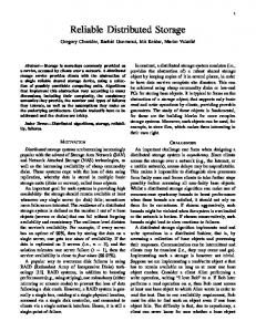
reflected wave
incident wave
Fig. 1 - Reflection on a duct wall. The local impedance control is based on works by Lissek et al.7-9 . It refers to the control of the specific acoustical impedance Z = p/v presented at the diaphragm of a loudspeaker, independently of the neighbouring transducers state. Under a given incidence θ, the reflection coefficient r of an incident sound wave is given by: Z(ω) cos θ − Zc r= (1) Z(ω) cos θ + Zc where Zc = ρc is the characteristic impedance of the surrounding medium. Thus, under normal incidence, an ideal absorber would be controlled so as to get Z(ω) = Zc , yielding r = 0. In parietal conditions, when mounted in the wall of a duct, that is, under grazing incidence, such acoustic absorbers have proved10 to be able to efficiently absorb acoustic energy at low frequenciesf under the condition that the acoustic volume flow produced by the transducer matches the volume flow of the acoustic field in the duct: Z(ω) =
SLS Zc SD
(2)
where SLS is the effective area of the moving diaphragm of the loudspeaker (LS), and SD is the cross sectional area of the duct. The electrodynamic loudspeaker is modelled as a single degree-of-freedom oscillator, with a mechanical impedance: 1 , (3) Zm (ω) = jωM + R + jωC magnetically coupled to an electrical circuit yielding an additional force Bli, where i is the current flowing in the electrical part. Its specific acoustic impedance is thus easily controlled on a wide f
The dimension of the transducer must be much lower than the wavelength, and the sound field is supposed to contain only the fundamental mode: plane waves.
frequency bandwidth around its resonant frequency, using a collocated pressure sensor and a control current11-12 . Given the pressure signal p sensed by the sensor and the target specific acoustical impedance Zat , the control current i to apply is found to be: i(ω) =
2.2
1 Zm (ω) (SLS − )p(ω). Bl Zat (ω)
(4)
Distributed impedance control
y
Active Surface
0
k yi
k yr
x k xr
k xi
Reflected Waves without Control
Incoming Waves Reflected Waves with Control
Acoustic Domain
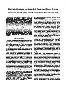
Fig. 2 - Reflection on a duct wall, with and wihout active skin. The distributed approach is based on works by Collet et al.13-14 . It can be depicted as a distributed interface in which a suitable control operator imposes the skin velocity v(x, t) as a function of the measured parietal acoustic pressure field. The objective of the proposed strategy is to cancel the positive group velocity of acoustic waves propagating in interaction with the active skin. Thus all incoming waves intercepting the smart liner only transport energy in the negative (x) direction and becomes evanescent for the positive (x) component of the wave number (see fig. 2). To this end, the imposed normal velocity is composed of two terms: • the first term is proportional to the pressure measured on the boundary at the position of the actuator, and corresponds to a classical local impedance term • the second term imposes a proportional relationship between the pressure gradient along the duct boundary, and the normal acceleration of the transducer diaphragm. In the frequency domain, the control law reads: v(x, ω) =
1 1 ∂p p(x, ω) − (x, ω) ρc jωρ ∂x
(5)
Using the same model of sensor/actuator as for the local control, the control current i for a given unit cell now depends on both the pressure signal p of a collocated sensor and the pressure gradient ∂p/∂x that will be estimated using neighbouring cells pressure sensors: i(ω) =
Zm (ω) Zm (ω) ∂p 1 [(SLS − )p(ω) − ] Bl Zloc (ω) Zdis (ω) ∂x
(6)
where Zloc = ρc is the local impedance term and Zdis = jωρ is a « distributed impedance » operator. Thus, the distributed control can be seen as an extension of the local control in the case Zat = Zc = ρc, with an added term taking into account neighbouring cells. 3
TEST BENCH NUMERICAL MODEL
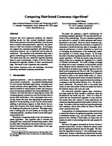
Fig. 3 - Schematics of the test bench model. The test bench is composed of a duct with square cross-sectional area of 10cm×10cm, with a length of 90cm. The unit cell is a square surface, on which a circular loudspeaker is mounted. The unit cell length is 5cm, half that of the cross section width. We use 6 rows of 2 cells to map a part of one of the duct walls, namely between abscissa x=0cm and x=30cm (see figure 1). A correction factor SLS /L2cell is thus applied to the specific acoustical impedances given earlier, in order to take into account the active area to total cell area ratio. An finite element software is used to simulate the propagation of an incident sound field for frequencies ranging from 100Hz to 3200Hz. The domain is meshed with tetrahedral mesh, with minimum element size 6mm and maximum element size λmin /5=c/5fmax =21mm. Quadratic Lagrange elements are used. Control equations and mechanical equations are directly coupled and added to the resulting system, leading to a model with 112997 degrees of freedom in√total. 2 The source is modelled as an ideal point flow source with an amplitude of: Qs = 2 2 Hρc , where H=10cm is the height of the duct, which corresponds to 1Pa RMS amplitude for the pressure, on the fundamental mode (plane waves), for sufficiently low frequencies. The position of this point source is purposely misaligned with the center of the cross section so that other modes can also be excited at higher frequencies. Insertion loss is recovered from the output control section by comparison with a reference case. Perfectly matching layers are used on both ends of the duct in order to simulate non reflecting boundaries.
4
RESULTS
We present the results in terms of insertion loss (IL), in dB. In the reference case, the active skin is replaced with a rigid wall. In the first simulation, the target acoustic impedance for the local impedance control is set to ρc, that is the characteristic specific impedance of the propagating medium (air, in this case). Figure 4 shows the corresponding IL. The simulation is actually carried out twice: once with the local impedance control only (Zdis is set to ∞), and then with the distributed control law, containing both local and distributed terms. 30
Insertion Loss (dB)
25 20 15 10 5 0
local control (ρ.c) distributed control 500
1000
1500
2000
2500
3000
Frequency (Hz) Fig. 4 - Insertion loss (dB) for Zloc = ρc, without (blue ’×’) and with (green ’o’) distributed control.
In the second simulation, the target acoustic impedance for the local impedance control is set to ρc/2. The distributed control is also implemented with Zloc = ρc/2. Figure 5 shows the corresponding IL. 30
Insertion Loss (dB)
25 20 15 10 5 0
local control (ρ.c/2) distributed control 500
1000
1500
2000
2500
3000
Frequency (Hz) Fig. 5 - Insertion loss for Zloc = ρc/2, without (blue ’×’) and with (green ’o’) distributed control.
5
DISCUSSION
In the first case, with Zloc = ρc (see figure 4), both types of control perform relatively well over a wide frequency range: IL over 6dB (maximum at 25dB), between 100Hz and 2500Hz. In the monomodal range (plane waves, up to approximately 1700Hz), the distributed control performs particularly well: the lower the frequency, the higher the IL, from 6dB at 1700Hz to 25dB at 100Hz. The local control, on the other hand, shows a more steady performance: between 6dB and 12dB on the same frequency range, with a peak around 750Hz. The decrease of the performance of the distributed control up to 1700Hz can be explained by the distance between the microphones used to estimate the pressure gradient, two lengths that are less and less negligible compared to the wavelength when the frequency increases. From 1700Hz to higher frequency, both control laws perform similarly. The emergence of higher order propagating modes -(1,0) and (0,1) around 1700Hz, (1,1) around 2400Hz- brings in unpredicted, though favorable behaviour: peaks of insertion loss appear around 1700Hz, 2000Hz and 2400Hz, allowing to keep the IL over 6dB up to almost 2500Hz. For higher frequency (2500-3200Hz), the insertion loss consistently decreases from 6dB to 3dB. It could be explained by the fact that the size of the actuators is no longer negligible compared to the wavelength. In the second case, with Zloc = ρc/2 (see figure 5), the overall performance is further improved. At low frequencies, both strategies show a higher IL. The local control performs even slightly better than the distributed control on the 750-1700Hz range. The high frequency behaviour is quite similar to that previously observed, with higher peaks and lower minima, both control strategies yielding very close IL values. While the distributed term in the complete control law is essentially helping redirecting sound waves toward the source, the local impedance term actually absorbs a great part of the sound field. Thus, both techniques are complementary in the sense that two phenomenon are used: backward reflection, and absorption. It can be anticipated that reflecting the entire incident energy back to the nacelle would amplify structural vibrations, while the presence of important absorption will damp it. 6
CONCLUSION
This paper investigated the performance of a smart structure, namely an active skin for damping the propagation of sound in a duct, using an innovative distributed control approach. Simulation results in terms of insertion loss are very promising. Temporal simulation (not shown in the paper) also showed good performances, but raised the question of the stability of the control, when considering the possible discrepancies between measured mechanical properties of the actuators, and their modelled behaviour. Possible instabilities due to non-plane modes also have to be investigated. An actual prototype of the test bench and of the active skin is being fabricated for experimental validation, which should also help us shed light on these stability issues. 7
ACKNOWLEDGEMENTS The research leading to these results has received funding from the European Community’s
Seventh Framework Programme [FP7/2007-2013] under grant agreement n°604999. 8
REFERENCES 1. M. L. Munjal, “Analysis and design of mufflers—An overview of research at the Indian Institute of Science,” J. Sound Vib., 211, 425–433, (1998). 2. R. Ramakrishnan and W. R. Watson, “Design curves for rectangular splitter silencers,” Appl. Acoust., 35, 1–24, (1992). 3. C. Yilmaz and N. Kikuchi, “Analysis and design of passive low-pass filter-type vibration isolators considering stiffness and mass limitations,” J. Sound Vib., 293, 171–195, (2006). 4. P. A. Nelson and S. J. Elliott, Active Control of Sound, Academic, London, (1992). 5. B. Mazeaud, “Developing of an intelligent sound coating for a duct in the presence of flow,” Ph.D. thesis, Laboratory of Fluid mechanics and Acoustics, Centrale Lyon, (2005). 6. M. A. Galland, B. Mazeaud, and N. Sellen, “Hybrid passive/active absorbers for flow ducts,” Appl. Acoust., 66, 691–708, (2005). 7. H. Lissek, R. Boulandet, and R. Fleury, “Electroacoustic absorbers: bridging the gap between shunt loudspeaker and active sound absorption,” J. Acoust. Soc. Am., 129(5), (2011). 8. H. Lissek, R. Boulandet, and P.-J. René, “Shunt loudspeakers for modal control of rooms,” in Proc. 16th International Congress on Sound and Vibration, (2009) 9. E. Rivet and H. Lissek, “Optimization of electroacoustic resonators for semi-active room equalization in the low-frequency range,” in International Congress of Acoustics 2013, Montreal, Canada, (2013). 10. S. Karkar, E. Rivet, H. Lissek, D. Strobino, A. Pittet, V. Adam, and A. Roux, “Electroacoustic absorbers for the low-frequency modal equalization of a room: what is the optimal target impedance for maximum modal damping, depending on the total area of absorbers?,” in Proc. of Forum Acusticum 2014, Krakow, Poland, (2014). 11. E. Rivet, S. Karkar, and H. Lissek (inventors), “Versatile electroacoustic diffuser-absorber,” GB1421206.2, Intellectual Property Office, United Kingdom, Newport, (2014) (pending). 12. E. Rivet, S. Karkar, and H. Lissek, “Broadband Electroacoustic Absorbers through Hybrid Sensor/Model-Based Active Impedance Control”, IEEE Trans. on Cont. Sys. Tech., in preparation. 13. M. Collet, P. David, and M. Berthillier, “Active acoustical impedance using distributed electrodynamical transducers,” J. Acoust. Soc. Am., 125(2), 882–894, (2009). 14. P. David, M. Collet, and J.M. Cote, “Experimental implementation of acoustic impedance control by 2D network of distributed smart cells,” Smart Materials and Structures, 19(3), 035028 (11pp), (2010).