Transactions of the Indian Ceramic Society
ISSN: 0371-750X (Print) 2165-5456 (Online) Journal homepage: http://www.tandfonline.com/loi/tcer20
Correlation between Microstructure and Mechanical Properties of YSZ/Al2O3 Ceramics and Its Effect on High Speed Machining of Steel Bipin Kumar Singh, Kunal Ghosh, Shibendu Shekhar Roy, Biswanath Mondal & Nilrudra Mandal To cite this article: Bipin Kumar Singh, Kunal Ghosh, Shibendu Shekhar Roy, Biswanath Mondal & Nilrudra Mandal (2018): Correlation between Microstructure and Mechanical Properties of YSZ/Al2O3 Ceramics and Its Effect on High Speed Machining of Steel, Transactions of the Indian Ceramic Society, DOI: 10.1080/0371750X.2018.1528889 To link to this article: https://doi.org/10.1080/0371750X.2018.1528889
Published online: 09 Dec 2018.
Submit your article to this journal
View Crossmark data
Full Terms & Conditions of access and use can be found at http://www.tandfonline.com/action/journalInformation?journalCode=tcer20
Trans. Ind. Ceram. Soc., vol. 77, no. 4, pp. 1-7 (2018). © 2018 Indian Ceramic Society ISSN 0371-750X (Print), ISSN 2165-5456 (Online) http://dx.doi.org/10.1080/0371750X.2018.1528889
Correlation between Microstructure and Mechanical Properties of YSZ/Al2O3 Ceramics and Its Effect on High Speed Machining of Steel Bipin Kumar Singh,1, 2 Kunal Ghosh,1 Shibendu Shekhar Roy,2 Biswanath Mondal1 and Nilrudra Mandal2,* 1
Centre for Advanced Materials Processing, CSIR-Central Mechanical Engineering Research Institute, Durgapur – 713 209, India 2 Mechanical Engineering Department, National Institute of Technology, Durgapur – 713 209, India [MS received February 05, 2018; Revised copy received August 02, 2018; Accepted September 19, 2018]
0.26
720
1.6
690
1.5
CUTTING FORCE (Newton)
0.28 AVERAGE FLANK WEAR (mm)
An attempt has been made to correlate the mechanical properties with microstructure and machining performance of zirconia toughened alumina composite fabricated from different ratios of Al2O3 with yttria stabilized zirconia (YSZ) powder. The developed 3 mol% YSZ powder has been mixed with Al2O3 in the ratios of 10:90, 15:85 and 20:80 for fabrication of cutting inserts. Study reveals the relation between microstructure of the composites with the mechanical properties, i.e. hardness, fracture toughness, flexural strength. Conventional lathe NH-26 is used to evaluate the machining performance, i.e. flank wear, surface roughness and cutting force of all three types of developed inserts by machining of AISI 4340 steel bar. The maximum hardness, 15.55 GPa, has been obtained for 90% Al2O3 with 10% YSZ. The maximum values of fracture toughness (5.96 MPa.m1/2) and flexural strength (510 MPa) are noticed for 80% Al 2O3 with 20% YSZ. The analysis also shows that when the YSZ percentage increases, the smaller grain size of YSZ particle and crack bridging phenomena enhances the mechanical properties like fracture toughness and flexural strength of the composites. The composition comprising of YSZ:Al2O3::10:90 shows less flank wear, best surface finish and lowest cutting force.
660 0.24
630
0.22
1.4 1.3
600 570
0.20
540 0.18 Flank Wear Cutting Force
0.16
Surface Roughness
10
12 14 16 18 20 % OF YTTRIA STABILIZED ZIRCONIA
1.2 1.1
510
1.0
480
0.9
SURFACE ROUGHNESS (m)
ABSTRACT
22
[Keywords: Yttria stabilized zirconia, Alumina, Flank wear, Surface roughness, Cutting force]
Introduction The demand of ceramic products in various industries like manufacturing (cutting tool and dies), automobile, aero systems, biomedical (prosthesis component), etc is rapidly increasing. To fulfill the requirement, lots of research are going on to optimize the composition of ceramics which will improve the properties required for specific application. In this connection, zirconia toughened alumina (ZTA) is one of the attractive ceramic composites which have higher toughness than the conventional ceramics. These high toughness composites may act as substitute to the conventional materials. However, to achieve all the mechanical properties for using it in structural application, it is necessary to find out the exact optimized composition of YSZ and Al2O3. Extensive research have been going on for doping of various additives such as Y2O3,1 Cr2O3,2 MgO3 and CeO24 in toughened alumina for application as inserts, biomedical *Corresponding author; email:
[email protected],
[email protected]
VOL. 77 (4) OCTOBER – DECEMBER 2018
equipment, automobile, aerospace, etc. It has been proved that zirconia particle present in alumina matrix enhances fracture toughness, flexural strength and fatigue strength due to stress-induced phase transformation, i.e. sufficient quantities of the metastable tetragonal phase of zirconia get transformed into monoclinic phase with a volume expansion of ~ 4%.5–8 Hossen et al.9 prepared different composites of zirconia toughened alumina (ZTA) using slurry method. The developed composites were sintered at various temperatures for different sintering time. It was found that density of the developed composite increased with increase in zirconia content and sintering temperature. The hardness and elastic modulus of the developed composite increased with increasing sintering temperature, but decreased with increasing zirconia content. The value of flexural strength improved for both cases. A research carried out by Mandal et al. 10 showed significant improvement in mechanical properties, like hardness, fracture toughness and flexural strength, when 10 vol% Y-PSZ (2.5 mol% Y2O3) was reinforced in -Al2O3 matrix. Vasylkiv et al. 11 studied the mechanical properties of
1
different composites made up of alumina doped tetragonal zirconia stabilized with different percentages of yttria and found that when the percentage of yttria decreased from 3 mol% to 2-1.5 mol% the toughness value was the highest for small percentage of alumina, but with higher percentage of alumina, there was a significant decrease in the toughness of composite. Ragurajan et al.12 studied the mechanical and microstructural properties of aluminium oxide doped in yttria stabilized zirconia. An improvement in the properties was noticed when aluminium oxide was added up to 1.0 wt% with Y-TZP. The maximum density, hardness and toughness of the composite were found as 5.9 g.cm–3, ~13.89 GPa and ~7.2 Mpa m1/2, respectively. The results also illustrate that there is an improvement in Young’s modulus up to 219 GPa with 0.5 wt% addition of aluminium oxide. Casellas et al.13 investigated the effect of coarsening phenomenon into the facture toughness of zirconia toughened alumina ceramics. The grain growth of alumina matrix was enhanced due to the presence of zirconia particles which in turn decreased the hardness of alumina as well as increased the fracture toughness. Recently, Gafur et al.14 investigated the structural and mechanical properties of different composites comprising of alumina and yttria stabilized zirconia and found that the composite containing 5 vol% and 2 vol% 3Y-ZrO2 with alumina had the maximum microhardness and elastic modulus consequently. The maximum values of flexural strength and fracture toughness were obtained for 20 vol% of 3Y-ZrO2 with alumina. The machining behavior of zirconia toughened alumina inserts was well described by Li and Low15 for machining of AISI 4340 steel. Optimization of machining parameters like cutting speed, depth of cut and feed rate on response parameters, i.e. cutting force, surface roughness and flank wear was demonstrated by Mandal et al.16 The wear phenomenon occurred during machining operation was evaluated and described by Azhar et al.17 The present research is focussed to find out the effect of yttria stabilized zirconia (YSZ) in alumina matrix in terms of mechanical and machining properties. For this, different ceramic composites were prepared through combination of co-precipitation and powder metallurgy route with varying percentages of alumina and YSZ. The study first assessed the microstructure, DTA/TGA and XRD to analyse the characteristics of the developed powder. The mechanical properties of all the compositions were investigated to correlate the mechanical properties with the microstructure of the composites. After that, cutting inserts were fabricated with all the compositions while machining AISI 4340 steel to evaluate the performance, i.e. flank wear of the inserts, surface roughness of the job and cutting force generated at the time of machining. In this study, the authors have tried to establish the microstructural effect on the machining performance. Hence, the effect of alumina and YSZ on the performance of the inserts was postulated and optimized material composition was found out towards development of insert
2
which can be used for high speed machining application. This work also gives an insight towards replacement of carbide or coated carbide inserts with the newly indigenously developed inserts in coming days. Experimental Procedure Synthesis of Material In this study, alumina and YSZ powders were prepared separately through co-precipitation method. The chemical used to prepare alumina was aluminium nitrate hexahydrate (Al(NO 3) 3.6H 2O; Sigma Aldrich, USA). Zirconium oxychloride octahydrate (ZrOCl2.8H2O; Loba Chemie, Mumbai, India) and yttrium nitrate hexahydrate (Y(NO3)3.6H2O; Loba Chemie, Mumbai, India) were used for the preparation of yttria stabilized zirconia. Requisite amount of aluminium nitrate solution was taken in a jar and mixed drop wise with dilute NH4OH (~1 M) to form precipitate by maintaining pH ~9. The precipitate was left for 8-10 h for settling down. After that, the gelatinous precipitate was washed with hot water to remove nitrate ions. The nitrate free precipitate was placed in oven for 24 h at 100oC. The dried mass was crushed using mortar pestle followed by calcination at 850oC. After calcination, the powder was wet ball milled using alumina ball (8-10 mm) as a media in planetary mill (Fritsch, Germany). Finally the powder was dried in oven at 100oC. Similar technique was used to prepare YSZ in which requisite amounts of yttrium nitrate and zirconium oxychloride were mixed in a jar; dilute ammonia was mixed to form precipitate. The remaining steps for preparation of YSZ were same as those for alumina. The developed powders were physically mixed by taking requisite amounts according to wt%. Different percentages of alumina and YSZ were wet mixed using pot milling for 48 h with 0.8 wt% of polyethylene glycol 1000 as a plasticizing agent to get uniform distribution. The finally blend homogeneous mixture was again decomposed at 850oC for 1 h. Metallurgical Characterization The morphology and microstructure of the developed composites were characterized through field emission scanning electron microscope (FESEM) (Carl Zeiss SMT Ltd, Germany, model: SUPRA 40) and particle size analyzer (make: Malvern; model: Nano-ZS90). Thermogravimetric analyses of all the developed materials were carried out by TGA/DTA (TA Instrument: DMA, SDT 2960) with a heating rate of 10oC/min up to 1400oC in air atmosphere. This analysis directly links the decomposition reaction of precursor with rise in temperature and helps in deciding the calcination temperature of the precursor. The stabilized phase after sintering was investigated through X-ray diffraction (XRD) analysis, carried out on Shimadzu diffractometer equipped with CuK radiation in the 2 range of 20°-70°. The samples used to carry out XRD analysis were sintered at 1600oC with 1 h dwell time. Surface area and total pore volume of each as-synthesized powder were calculated on Brunnauer-Emmet-Teller (instrument: Surface Analyser: make: Quantachrome, USA).
TRANSACTIONS OF THE INDIAN CERAMIC SOCIETY
(c)
0.8 mm NOSE RADIUS
Performance Evaluation Performance of the developed inserts having different compositions were evaluated on NH-26 lathe (make: HMT Ltd, India) having a speed range of 47-2040 rpm powered by 11 kW motor. A systematic diagram of the same is shown in Fig. 2a. The final shape and size of inserts are portrayed in Fig. 2b. The material used for machining was AISI 4340 steel bar (hardness 40 HRC) with initial diameter and length of 140 mm and 450 mm, respectively. Clamp type tool holder CSBNR2525N43 (make: NTK) was used to clamp the inserts with tool signature of –6o, –6o, 6o, 6o, 15o, 15o and 0.8. To measure the force at the time of machining, piezoelectric dynamometer (make: Kistler; model: 9272) was placed on the tool post just below the tool holder. The forces during machining were analysed by a charge amplifier (make: Kistler; model: 5015 A) connected with a Dynoware software (Fig. 2c). A portable device Surtronic 25 (make: Taylor Hobson; Fig. 2d) was used to measure the surface finish of the machined surface. Toolmakers microscope (make: Leica, Germany) was used to measure the flank wear of each surface after machining the AISI 4340 steel bar.
CUTTING INSERT
8o END R ELIEF ANGLE
125 LENGTH
TOP VIEW
(d)
20 SHANK WIDTH
(a)
75o MAIN CUTTING ANGLE
SID E
(b) (b)
15 o END C UTTING EDGE ANGLE
–6o BACK RACK ANGLE
(CSBNR2020K)
– o RAC 6 KA NGL
TOOL HOLDER
E
(a) (a)
15 o SIDE C UTTING EDGE ANGLE
Fabrication of Cutting Inserts The calcined powders were uniaxially pressed to provide a square shaped part (16166 mm 3) in a die punch arrangement using hydraulic press (make: Carver, USA) at a load of 5 ton.cm–2. The green samples were decomposed to sinter at 1600oC with drench time of 1 h. The sintered samples were shaped on a tool grinder machine with tailor made jig fixture arrangement using diamond wheel. The inserts were slowly polished to shape them as per international standard SNUN 120408 (ISO) and then fine polished with diamond paste (0.5-1.0 m) using bane polisher. The fine polished inserts were imparted with flat angle 20o and width of 0.2 mm to provide strength on edges followed by bevelling or rounding of edges with light honing. Figure 1a shows the picture of tool holder where the developed inserts are fixed. The final shape of developed inserts is shown in Fig. 1b. The details of tool signature were drawn on Auto cad as shown in Fig. 1c.
8o END RELIEF ANGLE
SIDE VIEW
(c)
FRONT VIEW (b)
Fig. 1 – (a) Tool holder (CSBNR2020K), (b) final shape of cutting inserts, (c) tool signature of the developed insert
Mechanical Characterization Bulk density and porosity of the developed composite were measured using Archimedes principle. Hardness of the inserts were measured by Vickers hardness testing machine Innovatest, FALCON-500. The procedure for measurement of hardness and fracture toughness has been illustrated by Singh et al.2 Flexural strengths of the developed composites were measured on universal tensile machine using three-point bending test at a span length of 50 mm and crosshead displacement velocity of 0.5 mm/min. For mechanical characterization, the samples were prepared in rectangular shape (50104 mm 3) by the following procedure: first the calcined powder was blended perfectly with 5 wt% PVA (polyvinyl alcohol) solution for 60 min in ultrasonic machine followed by automatic stirring for 30 min. It was then kept at 100oC to eliminate the water content. The dried powder was compacted in a die punch arrangement at a pressure of 2.5 ton.cm –2. The green compact was placed in a high temperature furnace at a temperature of 1600oC for 1 h.
VOL. 77 (4) OCTOBER – DECEMBER 2018
Fig. 2 – (a) Set up of lathe and job on N-26 lathe, (b) final shape of cutting inserts, (c) Surtronic 25, (d) dynoware with analyser
Results and Discussion Metallurgical and Mechanical Characterization Thermal behavior of alumina and YSZ powders were investigated by DTA/TG analysis in the range of ambient to 1400oC at a heating rate of 10oC·min–1 and the results are portrayed in Figs. 3a and 3b, respectively. The DTA/TG plots clearly illustrate that in both the cases there is incessant weight loss during heating up to 850oC and beyond that, no significant weight loss occurs. The total weight loss in case of alumina was ~28%, and ~20% in case of YSZ. In Fig. 3a the endothermic peak in the range of 70o-150oC is mainly due to the weight loss owing to removal of physically adsorbed water and solvent. Endothermic peaks in the range of 200 o -400 oC are ascribed to dehydroxylation process of -AlOOH to -alumina and decomposition of nitrate present in the dried mass. Exothermic peaks are observed in the range of 600o-1200oC with a minor weight loss, which may be due to the continuation of dehydroxylation process, changes
3
0 –10
–10
–20
–15
200
400 600 800 1000 TEMPERATURE (oC)
1200
..(1)
Im (111) + Im (111) where, Tm =
..(2) Im (111) + It (111) + Im (111)
subscripts m and t denote monoclinic and tetragonal ZrO2, respectively, Vm is monoclinic volume fraction of ZrO2, I denotes integrated intensity w.r.t. diffracting plane, and, Tm is the maximum intensity of m-ZrO2 w.r.t. total ZrO2.
–40 20 0.4
(b)
95
0.2
90 0.0 55 –0.2 80
EXO
100
TG (%)
1.311Tm 100 (1+0.311Tm)
–30
–20
DTA (V/mg)
TG (mg)
–5
DTA (V)
(a)
EXO
10
0
Vm =
INTENSITY (a.u.)
in crystallization or various transition phases of alumina and decay of residual organics. Mondal and Kundu18 in a study found that the phase transition of -alumina started at 900oC and full transformation occurred at ~1200oC. The endothermic peaks beyond 200oC found in the DTA curve of YSZ (Fig. 3b) are due to loss of bound water. The exothermic peak in between 300o and 500oC is mainly due to the transformation of pseudo tetragonal phase of zirconia. But as the temperature increases the transformation of monoclinic to tetragonal phase of zirconia crystals takes place and a wide exothermic peak with sharp endothermic peak around 1200oC is observed.
–0.4
75
–0.6
70 200
400 600 800 1000 TEMPERATURE (oC)
1200
Fig. 3 – DTA/TG curves of (a) Al2O3, (b) YSZ
The XRD analyses of alumina, YSZ, and different composites developed by mixing of alumina and YSZ are presented in Fig. 4. Phase composition, crystallize size, density and grain size of all the composites are presented in Table I. The phase transformation of zirconia, i.e. monoclinic (m-ZrO2) to tetragonal (t-ZrO2) was calculated by using the following equations, from a previous work of Singh et al.:2
30
40 50 2 (degree)
60
70
Fig. 4 – XRD patterns of different wt% of zirconia toughened alumina
Crystallite size (D) of different composites was determined from X-ray line broadening analysis using Scherrer’s formula: D = 0.9/Bcos, where, is the wavelength of radiation, is Bragg’s angle and B is full width at half maximum, and B2 = Bmeas2 – Binst2, where, Bmeas denotes observed full width at half maximum from peak values and Binst is instrumental broadening. From Fig. 4 and Table I it can be observed that when the amount of YSZ increases in alumina, the retention of stabilized zirconia, especially tetragonal zirconia (t-ZrO2), enhances. Hence, it can be concluded that the trend in enhancement of t-ZrO2 shows improvement in density. The analysis also signifies that there is a profound effect of phases and size of particle in the variation of mechanical properties, i.e. hardness, fracture toughness and flexural strength of the developed composites. From Table I it can be clearly noticed that as the percentage of YSZ increases, the grain size of the
Table I : Phase composition, density, crystallite size and grain size of different wt% of ZTA Composition
4
Theoretical density (%)
Bulk density (g.cm–3)
Crystallite size (nm)
Phase composition m-ZrO 2
t-ZrO 2
Average grain size (m)
100% Al2O3+0% YSZ
98.15
4.23
37.12
–
–
1.28
90% Al2O3+10% YSZ
98.08
4.29
38.17
51
49
1.24
85% Al2O3+15% YSZ
97.35
4.48
40.71
47
53
1.08
80% Al2O3+20% YSZ
96.54
4.53
43.23
40
60
1.02
TRANSACTIONS OF THE INDIAN CERAMIC SOCIETY
developed composites decreases; the act of YSZ as a grain growth inhibitor was also found by Azhar et al.17 This is also clearly observed from the FESEM images of the samples (Fig. 5); all the images were taken at same magnification with constant parameters to compare the particle sizes of the composites. Figure 5 also confirms the homogeneous distribution of YSZ in -Al2O3 matrices. EDAX analyses of the samples confirm the quantity of alumina and YSZ. However, a reverse trend is observed for crystallite size of the composites with increasing amount of YSZ (Table I). This may be due to retention of more tetragonal zirconia phases in the crystal. (a)
(b)
3 m
2 m
(d)
(c)
2 m
2 m
Fig. 5 – FESEM images of (a) pure alumina, (b) 90% Al2O3 with 10% YSZ, (c) 85% Al 2O3 with 15% YSZ, (d) 80% Al 2O3 with 20% YSZ
The surface area and total pore volume of the assynthesized powders were determined by BrunnauerEmmet-Teller (BET) calculation. In this system principle of static volumetric technique was used, in which known dose of nitrogen as adsorbate was continuously injected inside the sample holder placed at 77 K. Surface area and total pore volume for 90 wt% alumina with 10 wt% YSZ were determined as 21.339 m2.g–1 and 0.2024 cm3.g–1, respectively. The other two composites showed similar results; surface area and total pore volume for 85 wt% alumina with 15 wt% YSZ were found to be 17.687 m2.g–1 and 0.1378 cm3.g–1, respectively, and those for 80 wt% alumina with 20 wt% YSZ were found to be 17.233 m2.g–1 and 0.1383 cm 3. g–1, respectively. Hence, it may be concluded that the surface area of the developed composites decreases with increasing amount of YSZ.
The mechanical properties of all the composites are presented in Table II; it is clearly observed that metastable tetragonal phase of zirconia present in -Al2O3 matrices has a significant role in improving the hardness and fracture toughness. The hardness of YSZ is lower than the hardness of alumina, hence, with higher percentage of YSZ, lower value of hardness is observed. Similar result was found by Gafur et al.14 However, interesting result is observed with the composite with 10% YSZ which shows increased hardness than that containing 0% YSZ. This result may be due to simultaneous effect of pore mobility rate which restricts the growth of grain at the time of sintering and form smaller grains19 as well as transformation toughening, i.e. retention of metastable tetragonal zirconia particle at the time of sintering.20 Metastable tetragonal phases have the ability to arrest crack propagation but the same capability is not found in the stable tetragonal/cubic phases. Therefore, the hardness of higher doped YSZ shows lower values as portrayed in Table II. From Table II it is observed that maximum value of hardness is obtained for 90 wt% alumina with 10 wt% YSZ, and maximum values of fracture toughness and flexural strength are obtained for 80 wt% alumina with 20 wt% YSZ. These results are in agreement with those of Moraes et al.21 and Gafur et al.,14 where it has been claimed that for any ceramics the size of cracks and defects are responsible for improvement in strength and reliability of ceramics. According to the researchers, two factors – crack bridging and transformation toughening – are responsible for improving toughness and strength. The amount of stabilizer and size of tetragonal particle are considered more significant in the present case, i.e. for transformation of tetragonal particles. Therefore, higher quantity of YSZ shows favourable effect on the toughness and strength of the composite. Performance Evaluation of Inserts Comparative performance of the inserts with three compositions has been judged by the flank wear of the inserts, cutting force developed and the roughness of the job. A previous study carried out by the authors22 revealed the optimized conditions for AISI 4340 steel to get lower power consumption, i.e. lower cutting force with high machinability as: cutting speed: 300 m/min, feed rate: 0.16-0.18 mm/rev, depth of cut: 0.5 mm, which were used for machining all the three types of inserts.
Table II : Hardness, fracture toughness and flexural strength of different wt% of ZTA Composition
Sintering temperature (oC)
Hardness (GPa)
Fracture toughness (MPa.m1/2)
Flexural strength (MPa)
100% Al2O3+0% YSZ
1600
15.10
3.96
438
90% Al2O3+10% YSZ
1600
15.55
5.08
463
85% Al2O3+15% YSZ
1600
15.32
5.72
488
80% Al2O3+20% YSZ
1600
14.84
5.96
510
VOL. 77 (4) OCTOBER – DECEMBER 2018
5
0.26
720
1.6
690
1.5
660 0.24 630 0.22
600 570
0.20
540 0.18
Flank Wear Cutting Force
0.16
Surface Roughness
10
12 14 16 18 20 % OF YTTRIA STABILIZED ZIRCONIA
510
CUTTING FORCE (Newton)
AVERAGE FLANK WEAR (mm)
0.28
480
1.4 1.3 1.2 1.1 1.0
SURFACE ROUGHNESS (m)
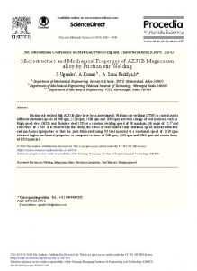
Flank wear, cutting force and surface roughness data of the inserts are portrayed in Fig. 6. It is observed that the value of flank wear increases with the increasing percentage of YSZ in zirconia toughened alumina. Typical images of flank wear for different ZTA composites are presented in Fig. 7. The wear phenomenon of inserts in dry machining has been well illustrated by Casto et al.23 and Mondal.24 According to them, adhesive mechanism and plastic deformation of alumina are the significant factors responsible for wear of inserts. It has been explained that at the time of machining, there is continuous chip and tool interaction due to which a bond is formed between rake face and hot chip, having enough notching capability to pull out the alumina and zirconia grains form the ceramic surfaces. This causes the wear on surface.
0.9
22
Fig. 6 – Variation in average flank wear, cutting force and surface roughness with different percentage of yttria stabilized zirconia
(a)
(b)
(c)
Fig. 7 – Flank wear of (a) 90% alumina with 10% YSZ (b) 85% alumina with 15% YSZ, (c) 80% alumina with 20% YSZ
6
Another important factor causing more wear on the surface is plastic deformation of alumina grain at high temperature. A similar investigation has been carried out by Azhar et al.17 with varying percentages of YSZ in which the authors have captured images of inserts, before and after machining. The results are in agreement with the current research, in which, up to a certain percentage of YSZ, the value of flank wear is less as compared with the higher percentages of YSZ. These results may be due to the replacement of corundum phase of alumina by tetragonal and monoclinic phases which shows less wear for lower percentage of YSZ. Surface roughness of machined surface also plays a vital role in the selection of efficient tool. For any job tool interface, the acceptable value of surface roughness for any insert is 3 m in ideal condition, as mentioned in ISO standard 3685. The experimental data shows that the roughness of machined surface is well below the acceptable limit. Figure 6 suggests that the value of roughness increases with the amount of YSZ. The prime cause of the same is transformation toughening and high hardness at the nose of inserts. The nose radius of insert does not deteriorate with machining time and more and more smooth machined surface is obtained with increasing YSZ. From Fig. 6 it is observed that cutting force also increases with increasing amount of YSZ. These results may be due to high hardness of 90% alumina with 10% YSZ which prevents the deterioration of nose radius and wearing of cutting edge. Conclusions In all the developed composites, the metastable tetragonal phase of zirconia present in -Al2O3 matrices has a significant role in improving the fracture toughness, hardness and flexural strength. The investigation shows that the amount of YSZ strongly pin the grain boundary of alumina. When the percentage of YSZ increases, smaller grain size is formed. The size of cracks and defects are also important for changes in strength and reliability of ceramics. Higher quantity of YSZ shows favourable effect on the toughness and strength of composite. Adhesive mechanism and plastic deformation of alumina has been considered as significant factors responsible for flank wear of inserts which is more predominant when YSZ in alumina increases. The values of roughness and cutting force get increased when the percentage of YSZ increases, due to high hardness of 90% alumina with 10% YSZ which prevents the deterioration of nose radius and wearing of cutting edge. Acknowledgements: The authors heartily thank Prof. (Dr) Harish Hirani, Director, CSIR-Central Mechanical Engineering Research Institute, Durgapur, for his kind support. The authors are grateful to the technical staff (Palash Chowdhury) and research fellows of Centre for Advanced Materials Processing (CAMP) for their kind support to carry out all experiments. The authors acknowledge the financial support of Nanomission, Department of Science and Technology (DST), Govt of India, as a project (SR/NM/NT-1062/ 2015) to execute the research work.
TRANSACTIONS OF THE INDIAN CERAMIC SOCIETY
References 1. N. Mandal, B. Doloi and B. Mondal, Int. J. Refract. Met. Hard Mater., 38, 40-46 (2013). 2. B. K. Singh, B. Mondal and N. Mandal, Ceram. Int., 42, 3338-3350 (2016). 3. A. Z. A. Azhar, H. Mohamed, M. M. Ratnam and Z. A. Ahmad, J. Alloys Compd., 497, 316-320 (2010). 4. B. Mondal, N. Mandal and B. Doloi, Int. J. Appl. Ceram. Technol., 11, 228-239 (2014). 5. J. P. Angle, Z. W ang, C. Dames and M. L. Mecartney, J. Am. Ceram. Soc., 96, 2935-2942 (2013). 6. N. Nakanishi and T. Shigematsu, Mater. Trans. JIM, 32, 778-784 (1991). 7. L. R. F. Rose, Proc. R. Soc. Lond. A, 412, 169-197 (1987). 8. M. Lifeng, Int. J. Solids Struct., 47, 3214-3220 (2010). 9. M. M. Hossen, F. U. Z. Chowdhury, M. A. Gafur and A. K. M. A. Hakim, Int. J. Eng. Res. Technol., 3, 2128-2134 (2014). 10. N. Mandal, B. Mondal, B. Doloi and D. Sengupta, Int. J. Adv. Mater. Manuf. Charact., 3, 137-142 (2013). 11. O. Vasylkiv, Y. Sakka and V. Valeriy, Mater. Trans., 44, 2235-2238 (2003). 12. D. Ragurajan, M. Satgunam, M. Golieskardi, A. A. Albakri and A. K. Ariffin, J. Aust. Ceram. Soc., 52, 72-77 (2016).
VOL. 77 (4) OCTOBER – DECEMBER 2018
13. D. Casellas, M. M. Nag, L. Llanes and M. Anglada, J. Mater. Process. Technol., 143-144, 148-152 (2003). 14. M. A. Gafur, Md S. R. Sarker, Md. Z. Alam and M. R. Qadir, Mater. Sci. Appl., 8, 584-602 (2017). 15. X. S. Li and I. M. Low, J. Mater. Sci. Lett., 12, 1916-1919 (1993). 16. N. Mandal, B. Doloi and B. Mondal, Int. J. Mech. Mater. Eng., 6, 558-568 (2012). 17. A. Z. A. Azhar, M. M. Ratnam and Z. A. Ahmad, J. Am. Ceram. Soc., 478, 608-614 (2009). 18. B. Mondal and S. Kundu, Adv. Appl. Ceram., 105, 222-227 (2006). 19. M. P. Harme, E. W. Robem and R. J. Brook, Trans. Brit. Ceram. Soc., 78, 22-25 (1979). 20. D. Casellas, M. M. Nagl, L. Llanes and M. Anglada, Key Eng. Mater., 127-131, 895-902 (1996). 21. M. C. C. S. Moraes, C. N. Elias, J. D. Filho and L. G. d. Oliveira, Mater. Res., 7, 643-649 (2004). 22. B. K. Singh, H. Roy, B. Mondal, S. S. Roy and N. Mandal, Mach. Sci. Tech., 22, 899-913 (2018). 23. S. L. Casto, E. L. Valvo, E. Lucchini, S. Maschio and V. F. Ruisi, Wear, 208, 67-72 (1997). 24. B. Mondal, Adv. Appl. Ceram., 104, 256-260 (2005).
7