Critical-Mode-Based Soft-Switching Modulation for Three-Phase Inverters Zhengrong Huang1, Zhengyang Liu1, Fred C. Lee1, Qiang Li1, Furong Xiao1,2 1 Center for Power Electronics Systems The Bradley Department of Electrical and Computer Engineering Virginia Polytechnic Institute and State University, Blacksburg, VA, USA 2 School of Automation, Beijing Institute of Technology, Beijing, China Email:
[email protected]
which eliminates the high turn-on loss, although some price is paid on the turn-off loss and conduction loss due to increase of current ripple. With soft-switching, the switching loss of the devices becomes small and high efficiency is achieved, even when the system is operating at hundreds of kHz high frequency.
Abstract—In this paper, a new critical-conduction-mode (CRM)-based modulation is proposed for three-phase inverters. With this modulation, soft switching is achieved and the efficiency of the inverter is improved, especially for high frequency operation with SiC MOSFET. In three-phase string PV inverter applications, by operating at switching frequency above 300 kHz, power density of the inverter is estimated to be at least three times higher than commercial products, while peak efficiency is estimated to be about 99%. Good performance of this proposed modulation is verified with simulation analysis. The results are also experimentally verified on a 25 kW SiCbased three-phase inverter prototype with 80W/in3 power density, and 98.9% peak efficiency is achieved with noninterleaved operation.
Therefore, soft-switching is the key factor to achieve high efficiency at high frequency operation. And CRM operation is the simplest way to achieve soft switching without adding physical complexity to the system. In [10-12], high-frequency CRM control is proposed to achieve soft switching and good power factor on a single-phase AC/DC converter. With inductor current zero-crossingdetection (ZCD) and programmed Toff extension, whole-line ZVS soft switching is achieved in order to reduce switching loss and improve efficiency. With average current mode control, good power factor and low total-harmonic-distortion (THD) are achieved. Experiment results show that with this high-frequency CRM control, 98.5% peak efficiency is achieved with switching frequency above 300 kHz.
Keywords—critical conduction mode (CRM); soft switching; three-phase; high frequency; high efficiency
I. INTRODUCTION Three-phase inverters are widely used in PV applications. For commercial products of three-phase string inverters, the efficiency is usually as high as 97% ~ 99%. However, the power density is usually below 10 ~ 15 W/in3 [1-4]. The power density is limited by Si devices and relatively low switching frequency operation (usually around 20 ~ 30 kHz).
Therefore, in single-phase inverters, CRM soft switching is truly beneficial for high-frequency operation. Then the question is whether CRM soft switching can be implemented in three-phase inverters with good performance at high-frequency operation as well.
With SiC MOSFET, switching frequency can be pushed higher and good performance is still achievable. This is because for similar voltage and current level, SiC devices have better figure-of-merit (FOM), and thus, smaller device related loss, compared with Si devices under the same operating condition. With ten times higher switching frequency, size reduction of passive components, such as inductors and EMI filters, is achieved [5-7], which makes the power density at least three times higher than commercial products by estimation.
However, only two CRM-based ZVS soft-switching methods are found in literature for three-phase inverter/rectifier, based on three-phase H-bridge structure and three-level T-type structure, respectively [13-14]. In both methods, split capacitors are used at DC side, and its middle point is connected to AC side neutral point. With this connection, three phases are electrically decoupled and each phase runs independently at CRM operation. These two methods work well at tens of kHz switching frequency level. While applied into the hundreds of kHz high frequency design, they show very wide switching frequency variation range. Under a typical operating condition (VDC = 800 V, VAC, line-to-line = 480V, P = 12.5 kW), with minimum switching frequency at 300 kHz, the peak switching frequency reaches at least 6 MHz,
For SiC MOSFET, the turn-off loss is much smaller than the turn-on loss [8-10], which makes critical conduction mode (CRM) become the preferred operation mode for SiC MOSFET. This is because with CRM operation, zero-voltageswitching (ZVS) turn-on of the control switch is achievable,
978-1-5090-2998-3/17/$31.00 ©2017 IEEE
167
causing significantly large switching related loss. Therefore, these two methods are not suitable for the high frequency design.
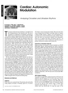
In DPWM, the whole line cycle is equally divided into six time regions. In each time region, one phase is clamped to positive or negative DC bus. The clamping options in line cycle are shown in Fig. 2(a). Take 0 ~ 60 degree as an example. During this 60-degree time region, phase B is clamped to the negative DC bus as shown in Fig. 2(b), which is denoted as “B to N” in Fig. 2(a). The original purpose of this DPWM clamping is to avoid switching actions around the peak region of AC reference current. Here a more important reason to adopt DPWM is to enable CRM soft switching. Since at any instant, one phase is clamped, or saying, no switching, and thus no switching loss exists in this phase no matter what current waveform in this phase, while the other two phases can operate at CRM. As long as the average AC currents in these two phases are well controlled as sinusoidal shape, the third phase also has good sinusoidal average AC current.
The wide switching frequency variation range is an intrinsic characteristic of single-phase CRM operation in inverter/rectifier. The decoupling connection between DC side middle point and AC side neutral point halves the DC side voltage in the equivalent circuit, which makes the duty cycle variation range over line cycle become very wide (almost from 0 to 1 after decoupling). Since in CRM operation, switching frequency depends on duty cycle if only the DC voltage changes while other parameters all unchanged. The very wide duty cycle variation range makes the switching frequency range extremely wide, which is unacceptable. The research goal is by using SiC MOSFET, pushing switching frequency to several hundreds of kHz to achieve higher power density, while still maintaining high efficiency. The main challenge is to find a solution of CRM-based soft switching modulation for three-phase inverters, which is suitable for the high frequency design to achieve high efficiency. Therefore, in this paper, the exploration process of suitable solution is discussed in Section II. The new softswitching modulation is proposed and discussed in Section III. The application of two-channel interleaving is discussed in Section IV. Finally, experimental verification of the proposed modulation is shown in Section V. II. COMBINATION OF CRM WITH DISCONTINUOUS-PULSEWIDTH-MODULATION (DPWM) The issue of wide switching frequency variation range results from the decoupling connection, so a simple solution is to disconnect the DC side middle point and AC side neutral point to avoid this decoupling. Since two-level H-bridge structure shown in Fig. 1 is the simplest topology for threephase inverter/rectifier, the analysis below is based on this structure. However, in this structure, three phases are not decoupled and only two phases are independent, that is, AC current of the third phase is determined by the summation of AC current of the first two phases. This is in conflict with three-phase CRM operation, which requires each phase operate at CRM independently. To solve this conflict, traditional discontinuous pulse width modulation (DPWM) concept is adopted to enable the CRM operation [15].
(a)
(b) Fig. 2. (a) Line cycle DPWM clamping options (b) 0 ~ 60 degree DPWM clamping option in circuit
Therefore, by combining DPWM with the CRM control proposed in [10], the control diagram of this DPWM-based CRM modulation (called “DPWM + CRM” for short) during the first 60-degree time region is shown as an example in Fig. 3. Here phase B is clamped to negative DC bus, while phase A and phase C operate at CRM independently. In phase A and phase C, the inductor current zero crossing detection (ZCD) part and programmed off-time extension is used to determine Fig. 1. Three-phase H-bridge structure
168
control switch turn-on instant and achieve ZVS soft switching, and average current loop is used to determine on-time and turnoff instant, achieving good sinusoidal AC average current and good power factor. Both phase A and phase C are controlled independently using above average-current-mode-based CRM concept.
making the turn-on instant of phase A synchronize to that of phase C, which means the turn-on of both phase A and phase C are determined by the inductor current zero crossing of phase C. The waveforms of gate signals and inductor currents in phase A and phase C are shown in Fig. 5(a) for better illustration. During 30 ~ 60 degree, phase C should run at DCM operation, while phase A still runs at CRM operation. Turn-on instants of phase A and phase C are both determined by inductor current zero crossing of phase A. All the analysis above can be applied to the whole line cycle. The operation mode distribution of the three-phase inverter/rectifier with above modulation (called “DPWM + CRM + FS sync” for short) in whole line cycle is shown in Fig. 5(b).
Fig. 3. DPWM + CRM control scheme in 0 ~ 60 degree
With this DPWM + CRM modulation, however, the switching frequency variation range is still very wide. With minimum switching frequency is 300 kHz, the peak switching frequency is about 3 MHz. The switching frequency distribution in half line cycle is shown in Fig. 4. This wide switching frequency variation range still causes large switching related loss, which is unacceptable.
(a)
Fig. 4. DPWM + CRM switching frequency distribution in half line cycle
III. SYNCHRONIZATION OF SWITCHING FREQUENCY According to Fig. 4, the MHz switching frequency only happens in one phase at any instant. In order to limit the switching frequency in this phase, one simple way is to change the operation mode in this phase from CRM operation to discontinuous conduction mode (DCM) operation. Take the first 30-degree of the half line cycle as an example. The switching frequency of phase A is much higher than that of phase C. Therefore, by changing the operation mode of phase A to DCM operation, the switching frequency of phase A can be reduced. For the simplicity of control, the switching frequencies of phase A and phase C are synchronized by
(b) Fig. 5. After switching frequency synchronization: (a) Switching cycle waveforms (b) Line cycle operation mode
169
The control diagram of the proposed “DPWM + CRM + FS sync” modulation is shown in Fig. 6, taking 0 ~ 30 degree as an example. The difference between Fig. 6 and Fig. 3 is that here the inductor current zero crossing point of the phase operating in CRM becomes the global decision point to turn on the control switches, instead of the individual inductor current zero crossing point in each phase. That is exactly what synchronization means.
crossing point, both phase A and phase C participate the LC resonance, and the equivalent circuit become a 4th-order circuit, which is hard to find analytical solutions of inductor currents and device junction capacitor voltages. What is more, the initial condition of phase A in this 4th-order LC resonance circuit is hard to identify, which also adds to complexity of circuit analysis. Therefore, simulation is used for ZVS analysis. Take phase C as an example and first do analysis during CRM operation (0 ~ 30 degree in half line cycle). Three instants: t1, t2 and t3 are arbitrarily selected and the zoomed-in waveforms of gate signal, inductor current and drain-source voltage of control switch are shown respectively in Fig. 8. At each instant, drainsource voltage is able to be discharged to zero before control switch turn-on. This is true for any instant during the first 30 degree, which indicates that ZVS is achieved naturally during CRM operation. For 90 ~ 120 degree, phase C also operate at CRM and same conclusion is drawn.
Fig. 6. “DPWM + CRM + FS sync” control scheme in 0 ~ 30 degree
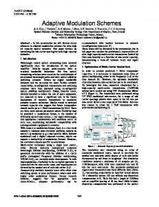
After the synchronization, there is significant change in switching frequency with the minimum frequency at 300 kHz. Comparison of switching frequency variation in three phases before (in gray) and after synchronization (in multicolor) over half line cycle is shown in Fig. 7. The switching frequency variation range also shrinks, with peak switching frequency around 500 kHz, which significantly reduces switching related loss.
Fig. 8. ZVS simulation analysis during CRM operation
Then to analyze whether ZVS is achieved during DCM operation. Still use first 30 degree as an example, when phase A is operating at DCM and phase C is operating at CRM. The turn-on instant of phase A is synchronized to phase C, which means, determined by another phase. Therefore, drain-source voltage of phase A is not necessarily able to be discharged to zero before control switch turn-on, which means ZVS is not necessarily achievable and DCM turn-on loss exists. However, simulation results show that if phase A’s control switch is turned on slightly after phase C’s control switch is turned on, that is, a short delay is applied onto the turn-on instant of phase A, instead of exact synchronization to phase C’s turn-on instant, then the drain-source voltage of phase A’s control switch will be decreasing and finally reach a valley value. This valley value is always smaller than 50V with 800VDC and 480VAC (line-to-line). Then the DCM turn-on loss can be minimized by turning on the control switch when drainsource voltage reaches this valley value.
Fig. 7. Switching frequency comparison before and after synchronization
Another important aspect of the performance with this modulation is whether ZVS is achieved during whole line cycle. Take the first 30 degree as an example. Here phase A is operating at DCM, phase C is operating at CRM, and phase B is clamped to negative DC bus. After phase C inductor current zero crossing point, the LC resonance between the inductor and the junction capacitor of devices begins, which helps to discharge control switch junction capacitor. However, phase A inductor current touches zero and starts LC resonance earlier than phase C. Therefore, after phase C inductor current zero
Fig. 9 shows the switching cycle simulation waveforms in phase A and phase C during first 30 degree, including gate signal, inductor current and drain-source voltage. It can be seen that with the turn-on delay in phase A (highlighted in green color), phase A’s drain-source voltage is also discharged to zero, which means phase A also achieves ZVS.
170
Fig. 11. Circuit of three-phase inverter with two legs in each phase
However, as power goes higher, the current ripple also goes larger, and large current ripple is a drawback of CRM operation, which not only adds to the burden and increase the size of harmonic filter before AC side, but also causes large DM noise and require large DM EMI filter. Therefore, interleaving concept is widely used for current ripple cancellation and thus harmonic and DM EMI filter size reduction. Two-channel interleaving is simplest and most common, and the open-loop interleaving control method [10] [16-17] is applied in single-phase CRM AC/DC converter. It is experimentally verified that after interleaving, the corner frequency of DM EMI filter has an eight-time increase, which indicates significant DM EMI filter size reduction [18-21].
Fig. 9. Switching cycle simulation waveforms in phase A and phase C during first 30 degree
Although from simulation results, ZVS is not necessarily achieved during DCM operation and there is some DCM turnon loss due to DCM non-ZVS, compared with the total power, this part of loss is negligible. Fig. 10 shows the total device loss comparison before and after switching frequency synchronization based on simulation results, with all the device parameters coming from manufacture datasheet. The negligible DCM turn-on loss can be clearly seen. Besides DCM turn-on loss, conduction loss is slightly increased due to the increase of current RMS value at DCM operation; switching related loss is reduced due to switching frequency reduction. The total device loss is slightly reduced to around 0.5% of total power, which indicates the proposed modulation is a high-efficiency solution, even at 300 ~ 500 kHz high frequency operation.
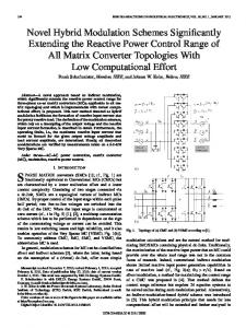
Here two-channel interleaving is also applied in three-phase inverter with DPWM + CRM + FS sync modulation. From simulation results, under same power, compared with noninterleaved operation (in-phase operation), not only total AC current ripple cancellation is achieved, but also inductor current ripple reduction is observed during clamping time region, which is shown in Fig. 12 with current defined in Fig. 11. From simulation analysis, about 20% conduction loss reduction is achieved due to inductor current ripple reduction.
(a)
Fig. 10. Total device loss comparison before and after synchronization
IV. APPLICATION OF TWO-CHANNEL INTERLEAVING For higher power application, one or more phase legs (channels) can be added into each phase. Here Fig. 11 shows the circuit diagram of H bridge structure, with two phase legs in each phase as an example.
(b) Fig. 12. Inductor current waveforms and total AC current waveforms (a) before interleaving (b) after interleaving
171
After interleaving, the switching frequency variation range becomes slightly wider. With minimum switching frequency at 300 kHz, the peak switching frequency is around 700 kHz. This is because the voltage at AC common node, and thus the volt-second applied on the inductor, is different from noninterleaved operation. As for ZVS, after interleaving, ZVS is still achievable during CRM operation, but DCM turn-on loss becomes larger, even if a short turn-on delay is applied to the phase operating at DCM. This is because the equivalent circuit during LC resonance is different from that in non-interleaved operation. Total device loss increases by 0.2% of total power after interleaving. Detailed analysis about the comparison of switching-cyclebased operation, LC resonance process and equivalent circuit will be included in future publication.
Fig. 14. Line-cycle experiment waveforms of inductor currents and line currents in three phases at non-interleaved operation
V. EXPERIMENT RESULTS According to the system diagram in Fig. 11, a 25 kW threephase inverter prototype is built with SiC MOSFET, which is shown in Fig. 13. The SiC MOSFET used in this prototype is from GE with DE-150 package, which is very suitable for hundreds of kHz high frequency application. (Refer to [10] for detailed device parameters) Power density of this prototype is 80 W/in3, including all voltage and current sensors, heat sinks, DC bulk caps and LC harmonic filters. The peak efficiency is estimated to be about 99% with the proposed modulation operating at switching frequency above 300 kHz. The inductance required for non-interleaved operation is 3.5ȝH, and 5.3ȝH required for interleaved operation. The control is implemented digitally with one microcontroller (MCU), TMS320F28075, from TI, and the control cycle, or the interrupt service routine (ISR) period is 3ȝs.
Fig. 15. Switching-cycle experiment waveforms of gate signal, inductor current and drain-source voltage during CRM mode at non-interleaved operation
Fig. 16 shows the typical switching-cycle experiment waveforms at 3 instants during DCM operation, including gate signal, inductor current and control switch drain-source voltage. It can be seen that at each instant, before control switch is turned on, the drain-source voltage has already reached valley value that is close to zero, which verifies that DCM turn-on loss is minimized.
Fig. 13. Prototype of 25 kW SiC-based three-phase inverter
For non-interleaved operation (full power = 12.5 kW), Fig. 14 shows the typical line-cycle experiment waveforms of inductor currents and line currents (average currents) in three phases. The measured THD% of the line currents in three phases is 3.3%, which indicates the line currents in three phases are well controlled as sinusoidal shapes. Fig. 15 shows the typical switching-cycle experiment waveforms at 3 instants during CRM operation, including gate signal, inductor current and control switch drain-source voltage. It can be seen that at each instant, before control switch is turned on, the drain-source voltage has already been discharged to zero, which verifies the ZVS is achieved during CRM operation.
Fig. 16. Switching-cycle experiment waveforms of gate signal, inductor current and drain-source voltage during DCM mode at non-interleaved operation
172
Fig. 17 shows the efficiency test results under 800VDC, 480VAC (line-to-line) and different power at non-interleaved operation (full power = 12.5 kW). The peak efficiency is 98.9%, which verifies that the proposed modulation is a highefficiency solution. This efficiency is similar or slightly better than that of commercial products. Some optimizations are still needed to be done and will be talked about in future publication.
efficiency under nominal condition will be included in future publication.
Fig. 19. Preliminary test results of gate signal, drain-source voltage and inductor current in one phase during CRM mode at interleaved operation
Fig. 17. Efficiency test results under rated condition at non-interleaved operation
For interleaved operation (full power = 25 kW), there are some preliminary scale-down test results. Fig. 18 shows the waveforms of inductor currents and total current in phase A. It can be seen that good interleaving is achieved during both CRM and DCM operation.
Fig. 20. Preliminary test results of gate signal, drain-source voltage and inductor current in one phase during DCM mode at interleaved operation
VI. CONCLUSIONS In this paper, a new CRM-based soft-switching modulation (DPWM + CRM + FS sync.) for three-phase inverters is proposed, which is able to achieve ZVS, reduce switching related loss and improve efficiency especially at several hundreds of kHz high frequency operations with SiC MOSFET. Two-channel interleaving is beneficial for current ripple cancellation and filter size reduction, and is applied in this three-phase inverter. Simulation results verify the good performance of this modulation, and the control function is verified on a 25 kW three-phase inverter prototype with 80W/in3 power density. For non-interleaved operation, the tested peak efficiency is 98.9% with proposed modulation operating at switching frequency ranging between 300 kHz and 500 kHz.
Fig. 18. Preliminary test results of inductor currents and total current in one phase at interleaved operation
Also, Fig. 19 and Fig. 20 show the switching-cycle experiment waveforms in one phase leg during CRM operation and during DCM operation, respectively, including gate signal, drain-source voltage of control switch, and inductor current. Here CRM and DCM operation zone are marked on AC line current, IAC, using green and purple color respectively. It can be seen that ZVS is achieved during CRM operation. During DCM operation, ZVS is not achieved and thus some DCM turn-on loss exists. The valley point switching concept in noninterleaved operation will be applied and the test results and
REFERENCES [1]
173
Solar inverters, SMA America, http://www.sma-america.com/products /solarinverters.html
[2]
PV inverters, Yaskawa Solectria Solar, https://solectria.com/pvinverters/ [3] Solar inverters, ABB, http://new.abb.com/power-converters-inverters/ solar [4] PV inverters, Sungrow, http://en.sungrowpower.com/product/ [5] M. Mu, F. C. Lee, “Comparison and optimization of high frequency inductors for critical model GaN converter operating at 1MHz,” Electronics and Application Conference and Exposition (PEAC), 2014 International, pp. 1363, 1368, 5-8 Nov. 2014. [6] Y. Yang; M. Mu; Z. Liu, F. C. Lee, Q. Li, “Common mode EMI reduction technique for interleaved MHz critical mode PFC converter with coupled inductor,” in Proc. IEEE Energy Convers. Congr. Expo., 2015, pp. 233–239. [7] D. Hou, Y. Su, Q. Li, F. C. Lee, “Improving the efficiency and dynamics of 3D integrated POL,”, in Proc. IEEE Appl. Power Electron. Conf., 2015, pp. 140–145. [8] C. DiMarino, Z. Chen, M. Danilovic, D. Boroyevich, R. Burgos and P. Mattavelli, "High-temperature characterization and comparison of 1.2 kV SiC power MOSFETs," Energy Conversion Congress and Exposition (ECCE), 2013 IEEE, Denver, CO, 2013, pp. 3235-3242. [9] C. DiMarino, Z. Chen, D. Boroyevich, R. Burgos and P. Mattavelli, "Characterization and comparison of 1.2 kV SiC power semiconductor devices," Power Electronics and Applications (EPE), 2013 15th European Conference on, Lille, 2013, pp. 1-10. [10] Z. Liu, B. Li, F. C. Lee and Q. Li, "Design of CRM AC/DC converter for very high-frequency high-density WBG-based 6.6kW bidirectional on-board battery charger," Energy Conversion Congress and Exposition (ECCE), 2016 IEEE, Milwaukee, WI, 2016, pp. 1-8. [11] Y. Yang, Z. Liu, F. C. Lee and Q. Li, "Multi-phase coupled and integrated inductors for critical conduction mode totem-pole PFC converter," 2017 IEEE Applied Power Electronics Conference and Exposition (APEC), Tampa, FL, 2017, pp. 1804-1809. [12] B. Li, F. C. Lee, Q. Li and Z. Liu, "Bi-directional on-board charger architecture and control for achieving ultra-high efficiency with wide battery voltage range," 2017 IEEE Applied Power Electronics Conference and Exposition (APEC), Tampa, FL, 2017, pp. 3688-3694.
[13] D. Zhang, Q. Zhang, H. Hu, A. Grishina, J. Shen, and I. Batarseh, “High efficiency current mode control for three-phase micro-inverters,” in Proc. IEEE Energy Appl. Power Electron. Conf. Expo., Feb. 2012, pp. 892–897. [14] D. Leuenberger, D. Christen, and J. Biela, “Triangular Current Mode Operation of a Three Phase Interleaved T-Type Inverter for Photovoltaic Systems,” in Proc. PCIM Europe, 8- 10 May, Nuremberg, 2012. [15] J. W. Kolar and U. Drofenik, "A new switching loss reduced discontinuous PWM scheme for a unidirectional threephase/switch/level boost-type PWM (VIENNA) rectifier," Telecommunication Energy Conference, 1999. INTELEC '99. The 21st International, Copenhagen, 1999, pp. 490 pp..doi: 10.1109/INTLEC.1999.794128. [16] T. Ishii and Y. Mizutani, “Power factor correction using interleaving technique for critical mode switching converters,” in Proc. 29th Annu. IEEE Power Electron. Specialists Conf., May 1998, pp. 905–910. [17] L. Huber, B. T. Irving, and M. M. Jovanovic, “Open-loop control methods for interleaved DCM/CCM boundary boost PFC converters,” IEEE Trans. Power Electron., vol. 23, no. 4, pp. 1649–1657, Jul. 2008. [18] Z. Liu, Z. Huang, F. C. Lee and Q. Li, “Digital-Based Interleaving Control for GaN-Based MHz CRM Totem-Pole PFC,” in IEEE Journal of Emerging and Selected Topics in Power Electronics, vol. 4, no. 3, pp. 808-814, Sept. 2016. [19] Z. Liu, F. C. Lee, Q. Li and Y. Yang, "Design of GaN-Based MHz Totem-Pole PFC Rectifier," in IEEE Journal of Emerging and Selected Topics in Power Electronics, vol. 4, no. 3, pp. 799-807, Sept. 2016. [20] Z. Liu, Z. Huang, F. C. Lee, Q. Li and Y. Yang, "Operation analysis of digital control based MHz totem-pole PFC with GaN device," 2015 IEEE 3rd Workshop on Wide Bandgap Power Devices and Applications (WiPDA), Blacksburg, VA, 2015, pp. 281-286. [21] Z. Huang, Z. Liu, Q. Li and F. C. Lee, "Microcontroller-based MHz totem-pole PFC with critical mode control," 2016 IEEE Energy Conversion Congress and Exposition (ECCE), Milwaukee, WI, 2016, pp. 1-8.
174