This article has been accepted for publication in a future issue of this journal, but has not been fully edited. Content may change prior to final publication. Citation information: DOI 10.1109/ACCESS.2017.2688019, IEEE Access 1
NOMA Based Spatial Modulation Xudong Zhu, Zhaocheng Wang and Jianfei Cao
Abstract—Spatial modulation (SM) has emerged as a lowcomplexity and energy-efficient multiple-input multiple-output (MIMO) transmission technique, where the information bits are not only transmitted by amplitude phase modulation (APM) but also conveyed by the index of activated transmit antenna (TA). By deploying SM in downlink multi-user (DL-MU) scenarios, conventional orthogonal multiple access based SM (OMASM) allocates exclusive time-frequency resources to users, but suffers from low spectral efficiency. TA grouping based SM (TAG-SM) divides TAs into sub-groups to serve different users independently, but suffers from severe inter-user interference. By introducing non-orthogonal multiple access (NOMA) into SM for DL-MU transmission, NOMA based SM (NOMA-SM) is proposed to mitigate inter-user interference, while maintain high spectral efficiency. Specifically, by applying successive interference cancellation (SIC) at user side, the inter-user interference could be effectively eliminated with the sacrifice of increased computational complexity. Afterwards, based on symbol error rate (SER) analysis, a low-complexity power allocation scheme is provided to achieve high spectral efficiency through power domain multiplexing. When considering near-far effect from user distribution, user pairing issue is also discussed. Numerical simulation compares NOMA-SM with OMA-SM and TAG-SM, and verifies the effectiveness of the proposed low-complexity power allocation and user pairing methodologies. Index Terms—Spatial modulation (SM), non-orthogonal multiple access (NOMA), successive interference cancellation (SIC), multiple-input multiple-output system (MIMO), downlink multiuser (DL-MU).
I. I NTRODUCTION To meet the escalating demand of wireless data traffic by smart phones, tablets and various applications such as live web cast and cloud computing, the cellular network has been densified to improve the spectral efficiency [1], [2]. At the same time, considering the requirement to curtail the carbon emission, energy reduction of base stations (BSs) in future 5G cellular network is of great importance [3], [4]. A typical BS for cellular network consists of baseband processors, radiofrequency (RF) chains and transmit antennas (TAs), where energy consumption mainly comes from the power amplifiers (PAs), which are equipped in each RF chain [5]. The energy consumption challenges the application of conventional MIMO schemes, which requires the same number of RF chains as TAs [6], [7]. X. Zhu and Z. Wang are with Tsinghua National Laboratory for Information Science and Technology (TNList), the Department of Electronic Engineering, Tsinghua University, Beijing 100084, China (e-mail:
[email protected];
[email protected]). J. Cao is with SONY China Research Laboratory, Beijing 100084, China (e-mail:
[email protected]). This work was supported by National Natural Science Foundation of China (Grant No. 61571267), Shenzhen Subject Arrangements (JCYJ20160331184124954), Shenzhen Peacock Plan (No. 1108170036003286), Shenzhen Fundamental Research Project (JCYJ20150401112337177), Sony Corporation and Sony China Research Laboratory, Sony (China) Ltd.
Spatial modulation (SM) has emerged as a low-complexity and energy-efficient MIMO transmission technique for future 5G cellular network [8]–[12]. Specifically, SM is a point-topoint single-stream transmission scheme, where the bit stream is divided into groups and each group consists of two parts: 1) the first part of bit information is mapped to the index of activated TA to transmit a signal while other TAs remain silent; 2) the second part of bit information is mapped to a symbol from the conventional amplitude and phase modulation (APM) constellation diagram, which will be radiated through the activated TA. Compared with the conventional MIMO schemes which require the same number of RF chains as TAs, SM enjoys high energy efficiency due to the fact that only one or a small number of RF chains are required, regardless of the number of TAs [8]–[12]. By introducing the additional transmission channel by TA index, the spatial multiplexing gain of SM schemes is comparable to the conventional multistream MIMO schemes [13], [14]. The classical SM schemes, such as space shift keying (SSK) [8], generalized SM (GSM) [9], [10], trellis coded SM (TCSM) [11] and their variants are all devoted to a point-to-point MIMO transmission scenario. Since a BS typically serves multi-user (MU) within the cell, classical SM schemes should evolve to support MU transmission for cellular networks [1]–[4]. For uplink MU (UL-MU) transmission, each user adopts SM independently and the BS with multiple receive antennas (RAs) could separate the signals from different users at the cost of increased detection complexity [15]–[17]. Several strategies have been proposed to achieve a trade-off between detection performance and computation complexity, e.g., message passing based low-complexity detection algorithm [15], massive MIMO with low-resolution analog-to-digital convertors (ADCs) [16] and compressive sensing (CS) aided detection scheme [17]. For downlink MU (DL-MU) transmission, conventional orthogonal multiple access (OMA) techniques, e.g., time division multiple access (TDMA) and frequency division multiple access (FDMA), could be directly combined with SM schemes (named OMA-SM), but suffer from low spectral efficiency due to exclusive time-frequency resource allocation. Besides division over time and frequency domains, TA domain division could also be utilized for multiple access [18]–[20]. Specifically, TAs at the BS are divided into several groups and each group of TAs are utilized to implement SM transmission for different users independently. Different from user orthogonal property over time and frequency domains, such TA grouping based SM (TAG-SM) schemes suffer from severe inter-user interference. Precoding schemes based on power allocation are proposed to suppress such inter-user interference by assuming channel state information (CSI) at the BS [18], [19]. By introducing adaptive TA selection instead of fixed TA grouping procedure, spectral efficiency could be
2169-3536 (c) 2016 IEEE. Translations and content mining are permitted for academic research only. Personal use is also permitted, but republication/redistribution requires IEEE permission. See http://www.ieee.org/publications_standards/publications/rights/index.html for more information.
This article has been accepted for publication in a future issue of this journal, but has not been fully edited. Content may change prior to final publication. Citation information: DOI 10.1109/ACCESS.2017.2688019, IEEE Access 2
further improved [20], [21]. Moreover, a layered SM scheme for DL-MU transmission is proposed in [22], where user bit streams are combined and then transmitted in a broadcast way with low spectral efficiency. Therefore, inter-user interference and spectral efficiency become two bottlenecks in DL-MU transmission, while existing SM based DL-MU transmission schemes could only achieve one issue, whereas suffer from the other [18]–[22]. To achieve higher spectral efficiency for 5G cellular networks, a non-orthogonal multiple access (NOMA) over power domain has been proposed as a promising solution [23], [24]. Unlike traditional OMA techniques, where exclusive timefrequency resource are allocated, NOMA integrates different users’ data in the power domain. At user side, successive interference cancellation (SIC) should be deployed to remove the inter-user interference before data detection [23]. The NOMA performance for DL-MU transmission in a cellular network has been analytically investigated through the outage probability and ergodic sum rate, which has verified the performance gain by NOMA over its traditional OMA counterparts [25]. The power allocation problem among users for NOMA is discussed in [26], where users with poor channel conditions are allocated with more power to detect their signal directly while users with favorable channel conditions are allocated with less power to facilitate the SIC procedure. The impact of user pairing is studied in [27], which indicates that users with more distinctive channel conditions should be paired, which could achieve higher spectral efficiency. In this paper, by introducing NOMA [23], [24] into DLMU transmission combined with SM methodology, NOMASM is proposed to achieve high spectral efficiency for 5G cellular networks, meanwhile inter-user interference is handled by SIC procedure at user side. Different from neither OMASM nor TAG-SM [18]–[20], where exclusive time-frequency or TA resource are allocated to different users, NOMA-SM utilizes the same time-frequency and TAs to serve MU with carefully designed power allocation. The main outcome and contribution of our paper are summarized as follows. • Overview of OMA-SM and TAG-SM: A brief overview of OMA-SM and TAG-SM [18]–[20] is provided as counterparts of the proposed NOMA-SM scheme. OMA-SM allocates exclusive time-frequency resource to different users, but suffers from low spectral efficiency. TAG-SM divides TAs into sub-groups to serve users independently, which is able to improve the spectral efficiency compared to OMA-SM. However, inter-user interference is introduced due to TA domain division, which leads to a detection error floor at user side. • NOMA-SM design: By combining NOMA with SM for DL MU transmission, the proposed NOMA-SM design is able to improve the spectral efficiency compared to TAGSM. Signals intended to different users are integrated at power domain and then radiated through the same timefrequency and TA resource. By deploying SIC based detection scheme, inter-user interference could be mitigated at the cost of increased computational complexity. Compared with OMA-SM and TAG-SM, NOMA-SM achieves a better trade-off between spectral efficiency and
•
interference mitigation. Performance analysis and practical considerations: Firstly, theoretical symbol error rate (SER) analysis is presented, which indicates the error propagation issue among users due to the SIC procedure. Afterwards, the power allocation issue is formulated as optimization problems to minimize the maximum SER or minimize the average SER. Based on the SER analysis for NOMA-SM, a low-complexity power allocation scheme is proposed to achieve high spectral efficiency through power domain multiplexing. Moreover, by considering near-far effect from user distribution, user pairing is also discussed.
In simulation, theoretical SER analysis is firstly verified. After that, we demonstrate that the proposed low-complexity power allocation scheme is able to provide acceptable performance compared to simulation results. BER performance comparison between OMA-SM, TAG-SM and the proposed NOMA-SM is presented in detail. The rest of the paper is organized as follows. In Section II, a brief overview of OMA-SM and TAG-SM for DL-MU transmission is presented as counterparts of NOMA-SM. Section III details the principle of NOMA-SM, including transmitter, receiver and its performance comparison with OMA-SM and TAG-SM. Section IV provides the performance analysis of NOMA-SM over SER approximation, power allocation and user pairing. Our simulation results indicating the benefits of NOMA-SM are presented in Section V, while our conclusions are drawn in Section VI. Throughout this paper, boldface lower and upper-case symbols represent vectors and matrices, respectively. We use (·)T ∗ H for transpose, (·) (·) for complex conjugate, (·) for conjugate transpose, · for the binomial coefficient and || · ||p for the p-th order norm of a vector/matrix. We use CN (µ, σ 2 ) for the complex Gaussian distribution of a random variable, having independent Gaussian distribution real and imaginary parts 2 2 denoted by N (µ, σ2 ), with mean µ and variance σ2 . We use P (·) for the probability of an event and Ex {·} for the statistical expectation with respect to x. We use log(·) for the natural logarithm and loga (·) for the logarithm with base a. II. OVERVIEW OF OMA-SM
AND
TAG-SM
A. OMA-SM for DL-MU Transmission In this paper, DL-MU transmission is considered, where the BS is equipped with Nt TAs to serve K users [1], [2]. We assume that all users have Nr RAs to receive the DL signal. Rayleigh fading channel between the BS and the k-th user (1 ≤ k ≤ K) [18]–[20] is considered as (k)
H(k) = [h1 (k)
(k)
(k)
h2
(k)
· · · hNt ] ∈ CNr ×Nt , (k)
(1)
(k)
where hj = [h1,j h2,j · · · hNr ,j ]T denotes the channel gain between the j-th TA at BS and the RAs at the k-th user (k) with independent and identical distribution (i.i.d.) as hi,j ∼ CN (0, 1). By adopting OMA techniques, the SM for DL-MU transmission could be simplified as a point-to-point transmission.
2169-3536 (c) 2016 IEEE. Translations and content mining are permitted for academic research only. Personal use is also permitted, but republication/redistribution requires IEEE permission. See http://www.ieee.org/publications_standards/publications/rights/index.html for more information.
This article has been accepted for publication in a future issue of this journal, but has not been fully edited. Content may change prior to final publication. Citation information: DOI 10.1109/ACCESS.2017.2688019, IEEE Access 3
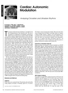
Fig. 1.
Transceiver architecture of TAG-SM.
As an example, by combining TDMA with SM for DLMU transmission, the data rate (bits/symbol) of the k-th user (1 ≤ k ≤ K) could be represented as ) 1( log2 (Nt ) + log2 (M ) , ROMA-SM,k = (2) K where log2 (Nt ) denotes the information bits conveyed by the activated TA index (here we assume only one TA is activated at any time slot), M = |X | denotes the number of symbols in an APM diagram X , such as phase shift keying (PSK) or quadrature amplitude modulation (QAM) and coefficient 1 K denotes that exclusive time-frequency resource is equally allocated to K users without inter-user interference. Although OMA-SM schemes enjoy free of inter-user interference, they suffer from spectral efficiency loss due to their inherent exclusive time-frequency resource allocation. When considering TDMA combined with SM, only one RF chain is required at the BS and hence the hardware cost of MU scenario is almost the same as the single-user (SU) scenario. B. TAG-SM for DL-MU Transmission Different from OMA-SM where exclusive time-frequency resource is allocated for various users, TAG-SM regards TAs at the BS as resource in spatial dimension to be allocated to different users [18]–[20]. As shown in Fig. 1, Nt TAs at the BS could be directly divided into K subgroups [18] (assuming Nt K is an integer for simplicity), e.g., the k-th TA subgroup serving the k-th user consists of TAs with indices in the range Nt t [(k − 1) N K + 1, k K ]. Hence, for the k-th user, only channel (k) Nt t vectors hj , (k − 1) N K + 1 ≤ j ≤ k K are valid to transmit the APM symbol. For DL bit stream of the k-th user, a random sequence of in(k) (k) dependent bits b(k) = [b1 b2 · · · ] enters the serial/parallel (S/P) converter and outputs two bit streams for TA selection and APM selection as shown in Fig. 1. After SM mapper, the signal vector for the k-th TA subgroup (the k-th user’s data) could be represented as √ [ ]T Nt ρ (k) 0 · · · 0 smk 0 · · · 0 ∈ C K ×1 , (3) xjk ,mk , K ↑ jk -th position t where 1 ≤ jk ≤ N K denotes TA subgroup, smk (1 ≤ mk
the selected TA index in the k-th ≤ M ) denotes the mk -th symbol
from the M -ary APM constellation diagram with E{s∗i si } = 1 and ρ denotes the total transmit power for all K users. Hence, the data rate (bits/symbol) of the k-th user in TAG-SM could be represented as RTAG-SM,k = log2
( Nt ) + log2 (M ). K
(4)
By adopting the same APM order, the data rate of TAG-SM is higher than OMA-SM, but at the cost of severe inter-user interference. Through the wireless channel H(k) , the received signal at the k-th user is given by [ ]T (1) (K) y(k) = H(k) (xj1 ,m1 )T · · · (xjK ,mK )T + n(k) √ ∑ (k) ) ρ ( (k) = h h smk + sml + n(k) , Nt Nt (l−1) (k−1) +j +j k l K K K l̸=k
(5) where
∑ l̸=k
(k) s ml N (l−1) Kt +jl
h
denotes the inter-user interfer(k)
(k)
(k)
ence caused by other users and n(k) = [n1 n2 · · · nNr ]T denotes the Nr -dimensional additive white Gaussian noise (k) (AWGN) with i.i.d. entries as ni ∼ CN (0, σn2 ). From Eq. (5), the effect of AWGN n(k) could be reduced by increasing the total transmit power ρ, while the inter-user ∑ (k) interference l̸=k h sml becomes the performance N (l−1) Kt +jl bottleneck. Hence, without inter-user interference cancellation, there exists an error floor in data detection at user side. Adaptive TA selection and precoding have been proposed to suppress this inter-user interference [18]–[20], but CSI is required at the BS which introduces additional training overhead. Moreover, compared to OMA-SM which only requires one RF chain, K RF chains are needed at the transmitter when TAGSM is deployed. III. P ROPOSED NOMA-SM To improve spectral efficiency and mitigate inter-user interference at the same time, we combine NOMA with SM for DL-MU transmission. In this section, transmitter and receiver of NOMA-SM as well as performance comparison with OMASM and TAG-SM are presented in detail.
2169-3536 (c) 2016 IEEE. Translations and content mining are permitted for academic research only. Personal use is also permitted, but republication/redistribution requires IEEE permission. See http://www.ieee.org/publications_standards/publications/rights/index.html for more information.
This article has been accepted for publication in a future issue of this journal, but has not been fully edited. Content may change prior to final publication. Citation information: DOI 10.1109/ACCESS.2017.2688019, IEEE Access 4
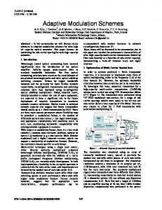
Fig. 2.
Transceiver architecture of the proposed NOMA-SM.
A. NOMA-SM Transmitter The transceiver architecture of NOMA-SM is illustrated in Fig. 2. Different from TAG-SM which divides TAs into subgroups to serve each user independently, all users in NOMA-SM share Nt TAs at the BS for DL transmission with carefully designed power allocation. Specifically, for the kth user, the signal vector transmitted over Nt TAs could be represented as √ (k) ˜ jk ,mk , ρk [0 · · · 0 smk 0 · · · 0]T ∈ CNt ×1 , x (6) ↑ jk -th position
where 1 ≤ jk ≤ Nt denotes the selected TA index among Nt TAs, smk (1 ≤ mk ≤ M ) denotes the mk -th symbol from the M -ary APM constellations and ρk denotes the transmit power ∑K allocated to the k-th user with the total power constraint ∗ k=1 ρk = ρ. PSK modulation is applied and we have si si = 1, 1 ≤ i ≤ M . The data rate of the k-th user in the proposed NOMA-SM could be represented as RNOMA-SM,k = log2 (Nt ) + log2 (M ).
(7)
Compared with OMA-SM and TAG-SM as shown in Eq. (2) and (4), the data rate of the proposed NOMA-SM could be improved significantly. B. NOMA-SM Receiver In OMA-SM and TAG-SM, the conventional SM detector in SU scenario could be directly deployed in DL-MU transmission. However, as shown in Fig. 2, a complicated SIC procedure has to be deployed at user side in NOMA-SM to mitigate inter-user interference before data detection, which leads to increased computational complexity. The received DL signal at the k-th user in NOMA-SM could be represented as ∑K (l) ˜ (k) = H(k) ˜ y x + n(k) l=1 jl ,ml ∑ √ √ (k) (k) = ρk hjk smk + ρl hjl sml + n(k) . (8) l̸=k
Since the signal received at the k-th user is disturbed by ∑ √ (k) other users’ data l̸=k ρl hjl sml , SIC procedure has to be combined with NOMA-SM at user side to mitigate inter-user interference [23], [24]. The basic idea of SIC is to remove
the data intended for other users with larger transmit power. Without loss of generality, power allocation is designed in a descending order with total power constraint as ρ1 > ρ2 > · · · > ρK ,
K ∑
ρk = ρ.
(9)
k=1
Since the 1st user has the highest transmit power, the SIC procedure is unnecessary and its data could be directly detected by the conventional SM based detection methods, e.g., maximum likelihood (ML) [12] √ (1) (10) [ˆj1 , m ˆ 1 ] = arg max∥˜ y(1) − ρ1 hj sm ∥22 , j,m
where [ˆj1 , m ˆ 1 ] denotes the detected data at the 1st user side. However, for the k-th user (k > 1), data detection becomes much more complicated compared to the 1st user since it has to remove the interference from the previous k − 1 users in a sequential way [23], [24]. After that, the updated received signal at the k-th user could be represented as ∑k−1 √ (k) (k) ˜ k−1 = y ˜ (k) − y pl hˆj sm (11) ˆ l,k , l=1
l,k
ˆ l,k ] with 1 ≤ l ≤ k − 1 denotes the detected where [ˆjl,k , m data of the l-th user, which should be removed at the k-th user. After the SIC procedure as shown in Eq. (11), the k-th user is able to detect its own data as √ (k) (k) [ˆjk , m ˆ k ] = arg max∥˜ yk−1 − ρk hj sm ∥22 . (12) j,m
Moreover, similar detection procedure could be easily obtained by deploying other detection algorithms, e.g., maximum ratio combining (MRC) [12], vector based detection (VBD) [28] and so on. C. Comparison of OMA-SM, TAG-SM and NOMA-SM As shown in Table I, we compare the proposed NOMA-SM with OMA-SM and TAG-SM in detail as follows. • Spectral efficiency: The data rate of OMA-SM is much lower than TAG-SM and NOMA-SM due to exclusive time-frequency resource allocation. Compared with TAG-SM, NOMA-SM enjoys an additional data rate as RNOMA-SM,k −RTAG-SM,k = log2 (K), since all users could utilize Nt TAs for DL transmission.
2169-3536 (c) 2016 IEEE. Translations and content mining are permitted for academic research only. Personal use is also permitted, but republication/redistribution requires IEEE permission. See http://www.ieee.org/publications_standards/publications/rights/index.html for more information.
This article has been accepted for publication in a future issue of this journal, but has not been fully edited. Content may change prior to final publication. Citation information: DOI 10.1109/ACCESS.2017.2688019, IEEE Access 5
TABLE I C OMPARISON FROM SYSTEM ASPECTS
Spectral efficiency Inter-user interference Encoder/decoder complexity
OMA-SM Low No Low
TAG-SM Middle Severe Middle
NOMA-SM High Acceptable High
Inter-user Interference: By allocating exclusive timefrequency resource to different users, OMA-SM almost has no inter-user interference. While in TAG-SM, interuser interference mitigation schemes have to be deployed at the BS side [18]–[20], where CSI requirement leads to additional training overhead. For NOMA-SM, the interuser interference could be mitigated at user side by deploying SIC procedure, the computational complexity is increased by K times at most compared with OMA-SM and TAG-SM. • Encoder/decoder complexity: Considering TDMA with OMA-SM, only one RF chain is required to support MUDL transmission. However, both TAG-SM and NOMASM require K RF chains at the transmitter to support K data streams simultaneously. Moreover, NOMA-SM also requires power allocation module at the BS and SIC module at user side. As a whole, NOMA-SM is able to achieve a better tradeoff between data rate and interference mitigation in DLMU transmission with the sacrifice of moderately increased computational complexity and hardware complexity. •
IV. P ERFORMANCE A NALYSIS AND P RACTICAL C ONSIDERATIONS In this section, performance analysis and practical considerations for NOMA-SM are presented, including SER analysis, low-complexity power allocation and user pairing for practical implementation. A. SER Analysis Based on Eq. (8), the equivalent interference to the 1st user could be represented as ∑K √ (1) I(1) = ρl hjl sml + n(1) , (13)
Various approximate expressions and bounds could be found about this function fSER ( σρ2 ) [12]–[14]. Hence, the SER of the n 1st user in NOMA-SM could be approximated as ( ) (a) ρ1 SERNOMA-SM,1 ≈ fSER ∑K , (15) 2 l=2 ρl + σn (a) √ (1) where ≈ denotes that I(1) is not independent of ρ1 hj1 sm1 (TA selected by the 1st user could also be selected by the latter users). After that, by considering SIC based ML detector at the k-th user, we have the following corollary about the SER approximation of the k-th user.
Corollary 1 The SER of the k-th user with SIC based ML detector in NOMA-SM transmission could be approximated at high SNR region as ∑k ( ) ρl SERNOMA-SM,k ≈ fSER ∑K . (16) 2 l=1 t=l+1 ρt + σn Proof : Firstly, the SER of the k-th user is divided into two parts as shown in Eq. (17). The first part Pk,1 denotes the SER when SIC procedure is correctly carried out, while the second part Pk,2 denotes the SER when any errors occur in SIC procedure. Pk,1 is directly approximated by the SIC (b)
failure probability in Eq. (18), where ≈ indicates that the tiny probability that the k-th user correctly detects its data when (c)
errors occur in the SIC procedure is ignored. After that, ≈ indicates ( the quadratic terms and ) high-order terms of fSER ∏k−1 that in l=1 1 − fSER ( ∑K ρlρ +σ2 ) could be ignored when n t=l+1 t fSER approaches to zero at high SNR region. Similar to Pk,1 , Pk,2 could also be approximated by fSER function as shown in Eq. (19). Finally, the SER of the k-th user with SIC based ML detector in NOMA-SM could be approximated by Eq. (16) at high SNR region. Based on Corollary 1, the detection error of the previous users will be propagated to the latter users. Hence, the latter users in NOMA-SM suffer from error propagation, which is unavoidable due to the SIC procedure. For practical implementation, the number of users in NOMA-SM should be kept small to avoid performance degradation caused by error propagation, e.g., typically K = 2 users.
l=2
(1) hjl
(1) [h1,jl
(1) h2,jl
(1)
(1)
where = · · · hNr ,jl ]T , hi,jl ∼ CN (0, 1), (1) (1) (1) |sml | = 1, 1 ≤ jl ≤ Nt and n(1) = [n1 n2 · · · nNr ]T (1) with ni ∼ CN (0, σn2 ). Hence, the element in the equivalent interference vector I(1) to the 1st user has the following i.i.d. distribution ∑K (1) Ii ∼ CN (0, ρl + σn2 ), (14) l=2
(1) Ii , 1
where ≤ i ≤ Nr denotes the i-th element in I(1) . The symbol error rate (SER) and bit error rate (BER) for classical SM in SU scenario have been widely studied [12]– [14]. Here a function fSER is defined to represent the SER of a point-to-point M -ary PSK based SM transmission with a Nt × Nr Rayleigh fading channel as fSER ( σρ2 ), where σρ2 n n denotes the average signal-to-noise-ratio (SNR) at the RAs.
B. Low-Complexity Power Allocation For practical implementation, power allocation should be carefully designed to achieve performance balance among all K users. By considering different optimization targets, we could formulate different problems, e.g., minimize the maximal SER of K users, minimize the average SER of all K users and so on. Firstly, we formulate the optimization problem P1 to minimize the maximal SER of K users as { } { } P1 : ρopt,1 = arg min max SERNOMA-SM,k : 1 ≤ k ≤ K k {ρk }
s.t. ρ1 > ρ2 > · · · > ρK ,
∑K k=1
ρk = ρ.
(20)
According to Corollary 1, the SER of the K-th user tends to be much higher than the previous K − 1 users. Hence, the
2169-3536 (c) 2016 IEEE. Translations and content mining are permitted for academic research only. Personal use is also permitted, but republication/redistribution requires IEEE permission. See http://www.ieee.org/publications_standards/publications/rights/index.html for more information.
This article has been accepted for publication in a future issue of this journal, but has not been fully edited. Content may change prior to final publication. Citation information: DOI 10.1109/ACCESS.2017.2688019, IEEE Access 6
( ) SERNOMA-SM,k =Pk,1 [ˆjk , m ˆ k ] ̸= [jk , mk ], ∃1 ≤ l ≤ k − 1, s.t., [ˆjl,k , m ˆ l,k ] ̸= [jl , ml ] ( ) +Pk,2 [ˆjk , m ˆ k ] ̸= [jk , mk ], [ˆjl,k , m ˆ l,k ] = [jl , ml ], ∀1 ≤ l ≤ k − 1 . ∏k−1 ( ( ) (a) ( (b) Pk,1 ≈ 1 − P [ˆjl,k , m ˆ l,k ] = [jt , mt ], ∀1 ≤ l ≤ k − 1 ≈ 1 − 1 − fSER ∑K l=1
( (c) ∑k−1 ≈ fSER ∑K l=1
)
ρl
t=l+1
ρt +
( (a) Pk,2 ≈ fSER ∑K (b)
(
σn2
t=k+1
( ≈ fSER ∑K
σn2
ρt + σn2
ρk
(c)
t=k+1
))
ρt + σn2 (18)
)
ρt + ρk
≈ fSER ∑K
t=l+1
.
ρk
t=k+1
ρl
(17)
( ) ∗ P [ˆjl,k , m ˆ l,k ] = [jt , mt ], ∀1 ≤ l ≤ k − 1
∑k−1 ) ( ( ∗ 1− fSER ∑K l=1
)
ρt + σn2
ρl
t=l+1
))
ρt + σn2
.
(19)
( ) 1 ∑K 1 ∑K ∑k ρl SERNOMA-SM,k ≈ fSER ∑K 2 k=1 k=1 l=1 K K t=l+1 ρt + σn ( ) ( ) ( ρK ) 1 ρ1 K −1 ρ2 ≈ fSER ∑K + fSER ∑K + · · · + fSER 2 . 2 2 K K σn t=2 ρt + σn t=3 ρt + σn
SER =
optimization problem P1 to minimize the maximal SER of K users could be approximated by minimizing the SER of the K-th user as { ′} P1′ : ρopt,1 = arg min SERNOMA-SM,K k {ρk }
≈ arg min {ρk }
∑K
( fSER ∑K l=1
ρl
t=l+1
ρt + σn2
) , (21)
where the power constraint is omitted here for simplicity. By assuming the prior knowledge of function fSER [12]–[14] and a small number of users, e.g., K = 2, the problem P1′ could be easily solved by the derivation of ρ1 (ρ2 = ρ − ρ1 ) or grid search [29]. Secondly, to minimize the average SER of all K users, the power allocation problem could be formulated as { } P2 : ρopt,2 = arg min SER k {ρk }
s.t. ρ1 > ρ2 > · · · > ρK ,
∑K k=1
ρk = ρ,
(22)
where detailed expression of SER is presented in Eq. (23). Similar to P1′ , P2 could also be solved with a small number of users [23]–[25], e.g., K = 2, 3. For practical implementation, a low-complexity power allocation scheme is proposed to provide numerical solutions to P1′ and P2 . •
Power division: The total power ρ is uniformly divided into N parts, and the power allocation ρk is constrained to be an integral multiple of Nρ , i.e., ρk = Tk Nρ (Tk is assumed to be an integer).
•
•
(23)
Power allocation patterns: The original power allocation constraints ∑K could be reformulated as T1 > T2 > · · · > TK , k=1 Tk = N . Since Tk should be an integer, the number of power allocation patterns is finite, and we could traverse all possible patterns with a small number of users, e.g., K = 2, 3. Numerical solution: By calculate the optimization functions in Eq. (21) and (22) of all possible power allocation patterns, we could obtain the numerical solutions to P1′ and P2 .
For instance, by considering P1′ with K = 2, the total power ρ is divided into N = 200 parts with each one Nρ . By applying the constraints of Tk , we could obtain all N2 − 1 possible power allocation patterns, i.e., T1 = N2 + 1, N2 + 2, · · · , N and T2 = N − T1 . The optimization function could be simplified 1 as f1′ (ρ1 ) = fSER ( ρ−ρρ11+σ2 ) + fSER ( ρ−ρ 2 ). Assuming that the σn n ∗ numerical result fSER is known (closed-form solution of fSER is not available in literature [12]–[14]). Afterward, we calculate the optimization function f1′ (ρ1 ) for all N2 − 1 possible power allocation patterns, and the optimum one with the lowest value of f1′ will be selected as the final power allocation result. C. User Pairing Different from the conventional NOMA to maximize the achievable rate of paired users regardless of the modulation issue [25]–[27], minimizing the SER of paired users is selected as the target in the proposed NOMA-SM. Hence, the results in conventional NOMA that users with more distinctive channel conditions are preferred to be paired could not be directly applied in the proposed NOMA-SM [27].
2169-3536 (c) 2016 IEEE. Translations and content mining are permitted for academic research only. Personal use is also permitted, but republication/redistribution requires IEEE permission. See http://www.ieee.org/publications_standards/publications/rights/index.html for more information.
This article has been accepted for publication in a future issue of this journal, but has not been fully edited. Content may change prior to final publication. Citation information: DOI 10.1109/ACCESS.2017.2688019, IEEE Access 7
where βk , 1 ≤ k ≤ K denote the large-scale fading coefficients of the k-th users [23]. Without loss of generality, we assume β1 ≤ · · · βk · · · ≤ βK . Hence, for the k-th user with power allocation ρk , its equivalent power allocation could be regarded as βk ρk . A simple yet efficient method is to pair users with equivalent power allocation approaching the optimization results obtained through the proposed lowcomplexity power allocation scheme. Specifically, for the k1 th user, the following principle could be applied to select its best pairing user as { } ρ′1 βk ρ∗1 ρ′1 βk1 ρ∗1 k2 = arg min min − ′ , − ′ , (25) βk ρ∗2 ρ2 βk1 ρ∗2 ρ2 k̸=k1 where {k1∗ , k2∗ } denotes the selected two pairing users among total K users and {ρ′1 , ρ′2 } denotes the numerical results provided by the proposed low-complexity power allocation scheme. Hence, with fixed power allocation, users with equivalent power allocation approaching the optimization results could be paired to achieve better SER performance balance in NOMA-SM. V. S IMULATION R ESULTS In this section, Monte Carlo based simulation results are presented to compare the performance of OMA-SM, TAG-SM and the proposed NOMA-SM. For most cases, i.i.d. Rayleigh fading channel is considered, while the near-far effect is added in user pairing discussion for NOMA-SM. Firstly, the error propagation in NOMA-SM is presented to verify the SER analysis (Corollary 1). Afterwards, the proposed lowcomplexity power allocation is compared to the simulation results. Then, the BER performance of OMA-SM, TAG-SM and the proposed NOMA-SM with low-complexity power allocation is compared in detail. Finally, the performance of user pairing method based on Eq. (25) is verified. A. Error Propagation Fig. 3 presents the error propagation by both theoretical analysis and numerical simulation with K = 2, Nt = Nr = 4, QPSK and i.i.d. Rayleigh fading channel. Since the closedform solution of fSER is not available in literature [12]–[14], ∗ the numerical result fSER (a point-to-point QPSK based SM transmission with a 4 × 4 i.i.d. Rayleigh fading channel) in region σρ2 ∈ [−30, 30] dB is firstly acquired through n numerical simulation. Specifically, the region [−30, 30] dB is sampled by 600 points (sample interval is 0.1 dB) and the SER performance among [−30, 30] dB could be calculated by linear interpolation based on these 600 sampled points. By assuming the same receiving SNR of the two users after ρ2 1 SIC procedure, i.e., ρ2ρ+σ 2 = σ 2 , the power allocation could n
n
0
10
−1
10
−2
10 SER
Due to the hardware cost of power amplifiers (PAs), fixed power allocation coefficients are usually deployed at the transmitter side [26]. In two user pairing case, we assume that the fixed power allocation coefficients are ρ∗1 = αρ, ρ∗2 = (1 − α)ρ. By considering the near-far effect from user distribution, the channel matrix of the k-th user is redefined as √ (24) G(k) = βk H(k) ,
−3
10
1st user, Theoretical results from Eq. (15) 2nd user, Theoretical results from Eq. (16) 1st user, Simulation results 2nd uesr, Simulation results
−4
10
−5
10
5
10
15
20
25
30
ρ/σ2n (dB)
Fig. 3. Error propagation among users in NOMA-SM with K = 2, Nt = Nr = 4, QPSK and RNOMA-SM,k = 4 bits/symbol.
√ be calculated as ρ2 = σn4 + σn2 ρ − σn2 , ρ1 = ρ − ρ2 . With ∗ , the theoretical SER performance of the numerical result fSER the 1st user and the 2nd user could be easily obtained through Eq. (15) and Eq. (16), which is presented in Fig. 3 by red and blue lines, respectively. Meanwhile, the SER performance of these two users by numerical simulation is also presented in Fig. 3 by red circle and blue diamond, respectively. The theoretical results anastomose with the simulation results well, which could be utilized to guide the design of power allocation and user pairing. From Fig. 3, the SER performance of the 2nd user is always worse than the 1st user due to the error propagation in SIC procedure as shown in Corollary 1. Hence, similar to the conventional NOMA [23], [24], error propagation also leads performance degradation in the latter users in the proposed NOMA-SM, which indicates that the number of multiplexing users should be small, e.g., typically K = 2. B. Power Allocation Fig. 4 shows the power allocation results obtained through the proposed low-complexity scheme and the numerical simulation with K = 2, Nt = Nr = 4, QPSK and RNOMA-SM,k = 4 bits/symbol. Two different optimization targets are considered, i.e., P1 to minimize the maximal SER of two users and P2 to minimize the average SER. The total power ρ is uniformly divided into N = 200 parts, and the one with the lowest SER among all possible patterns will be selected as the final power allocation result. For numerical simulation method, the SER performance of each sample point has to be acquired based on a large number of channel realization (at least 106 ), which is drawn in Fig. 4 by red circle and blue diamond for P1 and P2 , respectively. Due to the unacceptable computational complexity, simulation based power allocation could not be deployed in practical NOMA-SM. While, in the proposed low-complexity power allocation scheme, based on the SER ∗ analysis and the numerical result fSER , the target function could be directly calculated from Eq. (21) and Eq. (22) and the sample point with the lowest SER will be selected. Compared
2169-3536 (c) 2016 IEEE. Translations and content mining are permitted for academic research only. Personal use is also permitted, but republication/redistribution requires IEEE permission. See http://www.ieee.org/publications_standards/publications/rights/index.html for more information.
This article has been accepted for publication in a future issue of this journal, but has not been fully edited. Content may change prior to final publication. Citation information: DOI 10.1109/ACCESS.2017.2688019, IEEE Access 8
0
10
1
0.95 −1
10
Average BER
0.9
ρ1/ρ
0.85
0.8
OMA−SM,16PSK,Rk=3
−3
10
TAG−SM,QPSK,Rk=3 NOMA−SM,BPSK,Rk=3
P1, Proposed low−complexity power allocation
0.75
P2, Proposed low−complexity power allocation 0.7
0.65
−2
10
5
10
OMA−SM,64PSK,Rk=4
−4
10
P1, Simulation results
TAG−SM,8PSK,Rk=4
P2, Simulation results
NOMA−SM,QPSK,Rk=4
15
20
25
30
0
5
10
Fig. 4. Power allocation for NOMA-SM with K = 2, Nt = Nr = 4, QPSK and RNOMA-SM,k = 4 bits/symbol.
1
0.8
k
ρ /ρ
20
25
30
Fig. 6. BER performance comparison of OMA-SM, TAG-SM and NOMASM against σρ2 with K = 2, Nt = Nr = 4 and Rk = 3, 4 bits/symbol. n
C. Performance Comparison
0.9
0.7
P1, 1st user, ρ1/ρ
0.6
P , 2nd user, ρ /ρ 1
2
P , 3rd user, ρ /ρ 1
0.5
3
P , 1st user, ρ /ρ 2
1
0.4
P2, 2nd user, ρ2/ρ
0.3
P2, 3rd user, ρ3/ρ
0.2 0.1 0 10
15 ρ/σ2n (dB)
ρ/σ2n (dB)
15
20
25
30
35
40
ρ/σ2 (dB) n
Fig. 5. The proposed low-complexity power allocation result for NOMA-SM with K = 3, Nt = Nr = 4, QPSK and RNOMA-SM,k = 4 bits/symbol.
with simulation based power allocation, the computational complexity of the proposed scheme is almost negligible. From Fig. 4, the power allocation results of numerical simulation method and our proposal are similar and overlapped in high SNR region. Hence, the proposed low-complexity power allocation could be deployed to achieve the trade-off between computational complexity and system performance. Fig. 5 presents the proposed low-complexity power allocation result for NOMA-SM with K = 3, Nt = Nr = 4, QPSK, and RNOMA-SM,k = 4 bits/symbol. For this K = 3 user multiplexing case, the total power is divided in a finer way with N = 500. All possible power allocation∑patterns {T1 , T2 , T3 } 3 meeting the constraints T1 > T2 > T3 , k=1 Tk = N will be traversed to calculate the optimization function, and the one with lowest value will be selected as the numerical results. As shown in Fig. 5, the low-complexity power allocation scheme could be also applied when the number of users is slightly increased, e.g., K = 3.
Fig. 6 compares the average BER performance of OMASM, TAG-SM and the proposed NOMA-SM against the average receiving SNR σρ2 with K = 2, Nt = Nr = 4 n and Rk = 3, 4 bits/symbol. For OMA-SM with Rk = 3 bits/symbol, M = 2KRk −log2 (Nt ) (16PSK) has to be applied and the BER performance (black triangle line in Fig. 6) is better than TAG-SM and NOMA-SM (blue square line and red circle line in Fig. 6). However, by increasing Rk from 3 to 4 bits/symbol, much higher order PSK, i.e., 64PSK, has to be applied in OMA-SM, which leads to severe performance degradation (black triangle dashed line in Fig. 6). Hence, the most disadvantage of OMA-SM is the data rate limitation as shown in Eq. (2), which is caused by exclusive time-frequency resource allocation. For TAG-SM, the BER performance is acceptable at low SNR region, i.e., σρ2 < 5 dB. By increasing n the SNR σρ2 , the BER performance of TAG-SM could not n be improved due to the inter-user interference, which further leads to an error floor. According to [18]–[20], precoding and adaptive TA selection schemes could be adopted to improve the BER performance of TAG-SM, but at the cost of additional overhead to obtain CSI at the transmitter. For the proposed NOMA-SM, the low-complexity power allocation scheme is applied together. From Fig. 6 with Rk = 3 bits/symbol, similar BER performance of NOMA-SM with OMA-SM could be achieved. However, by increasing Rk from 3 to 4 bits/symbol, NOMA-SM only needs to replace BPSK by QPSK and the degradation of BER performance is quite little (two red circle lines in Fig. 6), which is much lower than both OMA-SM and TAG-SM. Fig. 7 compares the average BER performance of OMASM, TAG-SM and the proposed NOMA-SM against the RA number Nr with K = 2, Nt = 4 and Rk = 3, 4 bits/symbol. By considering Rk = 3 bits/symbol, similar BER performance of OMA-SM and NOMA-SM could be observed (Nr = 8 to achieve BER = 10−4 ) and could be significantly improved by increasing the RA number Nr . Meanwhile, a much larger
2169-3536 (c) 2016 IEEE. Translations and content mining are permitted for academic research only. Personal use is also permitted, but republication/redistribution requires IEEE permission. See http://www.ieee.org/publications_standards/publications/rights/index.html for more information.
This article has been accepted for publication in a future issue of this journal, but has not been fully edited. Content may change prior to final publication. Citation information: DOI 10.1109/ACCESS.2017.2688019, IEEE Access 9
best pairing user with the lowest BER performance from the rest 9 users for NOMA-SM. Two cases of fixed power allocation are considered, i.e., ρ∗1 = 0.6ρ, ρ∗2 = 0.4ρ and ρ∗1 = 0.8ρ, ρ∗2 = 0.2ρ. Based on exhaustive search among the rest 9 users, the best pairing user for the 1st user is plotted by dashed lines as shown in Fig. 8. Based on Eq. (25), the pairing user for the 1st user could be selected with low complexity to approach the power allocation result obtained from P2 . The user pairing results based on Eq. (25) is plotted in Fig. 8 by solid lines, which is almost the same as the exhaustive search result.
0
10
−1
Average BER
10
−2
10
OMA−SM,16PSK,Rk=3
−3
10
TAG−SM,QPSK,Rk=3 NOMA−SM,BPSK,Rk=3 OMA−SM,64PSK,Rk=4
−4
10
TAG−SM,8PSK,Rk=4
VI. C ONCLUSIONS
NOMA−SM,QPSK,Rk=4 0
5
10
15
20
25
30
35
Nr
Fig. 7. BER performance comparison of OMA-SM, TAG-SM and NOMASM against Nr with K = 2, Nt = 4 and Rk = 3, 4 bits/symbol.
10 9 8 7
k2
6 5 ρ* =0.6ρ, ρ* =0.4ρ, Selection by Eq. (25)
4
1 * 1 * ρ1=0.8ρ, * ρ1=0.8ρ,
2 1
2 * 2 * ρ2=0.2ρ, * ρ2=0.2ρ,
ρ =0.6ρ, ρ =0.4ρ, Exhaustive search
3
5
10
15
20
R EFERENCES
Selection by Eq. (25) Exhaustive search 25
30
ρ/σ2n (dB)
Fig. 8.
When SM is employed in DL-MU transmission scenarios, OMA-SM suffers from low spectral efficiency, while TAGSM suffers from severe inter-user interference. In this paper, by cooperating NOMA with SM, NOMA-SM has been proposed to achieve a trade-off between spectral efficiency and interference mitigation. By deploying SIC detection at user side, inter-user interference could be effectively eliminated with the sacrifice of error propagation among users. SER approximation in NOMA-SM is derived and a low-complexity power allocation is proposed. Moreover, when near-far effect from user distribution is considered, user pairing for NOMASM is also addressed. The performance of OMA-SM, TAGSM and the proposed NOMA-SM is compared by simulations and the effectiveness of the proposed low-complexity power allocation and user pairing is verified.
User pairing for NOMA-SM with user number K = 10.
number of RAs is required for TAG-SM to achieve the same BER performance, i.e., Nr > 20 to achieve BER = 10−4 . By increasing Rk to 4 bits/symbol, similar BER performance of the proposed NOMA-SM could be obtained as that with Rk = 3 bits/symbol. For TAG-SM, there is a BER performance degradation when the transmit rate Rk is increased from 3 to 4 bits/symbol, while a much larger BER performance degradation could be found in OMA-SM. These is no error floor of TAG-SM in Fig. 7 since the increasing of Nr could always improve the detection performance. In general, compared to both OMA-SM and TAG-SM, the proposed NOMASM is able to achieve better BER performance against the RA number Nr . D. User Pairing Fig. 8 presents the user pairing result in NOMA-SM with user number K = 10. According to Eq. (24), we firstly set the large-scale fading coefficients [β1 β2 · · · β10 ] = [1 0.9 0.8 · · · 0.1]. For the 1st user, we aim to select its
[1] J. G. Andrews, S. Buzzi, W. Choi, S. V. Hanly, A. Lozano, A. C. Soong and J. C. Zhang, “What will 5G be?” IEEE J. Sel. Areas Commun., vol. 32, no. 6, pp. 1065-1082, Jun. 2014. [2] F. Boccardi, R. W. Heath, A. Lozano, T. L. Marzetta and P. Popovski, “Five disruptive technology directions for 5G,” IEEE Commun. Mag., vol. 52, no. 2, pp. 74-80, Feb. 2014. [3] A. Fehske, G. Fettweis, J. Malmodin and G. Biczok, “The global footprint of mobile communications: The ecological and economic perspective,” IEEE Commun. Mag., vol. 49, no. 8, pp. 55-62, Aug. 2011. [4] J. Liu, H. Guo, Z. M. Fadlullah and N. Kato, “Energy consumption minimization for FiWi enhanced LTE-A HetNets with UE connection constraint,” IEEE Commun. Mag., vol. 54, no. 11, pp. 56-62, Nov. 2016. [5] P. Frenger, P. Moberg, J. Malmodin, Y. Jading and I. Godor, “Reducing energy consumption in LTE with cell DTX,” IEEE Vehicular Technology Conference (VTC Spring), Yokohama, 2011, pp. 1-5. [6] P. Wolniansky, G. Foschini, G. Golden and R. Valenzuela, “V-blast: an architecture for realizing very high data rates over the rich-scattering wireless channel,” IEEE Signals, Systems, and Electronics, Pisa, 1998, pp. 295-300. [7] H. Jafarkhani, Space-Time Coding, Theory and Practive, Cambridge University Press, 2005. [8] J. Jeganathan, A. Ghrayeb, L. Szczecinski and A. Ceron, “Space shift keying modulation for MIMO channels,” IEEE Trans. Wireless Commun., vol. 8, no. 7, pp. 3692-3703, Jul. 2009. [9] R. Y. Mesleh, H. Haas, S. Sinanovic, A. W. Chang and S. Yun, “Spatial modulation,” IEEE Trans. Veh. Tech., vol. 57, no. 4, pp. 2228-2241, Jul. 2008. [10] M. D. Renzo, H. Haas and P. M. Grant, “Spatial modulation for multipleantenna wireless systems: a survey,” IEEE Commun. Mag., vol. 49, no. 12, pp. 182-191, Dec. 2011. [11] R. Mesleh, M. D. Renzo, H. Haas and P. M. Grant, “Trellis coded spatial modulation,” IEEE Trans. Wireless Commun., vol. 9, no. 7, pp. 23492361, Jul. 2010. [12] J. Jeganathan, A. Ghrayeb and L. Szczecinski, “Spatial modulation: optimal detection and performance analysis,” IEEE Commun. Lett., vol. 12, no. 8, pp. 545-547, Aug. 2008.
2169-3536 (c) 2016 IEEE. Translations and content mining are permitted for academic research only. Personal use is also permitted, but republication/redistribution requires IEEE permission. See http://www.ieee.org/publications_standards/publications/rights/index.html for more information.
This article has been accepted for publication in a future issue of this journal, but has not been fully edited. Content may change prior to final publication. Citation information: DOI 10.1109/ACCESS.2017.2688019, IEEE Access 10
[13] T. L. Narasimhan and A. Chockalingam, “On the capacity and performance of generalized spatial modulation,” IEEE Commun. Lett., vol. 20, no. 2, pp. 252-255, Feb. 2016. [14] M. D. Renzo and H. Haas, “Bit error probability of SM-MIMO over generalized fading channels,” IEEE Trans. Veh. Tech., vol. 61, no. 3, pp. 1124-1144, Mar. 2012. [15] T. L. Narasimhan, P. Raviteja and A. Chockalingam, “Generalized spatial modulation in large-scale multiuser MIMO systems,” IEEE Trans. Wireless Commun., vol. 14, no. 7, pp. 3764-3779, Jul. 2015. [16] S. Wang, Y. Li and J. Wang, “Multiuser detection in massive spatial modulation MIMO with low-resolution ADCs,” IEEE Trans. Wireless Commun., vol. 14, no. 4, pp. 2156-2168, Apr. 2015. [17] Z. Gao, L. Dai, Z. Wang, S. Chen and L. Hanzo, “Compressive-sensingbased multiuser detector for the large-scale SM-MIMO uplink,” IEEE Trans. Veh. Tech., vol. 65, no. 10, pp. 8725-8730, Oct. 2016. [18] X. Li, Y. Zhang, L. Xiao, X. Xu and J. Wang, “A novel precoding scheme for downlink multi-user spatial modulation system,” IEEE Personal, Indoor, and Mobile Radio Commun. (PIMRC), London, 2013, pp. 13611365. [19] S. Narayanan, M. J. Chaudhry, A. Stavridis, M. Di Renzo, F. Graziosi and H. Haas, “Multi-user spatial modulation MIMO,” IEEE Wireless Communications and Networking Conference (WCNC), Istanbul, 2014, pp. 671-676. [20] X. Wu, M. D. Renzo and H. Haas, “A novel multiple access scheme based on spatial modulation MIMO,” IEEE Computer Aided Modeling and Design of Communication Links and Networks (CAMAD), Athens, 2014, pp. 285-289. [21] X. Wu, M. D. Renzo and H. Haas, “Adaptive selection of antennas for optimum transmission in spatial modulation,” IEEE Trans. Wireless Commun., vol. 14, no. 7, pp. 3630-3641, Jul. 2015. [22] M. Maleki, H. R. Bahrami and A. Alizadeh, “Layered spatial modulation for multiuser communications,” IEEE Trans. Wireless Commun., vol. 15, no. 10, pp. 7143-7159, Oct. 2016. [23] Y. Saito, Y. Kishiyama, A. Benjebbour, T. Nakamura, A. Li and K. Higuchi, “Non-orthogonal multiple access (NOMA) for cellular future radio access,” IEEE Vehicular Technology Conference (VTC Spring), Dresden, 2013, pp. 1-5. [24] A. Benjebbour, Y. Saito, Y. Kishiyama, A. Li, A. Harada and T. Nakamura, “Concept and practical considerations of non-orthogonal multiple access (NOMA) for future radio access,” IEEE Intelligent Signal Processing and Communications Systems (ISPACS), Naha, 2013, pp. 770-774. [25] Z. Ding, Z. Yang, P. Fan and H. V. Poor, “On the performance of nonorthogonal multiple access in 5G systems with randomly deployed users,” IEEE Signal Process. Lett., vol. 21, no. 12, pp. 1501-1505, Dec. 2014. [26] S. Timotheou and I. Krikidis, “Fairness for non-orthogonal multiple access in 5G systems,” IEEE Signal Process. Lett., vol. 22, no. 10, pp. 1647-1651, Oct. 2015. [27] Z. Ding, P. Fan and H. V. Poor, “Impact of user pairing on 5G nonorthogonal multiple-access downlink transmissions,” IEEE Trans. Veh. Tech., vol. 65, no. 8, pp. 6010-6023, Aug. 2016. [28] J. Wang, S. Jia and J. Song, “Signal vector based detection scheme for spatial modulation,” IEEE Commun. Lett., vol. 16, no. 1, pp. 19-21, Jan. 2012. [29] J. Stoer and R. Bulirsch, Introduction to numerical analysis, Springer Science and Business Media, 2013.
Zhaocheng Wang (M09-SM11) received the B.S., M.S., and Ph.D. degrees from Tsinghua University, Beijing, China, in 1991, 1993, and 1996, respectively. From 1996 to 1997, he was a Postdoctoral Fellow with Nanyang Technological University, Singapore. From 1997 to 1999, he was with OKI Techno Centre (Singapore) Pte. Ltd., Singapore, where he was first a Research Engineer and later became a Senior Engineer. From 1999 to 2009, he was with Sony Deutschland GmbH, where he was first a Senior Engineer and later became a Principal Engineer. He is currently a Professor of Electronic Engineering with Tsinghua University and serves as the Director of Broadband Communication Key Laboratory, Tsinghua National Laboratory for Information Science and Technology (TNlist). He has authored or coauthored over 120 journal papers. He is the holder of 34 granted U.S./EU patents. He has coauthored two books, one of which, Millimeter Wave Communication Systems, was selected by IEEE Series on Digital and Mobile Communication (Wiley-IEEE Press). His research interests include wireless communications, visible light communications, millimeterwave communications, and digital broadcasting. He is a Fellow of the Institution of Engineering and Technology. He served as the Associate Editor of the IEEE Transactions on Wireless Communications (2011-2015) and the Associate Editor of the IEEE Communications Letters (2013-2016), and has also served as Technical Program Committee Co-Chair of various international conferences.
Jianfei Cao received the B.S. and Ph.D. degrees from Hunan University and Beijing Jiaotong University, China in 2006 and 2012, respectively. From 2009 to 2010, he studied as a visiting Ph.D. in the University of Southampton, U.K. From 2012 to 2014, he worked as an associated researcher in NEC Laboratory China. From 2014 to 2016, he worked as a senior engineer in Samsung Research Laboratory China. From 2016 to present, he worked as a vice manager in Sony China Research Laboratory. His research interests include FD-MIMO in LTE and Massive MIMO in 5G NR.
Xudong Zhu received his B.S. degree from the department of Electronic Engineering in Tsinghua University, Beijing, China, in 2012. He has been pursuing the Ph.D. degree at the Broadband Communication and Signal Processing Laboratory in Tsinghua University from 2012 to now. His main research interests are in the areas of MIMO technique and mobile communication, especially in spatial modulation, sparse signal reconstruction and massive MIMO.
2169-3536 (c) 2016 IEEE. Translations and content mining are permitted for academic research only. Personal use is also permitted, but republication/redistribution requires IEEE permission. See http://www.ieee.org/publications_standards/publications/rights/index.html for more information.