3/4G. Fig. 6. Average MPTCP Uplink Throughput according to Signal Strength. 0. 1. 2. 3. 4. 5. 6. -71~ .... (Samsung Galaxy S3 SGH-I747 for AT&T). The Linux ...
Cross-Layer Path Management in Multi-path Transport Protocol for Mobile Devices Yeon-sup Lim∗ , Yung-Chih Chen∗ , Erich M. Nahum†, Don Towsley∗, and Kang-Won Lee† ∗ School
of Computer Science, University of Massachusetts Amherst, MA, USA † IBM T.J. Watson Research Center, NY, USA
Abstract—MPTCP is a new transport protocol that enables mobile devices to use several physical paths simultaneously through multiple network interfaces, such as WiFi and cellular. However, wireless path characteristics change frequently in mobile environments, causing challenges for MPTCP: For example, WiFi associated paths often become unavailable as devices move, since WiFi has intermittent connectivity caused by the short signal range and susceptibility to interference. In this work, we improve MPTCP to manage path usage based on the associated link status. This variant, called MPTCP-MA, uses MAC-Layer information to locally estimate path quality and connectivity. By suspending/releasing paths based on their quality, MPTCP-MA can more effectively utilize restored paths. We have implemented and deployed MPTCP-MA in Linux and Android. Our experimental results show that MPTCP-MA can efficiently utilize an intermittently available path, with Wifi throughput improvements of up to 72 percent.
I.
I NTRODUCTION
The deployment of mobile devices such as smartphones and tablets has increased significantly over the last few years. This success is based on the rapid progress and ubiquity of wireless technologies, such as IEEE 802.11 (WiFi) and cellular (3G/4G) communication networks. The advent of mobile devices that have multiple wireless interfaces is leading to efforts to take advantage of these interfaces and utilize multiple paths simultaneously. Multi-path TCP (MPTCP) [8], [21] is a new transport protocol supporting path diversity to achieve both higher throughput and greater availability by extending standard TCP. To maximize the benefit of multiple paths, it is necessary for MPTCP to not only utilize all available paths, but to determine path availability and quality as quickly as possible. However, path quality frequently changes in mobile networks, particularly in the case of WiFi. WiFi connectivity is often intermittent in mobile scenarios due to the short signal ranges of access points (APs). However, MPTCP currently is unable to manage frequently broken/recovered paths, as it relies on the use of coarse-grained timeouts. This results in unnecessary delays after a path recovers, since the sender must wait until a successful retransmission occurs. This problem becomes more severe the longer a path is broken, as TCP’s course-grained retransmission timer increases exponentially. Our analysis and simulation measurements show that standard MPTCP can lose a significant fraction of available connection time as the disconnected duration increases. To improve standard single-path TCP performance over lossy wireless links, several approaches have been proposed [3], [9], [13], [14], [23]. These approaches control TCP behavior, such as the congestion window, by recognizing the cause c 2014 IEEE 978-1-4799-3360-0/14/$31.00 �
of packet losses and distinguishing losses caused by congestion from those caused by link failure, or by decoupling congestion control over the wired path from the wireless path. Common to many of these approaches is the notion of communicating the relevant information to the peer host, but since these are all single-path solutions, they rely on the same unreliable path to transmit this information, which is problematic. However, the path diversity of MPTCP provides an opportunity to overcome this limitation, by notifying the other end using a different path. The goal of this paper is to efficiently manage paths based on their connectivity status, in order to mitigate the delay of detecting and using restored paths in MPTCP. To this end, we propose MPTCP-MA, which controls path usage based on MAC-Layer information. MPTCP-MA exploits MAC-Layer information to estimate path status, and suspends/releases a path based on this estimation. By quickly detecting path failure and recovery, MPTCP-MA can avoid unnecessary losses and utilize recovered paths more quickly. We implement MPTCPMA in a Linux desktop and an Android smartphone, and perform experiments in a mobile environment. Our results show that MPTCP-MA more efficiently utilizes an intermittently available path than MPTCP, by improving WiFi throughput by up to 72 percent. The rest of this paper is organized as follows: We describe the problem scenario in more detail in Section II. In Section III, we explain our design and approach for MPTCP-MA. Experimental results are presented in Section IV. After reviewing related work in Section V, we conclude in Section VI. II.
P ROBLEM M OTIVATION
In this Section we show how the problem of under-utilized paths is fundamental based on the way TCP responds to loss. We briefly describe MPTCP and quantify the utilization problem by both modeling and execution-driven simulation. A. Multi-path TCP MPTCP is currently being standardized by IETF as a TCPcompatible protocol, transparent to user applications, that takes advantage of multiple paths through several communication interfaces [8]. MPTCP allows a single data stream to be split across multiple paths referred as to subflows: subflows are defined logically by all end-to-end interface pairs. For example, if each host has two interfaces, an MPTCP connection consists of four subflows. These subflows are exposed to the application layer as one standard TCP connection, so that a user application does not need to be modified to utilize MPTCP. In MPTCP, each subflow processes packets in the same manner as standard TCP, except for congestion control. MPTCP uses a coupled congestion control algorithm across all subflows to
2
guarantee TCP fairness at shared bottlenecks between standard TCP and MPTCP [24].
B. Broken Paths in MPTCP Standard TCP is unaware of whether a path is up or down: regardless of path status, a TCP sender retransmits lost packets and exponentially increases the retransmission timeout (RTO) for next retransmission when an acknowledgment does not arrive at the TCP sender within a RTO [18]. Similarly, MPTCP does not have a particular mechanism to manage path status changes. However, the current implementation [21] has an additional event handler to process address change events at a network interface: •
NETDEV_UP: This event occurs when an IP address is added to the interface. MPTCP then establishes the corresponding subflow associations.
•
NETDEV_DOWN: This event is notified when the interface loses an IP address. With this event, MPTCP terminates all corresponding subflow connections.
Unfortunately, mobile devices can lose or regain paths without either of these events occurring in a mobile scenario. For example, a WiFi connection in a mobile device often becomes unusable due to the device moving outside the range of an access point, even when its WiFi interface still maintains an IP address. In this paper, we consider a scenario where paths are still valid (i.e., the interfaces have valid IP addresses) but become unusable, e.g., a weak WiFi association that prevents communication but does not trigger an IP address change via a NETDEV_UP/DOWN event. C. Backup Mode in MPTCP MPTCP has three modes of operation to control subflow usage. One of them is backup mode, where MPTCP opens TCP subflows over all interfaces, but uses only a subset of them for packet transmission [17]. If a user sets a particular interface to backup mode, MPTCP avoids sending traffic through the corresponding subflows. Then, in order to force a remote-side to avoid using the subflows, MPTCP sends a MP_PRIO on these subflows to the remote-side. However, MPTCP does not have any mechanism to control the mode of a subflow based on its connectivity status. In addition, the handling procedure for MP_PRIO needs to be modified in order to deal with in-flight packets (i.e., packets which are not acknowledged yet) on the subflow that is to be placed in backup mode. D. Under-utilization of Recovered Paths In this subsection, we demonstrate the under-utilization problem that exists when a subflow recovers in MPTCP. For experiments, we use the Common Open Research Emulator (CORE) [1] that allows us to control a link connectivity status
Fig. 1.
Data Sequence
Since ordering is preserved within a subflow, but not across them, MPTCP must take care to combine subflows into the original ordered stream. MPTCP appends additional information called the data sequence number as a TCP header option to each packet. Based on the data sequence numbers, MPTCP merges multiple subflows properly and delivers inorder streams at the connection level.
Simple Topology for MPTCP 1.4e+09 1.38e+09 1.36e+09 1.34e+09 1.32e+09 1.3e+09 1.28e+09 1.26e+09 1.24e+09
Wait for next timeout
Link 1-3 is broken 0
10
20
30
40
50
60
70
80
90
Time (seconds) C1-S1
Fig. 2.
C1-S2
C2-S1
C2-S2
Re-use Delay of Active Subflow
in emulated networks, where each node runs a modified Linux kernel with MPTCP in the network protocol stack. Consider the simple topology shown in Figure 1, where nodes 1 and 4 have two interfaces each, and node 1 is transmitting data to node 4 through an MPTCP connection. Assume that link (1, 3) is a link that frequently breaks. Denote node 1’s interfaces as C1 and C2 and node 4’s interfaces as S1 and S2. In this case, MPTCP establishes four subflows denoted C1 − S1, C1 − S2, C2 − S1, and C2 − S2. Two subflows (C2−S1 and C2−S2) are affected by the status of link (1, 3). In the rest of this paper, we use the following terminology for a subflow status: active - available for transferring packets, and inactive - unusable for packet transmissions. Figure 2 shows the TCP data sequence numbers over time when link (1, 3) breaks at time 30 and recovers at time 60. The contributions of subflows C1−S1 and C1−S2 are obscured by those of other subflows even though packets are continuously transmitted through them. As can be seen by the change in slope from time 30 to time 75 in Figure 2, the throughput is lower when subflows C2 − S1 and C2 − S2 are not used. We observe retransmissions based on exponential timeouts on the two subflows associated with link (1, 3) (subflows C2 − S1 and C2 − S2) while the link is broken. Even though link (1, 3) recovers at time 60, the two subflows C2 − S1 and C2 − S2 are not used until their RTOs expire. Thus, MPTCP cannot utilize them for many seconds even though the subflows are active. This behavior is illustrated in Figure 3 and modeled by a simple two state discrete time Markov chain where the state indicates the subflow status as active and inactive. Assume that a packet transmission (data and ACK exchange) completes in one unit time and a node can perfectly measure RTTs. Denote the probability that a subflow becomes inactive by λi and the probability that a subflow becomes active by λa . The expected inactive and active durations after they start, E[Di ] and E[Da ], can be calculated as: ∞ � 1 k−1 E[Di ]
=
k(1 − λa )
k=1
E[Da ]
=
1 λi
λa =
λa
3
Timing Diagram of Retransmission
In this model we assume an RTT of one when a packet transmission is successful, and the RTO value for the nth timeout to be 2n . Suppose that one RTO occurs at the start of an inactive period. Then, the expected number of following RTOs until a subflow becomes active, E[N ], can be approximated as: � � E[N ]
≈
log 2
1 1 (E[Di ] + 1) = log2 2 2
1 +1 λa
Fraction of Unutilized Active Period (%)
Fig. 3.
Figure 5 presents the fraction of unutilized active period averaged over the two subflows C2 − S1 and C2 − S2 as a function of the inactive duration X. As shown in the figure, the subflows associated with link (1, 3) are unutilized as fraction of the inactive duration X increases: the case of 30 sec disconnection is an exception because link recovery time is close to a timeout expiration, compared to the case of 40 sec disconnection. We also observe that the experimental results accord closely to predictions made by the model in spite of the many assumptions. Based on both the experiments and the model, we see that a subflow is not efficiently utilized, as the inactive duration becomes longer than the active duration, since it has to wait for the next successful retransmission following a timeout.
The subflow can become active in the middle of an RTO. We approximate the average remaining duration of this RTO, E[R], as: 2E[N ]+1
E[R]
� �
�
E[N ]+1
2E[N]+1 − k (1 − λa )2
≈
−k
λa
k=0 1
=
1 − λa − (2 + λa )(1 − λa ) λa λa
+2
Thus, the fraction of unutilized active subflow period F , is approximated as: � � F
≈
min
=
min
E[R] , 1.0 E[Da ]
λi (1 − λa − (2 + λa )(1 − λa ) λa
1 λa
+2
)
, 1.0
Figure 4 presents F as a function of λi for different values of λa . As shown in Figure 4, the active period is less utilized as it becomes shorter, i.e., larger λi . With a particular expected length of active period, longer inactive period, i.e., smaller λa , results in lower utilization of active period. 1 0.8
λa=0.1 λa=0.3 λa=0.5 λa=0.7 λa=0.9
F
0.6 0.4 0.2 0
0
0.2
0.4
0.6
0.8
1
λi
Fig. 4.
F according to λi and λa
We perform further experiments using CORE to estimate what fraction of the unutilized active period as a function of the inactive duration. Assume that link (1, 3) in Figure 1 is connected for 30 seconds and then breaks for a time of duration X, after which it is again connected for another 30 seconds. While repeating this procedure ten times, we investigate the fraction of time during which subflows (C2 − S1 and C2 − S2) are unutilized even though they are active, i.e., link (1, 3) becomes connected.
Fig. 5.
100
Experiments Model
80 60 40 20 0
10 20 30 40 50 Inactive Subflow Duration (seconds)
Unutilized Active Subflow Period
III.
A PPROACH
In this section, we describe our approach to solving the problem of under-utilization of active subflows when those are restored from an inactive status, using MPTCP with MACLayer awareness, called MPTCP-MA, Using WiFi as an example, MPTCP-MA consists of a simple yet effective approach to estimate a subflow status using MAC-Layer information and corresponding subflow management to support efficient use of active subflows. A. Motivation The IEEE 802.11 standard defines receiver sensitivity, which is the minimum signal strength for a receiver to be able to acceptably decode frames [22]. Receiver sensitivity is governed by the underlying receiver noise floor, which is a measure of interference from all noise sources and unwanted signals: as the noise floor rises, a receiver sensitivity increases. Since it is difficult to measure the actual noise floor at a mobile device, we cannot determine the exact required receiver sensitivity. To find a method to determine the threshold of receiver sensitivity for estimating subflow status, we first investigate MAC-Layer behavior with MPTCP according to WiFi signal strength. To this end, we perform a set of experiments in a static scenario. After setting up an 802.11g access point at a fixed location, we locate a mobile device at varying distances from the AP as a way of controlling signal strength. Since the signal strength fluctuates over time, we choose the location for each signal strength range after measuring signal strength for one minute. Then, the mobile device uploads a 30 MB file to the server five times at each location.
4
Avg. Throughput (Mbps)
TABLE I. WiFi 3/4G
12 10
R(t) Rmin Ntx (t) Nretx (t) S(t)
8 6 4 2 0
-71~ -67~ -63~ -59~ -55~ WiFi Signal Range (dBm)
Average MPTCP Uplink Throughput according to Signal Strength 6 5 4 3 2 1 0
-71~
-67~
-63~
-59~
-55~
WiFi Signal Range (dBm)
(a) Ratio of Mac-Layer ReTx. to MAC-Layer Tx. Fig. 7.
Avg. MAC Data rate (Mbps)
Avg. Ratio of MAC ReTx. to Tx.
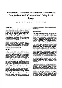
Fig. 6.
50
TI TA α β γ
N OTATIONS
Definition Measured PHY Data Rate at Unit Time t Lowest PHY Data Rate Number of Frame Transmissions at Unit Time t Number of Frame Retransmissions at Unit Time t Measured Signal Strength at Unit Time t Signal Strength below which WiFi subflow is labeled inactive Signal Strength above which WiFi subflow is labeled active Sensitivity Parameter Parameter to determine TA from TI Polling Interval to estimate path quality
40 30 20 10 0
-71~ -67~ -63~ -59~ -55~
data rate, if the WiFi link has poor quality. In the following subsection, we present a method for estimating WiFi subflow status inspired by these findings.
WiFi Signal Range (dBm)
(b) Average Tx. Data Rate
MAC-Layer Behavior according to Signal Strength
Figure 6 presents the average MPTCP throughput according to the measured signal strength. As shown in Figure 6, MPTCP throughput over WiFi decreases as the WiFi signal strength becomes weaker: in particular, WiFi throughput is almost zero when the signal strength falls below -71 dBm. We see that -71 dBm is the receiver sensitivity which can be used as a signal strength threshold to determine when a WiFi subflow becomes inactive. However, this threshold can vary due to environmental factors such as underlying noise, thus, we need an adaptive method to determine a proper estimate. We investigated MAC-Layer frame transmission in the experiments and observe that MPTCP still directs packets to WiFi even when the signal strength falls below -71 dBm, but the MAC-Layer frequently fails to deliver them to the AP after multiple frame transmission retries. Figure 7(a) shows the ratio of the number of MAC-Layer frame retransmissions to the number of transmissions versus signal strength. Throughput decreases, and the MAC layer performs more retransmissions than transmissions, as the signal strength becomes weaker. In particular, the WiFi throughput approaches zero when the retransmission ratio is larger than one. This indicates that the ratio of frame retransmissions can be used to to determine the WiFi signal strength threshold for the subflow status estimation. Rate adaptation is one of the basic functionalities in IEEE 802.11, which is designed to cope with the variation of wireless channels by exploiting the multi-rate capability provided by the 802.11 physical layer (PHY) [5]. Figure 7(b) presents the average measured PHY data rate vs. WiFi signal strength. Note that the maximum data rate is 54 Mbps since we use an 802.11g AP for the experiments. As shown in Figure 7(b), the WiFi PHY reduces the data rate as the signal strength becomes weaker. Recall that the ratio of frame retransmissions in Figure 7(a) becomes greater than one when the WiFi signal strength is less than -71 dBm. This means that the MAC layer experiences more retransmissions than transmissions, even with a low PHY
B. Estimation of WiFi Subflow Status Here, we present our method for estimating the status of a subflow associated with WiFi using available MAC-Layer information. The idea behind our method is that, when a WiFi link becomes unavailable (i.e., the subflow using that WiFi is inactive), the number of MAC-Layer frame retransmissions becomes larger than the number of successful frame transmissions even at the lowest PHY data rate. We use this information to explicitly notify MPTCP that a subflow is inactive. In contrast to previous approaches [10] which implement an explicit link failure notification (ELFN) using a detection of routing failure, e.g., “host unreachable” response from an ICMP message. Our approach can locally estimate subflow status without help from other nodes such as routers. Notably, ELFN’s approach of relying on an ICMP “host unreachable” message cannot work in our setting since the association of our device to the AP remains valid and the AP, therefore, cannot reply with “host unreachable”. Table I and Algorithm 1 present the notations and estimation method, respectively. The algorithm determines the status of a particular WiFi subflow using the signal strength threshold TI determined from MAC-Layer information. TI is chosen to be the signal strength at which a mobile device experiences a frame retransmission ratio larger than α with the lowest PHY data rate during a particular interval. Our algorithm uses a second threshold for releasing the inactive status of a WiFi subflows TA = (1−β)TI with 0 < β < 1 to prevent oscillation. Once the subflow is labeled inactive, it remains labeled as such until the signal strength rises above TA even if it rises above TI . This adds some hysteresis to the system and prevents it from switching states too frequently. We use this approach for both uplink and downlink. Both ACK and data packets are counted at the MAC-Layer, thus, our algorithm can determine TI reflecting the WiFi subflow status when sending ACKs. However, note that wireless link status is often asymmetric due to several factors such as heterogenous hardware, interference variation, and antenna diversity [12], [16]: the uplink for ACKs can be still be usable even when the downlink for data is not available. In addition, ACK packets are more robust to wireless bit errors than data packets due to
5
Algorithm 1 Estimation of WiFi Subflow Status For each WiFi subflow for every γ ms do if R(t) = R(t − 1) = Rmin then if Nretx (t) − Nretx (t − 1) ≥ α(Ntx (t) − Ntx (t − 1)) then TI = S(t) TA = (1 − β)TI /* TI is negative */ end if end if if S(t) ≤ TI then Label WiFi subflow as Inactive else if S(t) ≥ TA then Label WiFi subflow as Active end if end for
their smaller size: the packet error rate decreases as packet size decreases [25]. This can degrade the accuracy of our algorithm. In Section IV, we will compare the performance of our algorithm for the uplink and downlink cases.
availability of the flow. For example, in [10], a sender sends an unacknowledged packet with the lowest sequence number every two seconds to probe the suspended flow and waits for a response. In contrast, MPTCP-MA enables the subflow for transmitting packets as soon as our local estimation method decides that a suspended subflow is active. When MPTCP-MA decides that the status of subflow has changed (either inactive or active), this decision needs to be communicated to the remote-side, particularly when it is a sender. To inform the remote side of the state change, MPTCPMA introduces a new MPTCP option MP_SST, which is similar with MP_PRIO but triggers the suspending/releasing procedure, such as moving in-flight packets. This is added to a packet on a subflow through 3/4G subflow. If one of the end host receives an MP_SST option from the other end host, it updates the state of the corresponding subflow (associated with the WiFi interface on the receiver), suspending or releasing the subflow, and moving in-flight packets to another path if necessary. IV.
E VALUATION
A. Experimental Setup C. Discussion about Status Estimation of 3/4G subflows Our estimation approach in MPTCP-MA can be extended to support subflows associated with other wireless interfaces, such as 3/4G. MPTCP-MA introduces a subflow quality measure similar to routing metrics, such as ETX [7], in order for MPTCP to manage subflow usage. Whereas routing-based approaches depend on packet information exchanges designed for routing protocols, MPTCP-MA estimates a subflow quality measure solely based on locally available information (namely, MAC-Layer information). Therefore, the idea underlying our subflow status inference is applicable to any kind of wireless network interface if the required information is available. 3/4G MAC-Layer also performs link-layer retransmissions based on an ARQ-like scheme and changes PHY data rate using several modulation schemes [2], [6]. Current operating systems for mobile devices, such as iOS and Android, provide information about 3/4G signal strength. Thus, our estimation approach for 3/4G interfaces can be implemented in MPTCPMA by utilizing that information. However, in this paper, we focus on the implementation and evaluation for WiFi, since 3/4G network connectivity is widely available, while WiFi exhibits more intermittent connectivity. We leave the supporting of other wireless technologies in MPTCP-MA for future work. D. Handling WiFi Subflow according to Estimated Status Since MPTCP in mobile devices can utilize multiple paths using WiFi and 3/4G interfaces, an MPTCP connection can maintain an established state even when it disables WiFi subflows. This enables MPTCP-MA to suspend an inactive WiFi subflow similar to [9], [10] without losing a valid TCP connection. MPTCP-MA deals with a WiFi subflow labeled inactive by placing it into backup mode, cancelling its current retransmission timer, and moving in-flight packets to other subflows. Note that the existing approaches [9], [10] need to periodically probe a suspended TCP flow in order to check the
Our experimental setup consists of a wired server (a Dell OptiPlex 9010 desktop equipped with an Intel Quad Core I7-3770 CPU and 32 GB of memory), a WiFi access point (Anygate APA-2000 with 802.11g), and a mobile device (Samsung Galaxy S3 SGH-I747 for AT&T). The Linux MPTCP kernel [21] including MPTCP-MA is ported into our mobile device running a customized Jellybean 4.1.2 platform using a 3.0.2. kernel [15]. The WiFi driver implementation in the kernel is also modified to provide all the required MAC-Layer information through function calls accessible to the TCP-Layer. The server is connected through a single Gigabit Ethernet interface to our campus network and is running Ubuntu Linux 12.04 with our MPTCP-MA implementation. The mobile device is connected to the Internet using both 3G/LTE from AT&T and WiFi. The default value of TI is set to -80 dBm since it is the reference receiver sensitivity of IEEE 802.11 standard at an 1 Mbps data rate [11]. We set the frame retransmission ratio threshold α to one, because our experiments in Section III show that there is no WiFi throughput gain when the frame retransmission ratio becomes larger than one. We use 1/16 for the parameter β to provide an enough margin for TA . The polling interval γ is set to 300 ms, so that the MACLayer observes a sufficient number of packet transmission trials (around 30 trials even at 1 Mbps data rate). While these values work well in practice, it is possible that even better results could be achieved using better optimized ones. Refining these values to improve performance remains as future work. B. Mobile Scenario To investigate the performance of MPTCP-MA in an actual mobile scenario, we measure bandwidth and other metrics while moving along the route shown in Figure 8, with the mobile device either downloading from or uploading to our server. The device is sometimes within WiFi communication range, and sometimes outside it, depending on its location.
6
1.2 Avg. Throughput (Mbps)
WiFi LTE
5
Avg. Throughput (Mbps)
4 3 2 1 0
MPTCP
0.8 0.6 0.4 0.2 0
MPTCP-MA
(a) WiFi and LTE
MPTCP
(b) WiFi and 3G
Average Uplink Throughput
Throughput (Mbps)
20
Throughput Signal Strength
15 10 5 0
Fig. 8. Mobile Scenario inside our Department Building (Start from the blue point. AP is located at the red point. The red dashed circle is the estimated usable access range of AP)
0
50
100
150
200
Uplink 48.07 (±15.63) 182.83 (±8.53) 713.15 (±59.30)
Downlink 112.60 (±56.12) 69.02 (±4.60) 175.24(±18.02)
-20 -30 -40 -50 -60 -70 -80 -90
250
(a) MPTCP Throughput (Mbps)
Interface WiFi LTE 3G
ROUND T RIP T IME (ms)
-20 -30 -40 -50 -60 -70 -80 -90
Time (seconds)
20
TABLE II.
MPTCP-MA
Signal Strength (dbm)
Fig. 9.
WiFi 3G
1
Signal Strength (dbm)
To make our comparison between MPTCP and MPTCP-MA as fair as possible, we try to use as similar routes as we can for the experiments. Using this mobile scenario, comparison metrics are calculated by averaging over the results from five experiments, where one experiment consists of three round trips along the route.
Throughput Signal Strength
15 10 5 0
0
50
100
150 Time (seconds)
200
250
(b) MPTCP-MA
Table II lists the measured average RTTs of subflows through each interface in our traces. Note that exceptionally large WiFi RTTs due to inactive periods are excluded when calculating the average. Therefore, the table entities are averages when subflows are available for transferring packets. We observe that the connection status of LTE is quite stable during our experiments, i.e., the variance in RTTs is small. In contrast, the WiFi connection exhibits RTTs with a larger standard deviation than LTE due to mobility, even though we only consider RTTs during the active periods. In the case of 3G, the average uplink RTT is much higher than WiFi and LTE, but the average downlink RTT is comparable to WiFi’s. C. Uplink Experiments We first present results for the uplink scenario. In this case, since the mobile device is the sender, MPTCP-MA determines the WiFi subflow status directly from the WiFi interface. This allows us to determine how effectively MPTCP-MA works with intermittent WiFi connectivity. Figure 9 shows the average uplink throughput of each interface for both MPTCP and MPTCP-MA. We observe that MPTCP-MA achieves higher aggregate throughput than MPTCP. Looking in more detail, we see that the 3G/LTE component of throughput is similar in both cases, as expected. In contrast, the average WiFi throughput of MPTCP-MA increases over that of MPTCP by about 72% (with LTE) and 78% (with 3G). This demonstrates that MPTCP-MA exploits the available WiFi uplink bandwidth more effectively than MPTCP (Note that the gain obtained using MPTCP-MA differs according to the mobile scenario: If the inactive period is short enough not to trigger many timeouts, MPTCP might be able to obtain performance similar to MPTCP-MA).
Fig. 10.
Uplink WiFi Throughput over Time when using WiFi and LTE
Figure 10 shows an experiment expressed as a time series where the two MPTCPs are using LTE with WiFi. The figure presents the WiFi throughput as a function of time when each MPTCP uses the LTE interface together with WiFi, in blue, on the left Y-axis. The figure also shows the WiFi signal strength, in red, on the right Y-axis. Here, we select a sample trace for each MPTCP to illustrate the advantage of MPTCP-MA. Experimental conditions such as WiFi channel status and route paths cannot be exactly the same across experiments, however, the WiFi signal strength trace shows that the experiments for both configurations exhibit similar signal strength. In this experiment, the WiFi subflow is active during the interval (50, 100), (150, 200), and (250, 300). We observe that MPTCP-MA quickly starts using the active WiFi subflow. Figure 11 shows CWND values for the WiFi subflow over time. As shown in Figure 11, MPTCP-MA does not exactly prevent all timeouts since it manages subflow usage every γ ms (300 ms): when packets starts to be transmitted through the WiFi subflow, CWND of MPTCP-MA increases from one as in MPTCP. However, MPTCP-MA starts increasing CWND earlier than MPTCP by preventing unnecessary successive timeouts. In our experiments, the mobile device moves towards the AP once WiFi becomes usable. We see that CWND of MPTCP-MA fluctuates until the signal strength becomes strong enough, while CWND of MPTCP increases without oscillation since MPTCP tries to use the WiFi subflow only after the mobile device is close enough to the AP, losing part of the period where the WiFi subflow is active. We can also see the benefit of MPTCP-MA from the RTTs of packets transferred through WiFi subflow. Figure 12
MPTCP MPTCP-MA
0
Fig. 11.
50
100
150 Time (seconds)
200
W I F I U PLINK TCP-L AYER T IMEOUT B EHAVIOR
MPTCP
Avg. # of Timeouts with LTE with 3G 49.2 34.6 (±10.5) (±6.0) 40.0 33.2 (±4.4) (±4.7)
MPTCP-MA
Uplink WiFi Subflow CWND over Time using WiFi and LTE
100 RTT (seconds)
250
TABLE III.
MPTCP MPTCP-MA
80
1 0.8
0.6
0.6
0.4
0
40 20 0
1
0.2
60
0
50
100
150
200
0
1
2
3 4 5 6 RTO (seconds)
0.4 0.2
MPTCP MPTCP-MA 7
(a) WiFi and LTE
250
Avg. Peak RTO (ms) with LTE with 3G 1982.0 2772.9 (±912.9) (±803.0) 180.3 210.1 (±30.3) (±44.0)
0.8 CDF
140 120 100 80 60 40 20 0
CDF
CWND (segments)
7
8
0
MPTCP MPTCP-MA 0
2
4 6 8 RTO (seconds)
10
12
(b) WiFi and 3G
Time (seconds)
Fig. 13. Fig. 12.
CDF of RTO values for WiFi subflow (Uplink)
Uplink RTTs through WiFi subflow when using WiFi and LTE
presents the measured RTTs when a packet is acknowledged through the WiFi subflow in the trace shown in Figure 10. As shown in Figure 12, packets transmitted right before the WiFi breaks experience RTTs almost same to the length of inactive period, e.g., at around time 50, a packet is acknowledged with a measured RTT of around 40, which is similar to the length of the inactive period (10, 50). Note that the MPTCP subflow scheduler chooses a subflow for packet transmission that is not in backup mode, has sufficient CWND available, and that has the smallest RTT [21]. By suspending an unusable subflow, MPTCP-MA avoids over-estimating RTTs of the subflow, quickly converging an estimated RTT close to the real value of the subflow after it recovers. In our case, an intermittently active subflow is a WiFi subflow that has a smaller average uplink RTT (48.07 ms) than LTE (182.83 ms). Therefore, MPTCP-MA makes the subflow scheduler more likely to select an active WiFi subflow for transferring packets, that is, MPTCP-MA can more aggressively utilize an active WiFi subflow than MPTCP. Now, we examine the timeout behavior of each type of MPTCP, which can affect the performance when a WiFi subflow becomes active. Table III presents the average number of timeouts and average peak RTO values. As can be seen, MPTCP-MA exhibits slightly fewer timeouts than MPTCP regardless of which cellular technology is used. However, the average peak RTO value of MPTCP-MA is much smaller than that of MPTCP. We see that MPTCP-MA successfully avoids continuous timeouts during periods when the WiFi subflow is inactive. This result explains why MPTCP-MA obtains better WiFi throughput than MPTCP in Figure 9: MPTCP is likely to wait for a long time to achieve a successful retransmission and start utilizing an active WiFi subflow, whereas MPTCPMA utilizes it much more quickly. Figure 13 presents the cumulative distribution function (CDF) of RTO values at WiFi subflow for the two types of MPTCP. As expected from Table III, MPTCP exhibits large RTO values sometimes exceeding five seconds while MPTCPMA exhibits RTO values always less than two seconds. Again, this is because MPTCP-MA stops retransmissions once it decides that a WiFi subflow becomes inactive. Therefore, we
can expect MPTCP-MA to obtain a successful retransmission earlier than MPTCP, even when MPTCP-MA suffers a timeout while it starts packet transmissions in the middle of path recovery. D. Downlink Experiments Next, we compare MPTCP and MPTCP-MA when the mobile device moves while downloading a file from the server. Since the interface of the sender (the server) is a wired Ethernet interface, MPTCP-MA cannot estimate the status of a WiFi subflow at the sender-side; only the receiver can locally estimate its WiFi subflow status. Based on the status of the WiFi subflow indicated by the MP_SST option, the sender with MPTCP-MA can control its behavior, while the sender with MPTCP cannot. Figure 14 presents the average downlink throughput of each interface for both MPTCP protocols using WiFi/LTE and WiFi/3G. We observe that MPTCP-MA yields better performance than MPTCP, achieving higher throughputs through both interfaces. As shown in Figure 14, the average MPTCPMA WiFi throughput increases about 62% (with LTE) and 57% (with 3G) relative to MPTCP. This indicates that MPTCP-MA can utilize active WiFi subflows more quickly than MPTCP, even in the case of downlink. The WiFi throughput improvement in the downlink scenario is smaller than that shown in the uplink experiments, but note two distinct differences. First, LTE download bandwidth is much larger, at ≥10 Mbps rather than around 4 Mbps in the uplink scenario. Second, a delay incurred in notifying the other end of the MPTCP connection is in this case roughly 69 ms over the LTE connection and 175 ms over the 3G connection. Despite these disadvantages, we still see improvement with MPTCP-MA. Figure 15 shows the WiFi downlink throughput of each MPTCP using WiFi and LTE from selected traces as a function of time. Similar to the uplink experiments, MPTCP-MA is more effectively using the active period of the WiFi subflow. In particular, MPTCP-MA efficiently utilizes the second and fourth available periods while MPTCP loses part of these periods. We also observe that the behavior of CWND and RTT supports the gain of MPTCP-MA consistent with Figures
8
6
WiFi LTE
MPTCP
2 1 MPTCP
20 15 10 5 50
100
150
200
Signal Strength (dbm)
Throughput (Mbps)
25
-20 -30 -40 -50 -60 -70 -80 -90
CDF
Average Downlink Throughput Throughput Signal Strength
0
MPTCP-MA
MPTCP-MA
20 15 10 5 0
50
100
150
200
-20 -30 -40 -50 -60 -70 -80 -90
Signal Strength (dbm)
Throughput (Mbps)
Throughput Signal Strength
25
250
Time (seconds)
(b) MPTCP-MA Fig. 15.
1 0.8
0.6
0.6
0.4 0.2 0
0.2
MPTCP MPTCP-MA 0
5
10
15
20
0.4
25
30
0
MPTCP MPTCP-MA 0
2
RTO (seconds)
(a) WiFi and LTE Fig. 16.
(a) MPTCP 30
1 0.8
4
6
8
10
12
14
RTO (seconds)
(b) WiFi and 3G
250
Time (seconds)
0
Avg. Peak RTO (ms) with LTE with 3G 10295.6 6889.5 (±5580.0) (±1723.9) 2482.2 5441.0 (±1549.6) (±3353.7)
(b) WiFi and 3G
30
0
Avg. # of Timeouts with LTE with 3G 13.6 11.8 (±7.8) (±5.2) 3.8 4.8 (±1.3) (±1.7)
3
(a) WiFi and LTE Fig. 14.
W I F I D OWNLINK TCP-L AYER T IMEOUT B EHAVIOR
4
0
MPTCP-MA
TABLE IV.
WiFi 3G
5
CDF
MPTCP
Avg. Throughput (Mbps)
Avg. Throughput (Mbps)
16 14 12 10 8 6 4 2 0
Downlink WiFi Throughput over Time when using WiFi and LTE
11 and 12; however, we omit those figures due to space limitations. Table IV shows the average number of timeouts and average peak RTO values in the downlink experiments. Both MPTCPs suffer a smaller number of timeouts, compared to the uplink experiments, because of the greater robustness of ACK packets to channel errors compared to data packets. In other words, since such robustness often allows a sender to successfully receive three duplicate ACKs while data packets are lost due to WiFi channel error, the sender can invoke the fast recovery algorithm instead of waiting for the expiration of an RTO. However, comparing MPTCP-MA with MPTCP, we observe that MPTCP-MA reduces the average number of timeouts by around 72%. Even with the smaller number of timeouts, both types of MPTCP have a larger average peak RTO value in the downlink experiments than in the uplink experiments. This is because under both types of MPTCP, the sender often continues to transmit packets through an inactive subflow due to ACK robustness. Such transmitted packets result in significantly larger estimated RTTs, which the RTO values depend on. In particular, MPTCP-MA using WiFi and 3G exhibits much higher average peak RTO than MPTCP-MA using WiFi and LTE. That is, the larger RTT of a 3G connection can cause a more delayed suspension of a WiFi subflow than with LTE, resulting in a larger RTO value. However, MPTCP-MA still yields a smaller average peak RTO value than MPTCP. Figure 16 presents the cumulative distribution function of RTO values for the WiFi subflow. When coupled with LTE, the RTO values of MPTCP-MA range up to five seconds, whereas
CDF of RTO values for WiFi subflow (Downlink)
those of MPTCP go up to a considerably larger 30 seconds. This is consistent with the uplink results. However, MPTCPMA using WiFi coupled with 3G also yields large RTO values (≥10 seconds) due to it notification delay. We can expect that MPTCP will lose some of the active period of the WiFi subflow while waiting for a successful transmission after such a large RTO expires. Recall that MPTCP-MA releases the backup mode of a subflow right after the subflow is labeled active and then starts transmitting packets without waiting for an RTO expiration. Therefore, these large RTO values of MPTCP-MA cannot affect the performance of MPTCP-MA unless packets transmitted after releasing the backup mode are lost. However, in Figure 14, we already see that MPTCP-MA successfully obtains the gain from using the WiFi subflow regardless even with this large RTO values by releasing the backup mode of the subflow when the subflow really is active, and thus avoids timeouts. V.
R ELATED W ORK
Multi-Path TCP has been proposed to exploit path diversity to improve TCP performance [8], [21], [24]. Raiciu et al. [19] demonstrated that MPTCP outperforms standard TCP where path diversity is available in a data center network. Chen et al. provided measurement study about the characteristics of 3/4G networks with MPTCP in [4]. Although MPTCP is being standardized by the IETF, there is no previous work considering an efficient MPTCP subflow management based on MAC-Layer information. Goff et al. [9] proposed Freeze-TCP to enhance TCP throughput in the presence of frequent disconnections and reconnections. Freeze-TCP assumes that a receiver can predict a temporary disconnection: the authors’ example continuously monitors the received signal strength at the receiver-side. Once a disconnection is predicted, the receiver sends an ACK with an advertised window size of zero in order for the sender to freeze the TCP connection and start probing. However, the authors did not clarify how to predict such a temporal disconnection. Also, with a poor wireless link, a single-path TCP connection may have difficulty delivering control packets back to the sender. Klemm et al. [13] proposed mechanisms based on signal strength measurement to improve TCP performance in mobile ad-hoc networks. To alleviate packet losses due to mobility,
9
their approach temporarily applies higher transmission power if the signal strength measurement indicates that a node is likely to move out of communication range. Li et al. [14] suggested Link Signal Strength Agent Protocol (LSSA) to report measured signal strength to the TCP layer in mobile ad-hoc networks. However, it requires additional control packet exchanges which can fail with an unreliable single-path TCP connection. Shin et al. [23] proposed a loss recovery scheme to differentiate between congestion loss and wireless loss using the MAC Management Information Base (MIB). In their scheme, a particular TCP packet is regarded as lost by wireless error if the number of frame transmission failures increases right after the packet is transmitted. However, it is difficult to identify which TCP connection is associated with a specific packet loss, since the MIB counters are across all packets and do not distinguish losses by connection. Passach et al. [17] studied the impact of mobile/WiFi handover performance with MPTCP. The authors investigated using different modes such as Full-MPTCP mode (where all potential subflows are used) and Backup mode (where only a subset of subflows are used to transmit packets). However, they did not explore how to quickly utilize all available paths and manage them when path connectivity frequently changes. Raiciu et al. [20] also studied mobility with MPTCP. They examined a mobile MPTCP architecture consisting of a mobile host, an optional MPTCP proxy, and a remote host. While it shows MPTCP outperforms standard TCP in a mobile scenario, it does not examine the underutilization problem of recovered subflow. VI.
C ONCLUSIONS
The advent of mobile devices with multiple network interfaces raises the possibility to utilize path diversity for improving performance and availability of network access. MPTCP is an approach to handle such path diversity at the transport layer. This paper suggests a method to improve MPTCP performance during intermittent path connectivity. We propose a modification of MPTCP, called MPTCP-MA, which manages subflows based on the status estimation using MAC-Layer information. After implementing MPTCP-MA in Linux on a desktop PC and a mobile device, we perform experiments in an actual mobile scenario. Our experimental results show that MPTCP-MA is able to more quickly use active WiFi subflows than MPTCP, and thus can achieve significantly better performance. For future work, we will extend the implementation of MPTCP-MA to consider the path status through other wireless interfaces and reduce the data usage of 3/4G networks in MPTCP by managing subflow usage according to the estimated subflow status. ACKNOWLEDGMENTS This research was sponsored by US Army Research laboratory and the UK Ministry of Defence and was accomplished under Agreement Number W911NF-06-3-0001. The views and conclusions contained in this document are those of the authors and should not be interpreted as representing the official policies, either expressed or implied, of the US Army Research Laboratory, the U.S. Government, the UK Ministry of Defense,
or the UK Government. The US and UK Governments are authorized to reproduce and distribute reprints for Government purposes notwithstanding any copyright notation hereon. R EFERENCES [1] J. Ahrenholz. Comparison of CORE network emulation platforms. MILCOM, 2010. [2] D. Astely, E. Dahlman, A. Furuskar, Y. Jading, M. Lindstrom, and S. Parkvall. LTE: The evolution of mobile broadband. Communications Magazine, IEEE, 47(4):44–51, 2009. [3] H. Balakrishnan, V. Padmanabhan, S. Seshan, and R. Katz. A comparison of mechanisms for improving TCP performance over wireless links. IEEE/ACM Transactions on Networking, 5(6):756 –769, Dec. 1997. [4] Y.-C. Chen, Y.-S. Lim, R. J. Gibbens, E. Nahum, R. Khalili, and D. Towsley. A measurement-based study of multipath TCP performance in wireless networks. ACM IMC, Nov. 2013. [5] J. Choi, J. Na, Y.-S. Lim, K. Park, and C.-K. Kim. Collision-aware design of rate adaptation for multi-rate 802.11 WLANs. IEEE Journal on Selected Areas in Communications, 26(8):1366 –1375, October 2008. [6] A. Cipriano, P. Gagneur, G. Vivier, and S. Sezginer. Overview of ARQ and HARQ in beyond 3G systems. IEEE PIMRC Workshops, 2010. [7] D. S. J. De Couto, D. Aguayo, J. Bicket, and R. Morris. A highthroughput path metric for multi-hop wireless routing. ACM MobiCom, 2003. [8] A. Ford, C. Raiciu, M. Handley, S. Barre, and J.Iyengar. Architectural guidelines for multipath TCP development. IETF RFC 6182, 2011. [9] T. Goff, J. Moronski, D. Phatak, and V. Gupta. Freeze-TCP: A true endto-end TCP enhancement mechanism for mobile environments. IEEE INFOCOM, 2000. [10] G. Holland and N. Vaidya. Analysis of TCP performance over mobile ad hoc networks. ACM MobiCom, 1999. [11] IEEE. Part 11: Wireless LAN medium access control (MAC) and physical layer (PHY) specifications. [12] G. Judd and P. Steenkiste. Understanding link-level 802.11 behavior: Replacing convention with measurement. ICST WICON ’07, 2007. [13] F. Klemm, Z. Ye, S. V. Krishnamurthy, and S. K. Tripathi. Improving TCP performance in ad hoc networks using signal strength based link management. Ad Hoc Networking, 3(2):175–191, Mar. 2005. [14] C. Li and S. Papavassiliou. The link signal strength agent (LSSA) protocol for TCP implementation in wireless mobile ad hoc networks. IEEE VTC, 2001. [15] Y.-S. Lim. MPTCP for Android. http://cs.umass.edu/~ylim/mptcp. [16] R. Mahajan, M. Rodrig, D. Wetherall, and J. Zahorjan. Analyzing the MAC-level behavior of wireless networks in the wild. ACM SIGCOMM, 2006. [17] C. Paasch, G. Detal, F. Duchene, C. Raiciu, and O. Bonaventure. Exploring mobile/WiFi handover with multipath TCP. ACM CellNet, 2013. [18] J. Postel. Transmission control protocol. IETF RFC 793, 1981. [19] C. Raiciu, S. Barre, C. Pluntke, A. Greenhalgh, D. Wischik, and M. Handley. Improving datacenter performance and robustness with multipath TCP. ACM SIGCOMM, 2011. [20] C. Raiciu, D. Niculescu, M. Bagnulo, and M. J. Handley. Opportunistic mobility with multipath TCP. ACM MobiArch, 2011. [21] C. Raiciu, C. Paasch, S. Barre, A. Ford, M. Honda, F. Duchene, O. Bonaventure, and M. Handley. How hard can it be? Designing and implementing a deployable multipath TCP. USENIX NSDI, 2012. [22] P. Roshan and J. Leary. 802.11 Wireless LAN Fundamentals. 2010. [23] K. Shin, J. Kim, and S. B. Choi. Loss recovery scheme for TCP using MAC MIB over wireless access networks. IEEE Communications Letters, 15(10):1059 –1061, Oct. 2011. [24] D. Wischik, C. Raiciu, A. Greenhalgh, and M. Handley. Design, implementation and evaluation of congestion control for multipath TCP. USENIX NSDI, 2011. [25] J. Yin, X. Wang, and D. Agrawal. Optimal packet size in errorprone channel for IEEE 802.11 distributed coordination function. IEEE WCNC, 2004.