Carrier Modulation is the base of OFDM, where high-rate ... Digital subscriber line (xDSL) to wireless communication ... device it is possible to obtain high data.
International Journal of Computer Applications (0975 – 8887) Volume 89 – No 12, March 2014
Design of Multipath Delay Commutator Architecture based FFT Processor for 4th generation systems Amjadha. A
E. Konguvel
Department of Electronics and Communication Engineering Dhanalakshmi Srinivasan College of Engineering Coimbatore, India
Department of Electronics and Communication Engineering Dhanalakshmi Srinivasan College of Engineering, Coimbatore, India
ABSTRACT The FFT/IFFT processor is widely used in various areas such as 4G telecommunications, speech and image processing, medical electronics and seismic processing, etc. In this paper an efficient implementation of FFT/IFFT processor for multiple input multiple output-orthogonal frequency division multiplexing (MIMO-OFDM) systems with variable length is presented. This paper opts memory scheduling and Multipath Delay Commutator (MDC) as the hardware architecture. Radix-Ns butterflies are used at each stage, where Ns denote the number of data streams, so that there is only one butterfly is used in each stage. For area and time optimization and to reduce power consumption, the Read Only Memories (ROM‟S) which is used to store twiddle factor is replaced by complex multiplier. The design reduces the use of logic elements to 2.21% from 10.46% and achieves a maximum clock set up time of 3.981ns (251.19MHz) and worst case Tco of 49.314ns. The result shows the advantages of the proposed scheme in terms of area and power consumption.
General Terms Area Optimization, Low power, VLSI, Signal processing.
Keywords Fast Fourier transform (FFT), Memory scheduling, Complex multiplier, MIMO, OFDM.
1. INTRODUCTION FFT is an important element in Orthogonal Frequency Division Multiplexing (OFDM) system. It is a method of encoding digital data on multiple carrier frequencies. MultiCarrier Modulation is the base of OFDM, where high-rate data stream is splitted into number of lower rate data streams and they are transmitted simultaneously over a number of subcarriers. OFDM has been used in wide range of applications from wired communication modems, such as Digital subscriber line (xDSL) to wireless communication modems such as WiMAX, 3GPP, Long term evolution (LTE) to process baseband data. The reliability of Orthogonal Frequency Division Multiplexing (OFDM) makes it favorable to adopt in broadcasting applications such as Digital Audio Broadcasting (DAB). Multiple Input Multiple Output (MIMO) systems are devices that are used in wireless communication. These are devices consisting of array of transmitters and receivers. With MIMO device it is possible to obtain high data.Hence combination of MIMO and OFDM system provides promising data rate and reliability in wireless communications.
J. Raja, Ph. D Department of Electronics and Communication Engineering Adhiparasakthi Engineering College, Chennai, India.
Fast Fourier Transform (FFT) is an efficient algorithm proposed by Cooley and Tukey to compute Discrete Fourier transform (DFT) which converts time to frequency and reduces the time complexity to O(N log 2N), where N denotes the size of FFT[2]. For the purpose of hardware implementation, various FFT processors have been used mainly memory based and pipeline architecture. Memory based architecture cannot be parallelized where as the pipeline architecture can overcome the disadvantages of the former architecture. Generally, the pipeline FFT processors is classified in two design-Single-path delay feedback (SDF) pipeline architecture, and Multiple-path delay Commutator (MDC) pipeline architecture[5].Single path delay feedback (SDF) reduces amount of multipliers but it complicates the control mechanism and uses more memory resources whereas Multipath Delay Commutator saves more area,[5] and thus MDC is adopted as the hardware architecture. Multipath Delay Commutator (MDC) makes the feedback paths in to feed forward streams using switch boxes along with memory. In this paper Multipath Delay Commutator and memory scheduling is used to implement fast Fourier transform for multiple input multiple output orthogonal frequency division with variable length. But for computation of FFT we need to use twiddle factor to multiply with input signals to obtain output, and for this a large size of ROM is needed to store twiddle factors which in turn increases the cost. Thus for further improvement, ROM-less FFT/IFFT processor which eliminates ROM‟s that store twiddle factor is presented. The complex multipliers are used for this purpose and they perform shift-and-add operations, thus the processor uses a two-input digital multiplier and does not need any ROM to store twiddle factor [2]. Thus the proposed architecture also includes a reconfigurable complex constant multiplier to store twiddle factor instead of using ROM‟s. The paper is organized as follow. After this introduction, section II explains FFT/IFFT algorithm for the proposed architecture. Section III describes about the proposed complex multiplier and Section IV presents synthesis and simulation output, and analysis of performance that are used to compare the proposed design with existing designs. Conclusions are provided in the last section.
2. ALGORITHM FOR PROPOSED ARCHITECTURE 23
International Journal of Computer Applications (0975 – 8887) Volume 89 – No 12, March 2014 The Fast Fourier transforms (FFT) and its inverse (1FFT) is one of the fundamental operations in digital signal processing (DSP). The FFT/IFFT is widely used in various areas such as telecommunications, speech and image processing, medical electronics and seismic processing, etc. Recently, the FFT/IFFT is used as one of the key component in MIMO based wideband communication systems, like xDSL modems. An FFT processor can be implemented as memory based single butterfly architecture or pipeline architecture. The single butterfly architecture requires less hardware resources, but its power consumption is higher as it operates at higher clock frequency to perform all the necessary butterfly operations. Therefore, pipeline architecture is generally preferred as they possess low power consumption.
The N-point FFT and IFFT are calculated as
𝑋 𝑘 = 𝐹𝐹𝑇 𝑥 𝑛 𝑥 𝑛 = 𝐼𝐹𝐹𝑇 𝑋 𝑘
= =
𝑁−1 𝑛=0 𝑥 1 𝑁
𝑛 𝑊𝑁𝑛𝑘 (1)
𝑁−1 −𝑛𝑘 𝑘=0 𝑊𝑁
(2) Where,
𝑊𝑁𝑛𝑘 = 𝑐𝑜𝑠(
2𝜋𝑛𝑘 𝑁
) − 𝑗 𝑠𝑖𝑛(
2𝜋𝑛𝑘 𝑁
)
(3) The IFFT can be realized by modifying the FFT which is given by equation (4) 1
𝑥 𝑛 = (𝐹𝐹𝑇{𝑋 ∗ 𝑘 })∗ 𝑁
(4)
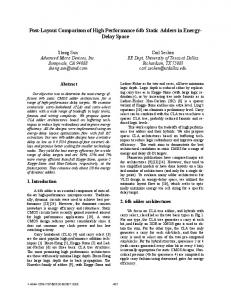
Fig 1: (a) Initial Input Order (b)Sorted input order at the output of input buffer (c)Computed Output order without sorting (d)Output order after sorting(e) Block diagram of MIMO MDC FFT/IFFT processor.
24
International Journal of Computer Applications (0975 – 8887) Volume 89 – No 12, March 2014 same hardware with FFT .For these two systems, there are four FFT/IFFT lengths, that is, N = 2048,1024, 512, and 128 .Here let us take N=2048.In MDC , most of the area is obtained by storage elements , that is, the input buffering stage for radix-4 based FFT needs N/4+ N/2+3N/4 words of memory, and each computing stage needs 3N/4s words of memory, where s represents the stage index. According to this, 2048-pointMDC FFT/IFFT processor, 5112 words of memory are needed. If MDC is used in MIMO-OFDM systems, memory size grows linearly as the number of data stream increases. Even though MDC architecture provides simple control for data flow, most of the previous works use SDF instead of MDC for complexity concern. But if the data streams are properly scheduled, the utilization rate can be made full. This makes MDC suitable for MIMO-OFDM systems.
2.2 Memory scheduling operations
and
butterfly
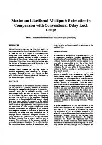
First, the input streams in Figure 1(a) is converted to output stream in Figure 1(b) which is in sorted format. Input stage consists of 12 memory banks which converts the input streams which are parallel into serial blocks, and one butterfly at each stage compute the four data streams. The 12 memory banks are grouped into four memory sets as shown in Figure 2(a), that is, memory sets a, b, c, and d, and it stores the input streams A, B,C, and D, respectively. Two types of grouping methods are available, namely grouping for even indexed symbols and grouping for odd indexed symbols as shown in Fig.2 (a) and Fig.2 (e) respectively. At first 12 memory banks are grouped to four sets {a1, a2, a3}, {b1, b2, b3}, {c1, c2, c3}, and {d1, d2, d3} as shown in Figure 2(a). Each set is one input stream. From the first cycle to 3N/4th cycle, the memory banks keep the first to 3N/4th samples of each input stream. Consider case of N = 2048, the memory banks {a1, a2, a3}, {b1, b2, b3}, {c1, c2, c3}, and {d1, d2, d3} store the samples {1st -512th, 513th –1024th,1025th –1536th ,10537th -2048th } of the first, the second, the third, and the fourth input streams, respectively. From the (3N/4+1)th to the Nth cycle as in Fig.2(b), form scheduling for odd indexed symbols.
Fig 2: Input scheduling. (a) Logical groups of initial memory banks. (b) (3N/4 + 1) th to the Nth cycle. (c) (N + 1)th to the (N + N/4)th cycle. (d) (N + N/4 + 1) th to the (N + N/2) th cycle. Usually N is a power of 2 and implementation of 1/N only involves right shift operation. Therefore, the IFFT share the
At the end of the 2048th clock cycle, the radix-4 butterfly has computed the 2048 samples of stream A, and the memory set {a1, a2, a3} is updated with the 1537th to the 2048th samples of stream B,C, and D, respectively. Similarly, in the next N/4 cycles, the contents in memory set b are updated as shown in Fig. 2(c). The processor reads out the 2048 samples of stream B from the memory banks a1 and {b1, b2, b3} and forwards it to the radix-4 butterfly. Then, the empty memories a1 and {b1, b2, b3} are updated by the first to the N/4th samples of streams and it read-out data from A, B, C and D, respectively, of the second OFDM symbols. Continuing with the example of N = 2048, at the end of the 2560th clock cycle, the radix-4 butterfly has computed the 2048 samples of stream B, and the memories a1 and {b1, b2, b3} are updated with the first to them and then this memory set are updated with the incoming samples from stream B,C, and D. That is, together with the previously stored first to 3N/4th samples, now the radix-4 butterfly can process the samples of stream A, because the (3N/4 + 1)th to the Nth samples are ready at this instant. As only one butterfly is used at each stage, the (3N/4 + 1)th to the Nth samples for the input streams B, C, and D are given to the memories viz. a1, a2, and a3, respectively. At the end of the 2048th clock cycle, the radix-4 butterfly computes the 2048 samples of stream A, and the memory set {a1, a2, a3} is updated with the samples of stream B,C, and D, respectively(samples from 1537th to the 2048th). Likewise, for
25
International Journal of Computer Applications (0975 – 8887) Volume 89 – No 12, March 2014 the next N/4 cycles, the data in memory set b are updated. The procedure is repeated for C and D. The proposed FFT/IFFT processor uses radix-4 butterflies as basic elements for computation. Each stage uses same radix-4 butterfly, where as in the last stage we prefer radix-8 butterfly which can also be configured as a radix-4 butterfly. For the storage of the twiddle factors, we use Complex constant multiplier, replacing ROM.
3. PROPOSEDCOMPLEX MULTIPLIER The hardware construction of FFT/IFFT processors consists of a ROM to store the needed twiddle factors, and then word length complex multipliers to perform FFT computing. However, this results in more complex hardware as well as more cost, thus a bit-parallel complex constant multiplier [8] is used to reduce the cost and hardware complexity. Five operation types are used to perform complex multiplication in the proposed complex multiplier and they are represented from equation (5) to (9). k
W .(a jb) WN k N
N 4
(b ja),
N N k 4 2 (5)
𝑊𝑁𝑘 .
𝑎 + 𝑗𝑏 =
𝑁 𝑘− −𝑊𝑁 2
3𝑁 𝑎 + 𝑗𝑏 , 𝑁/2 < 𝑘 < 4 (6)
3𝑁 4
𝑘−
𝑊𝑁𝑘 . 𝑎 + 𝑗𝑏 = −𝑊𝑁
𝑏 − 𝑗𝑎 , 3𝑁/4 < 𝑘 < 𝑁 (7)
𝑁
𝑊𝑁𝑘 . 𝑎 + 𝑗𝑏 = [𝑊𝑁4
−𝐾
𝑏 + 𝑗𝑎 ]∗ , 1 < 𝑘 < 𝑁/4 (8)
WNk .(a jb) [WNN /2k (b ja)]*,
N N k 4 2
Fig 3: Complex Multiplier. This new multiplication structure is the key component in reducing the chip area and power consumption of proposed FFT/IFFT processor. Fig 3 shows the structure of this complex multiplier also adopts a cascaded scheme to achieve low-cost hardware. Here, two input signals (Iin and Iout) and two output signals (Qin and Qout) this circuit is responsible for the computation of multiplication by a twiddle factor.
4.
RESULTS AND COMPARISON
Code development, synthesis, analysis related to timing and power for the proposed MDC FFT PROCESSOR with variable length for OFDM are carried out in Altera and simulation is done in ModelSim.
4.1. Synthesis output: 4.1.1.
RTL Output and Compilation Report
The RTL output for stage 1 of the processor and the overall RTL out for the MDC FFT Processor is shown in Fig.4 and Fig.5 respectively. The synthesis output shows that the proposed ROM Less MDC FFT processor achieves 2.2% of total logical elements and 2.2% of total combinational fuctions, which was 10.46% for MDC FFT processor with ROM[3].The compilation report for the proposed processor is shown in Fig.7.
(9) This operation results in the twiddle-factor ROM to shrunk significantly. Based on five operation types for complex constant multiplication we propose reconfigurable complex constant multiplier to eliminate the twiddle-factor ROM.
Fig 4: RTL Output of Stage 1.
26
International Journal of Computer Applications (0975 – 8887) Volume 89 – No 12, March 2014
4.1.3 Power analysis The power analysis report for proposed system is shown in Fig.9.The processor consumes a total thermal power of 113.89mW which includes core static thermal power dissipation of 79.94mW, core dynamic static thermal power dissipation and I/O thermal power static dissipation of 33.95mW.
Fig 6: Overall RTL Output for Proposed Processor
Fig 9: Power Analysis Report.
4.2 Simulation output:
Fig 7: Compilation Report of MDC FFT Processor.
The proposed MDC FFT Processor simulation was carried out in Altera ModelSim and the waveforms are shown in the Fig 10. The inputs are given to the processor through the input pins sin1, sin2, sin3, sin4. Similarly, clock pulse is given through „clk‟ pin. The Outputs for the processor are taken from sout1, sout2, sout3, sout4.
4.1.2 Timing analysis The proposed system with complex multiplier achieves a maximum clock set up time of 3.981 ns(251.19MHz) and worst case Tco of 49.314 ns which was 3.986ns (250.82MHz) and 64.228ns respectively for the processor with ROM. The timing analysis report for proposed MDC FFT processor is shown in Fig.8.
Fig 10: Simulation Output.
Fig 8: Timing Analysis Report.
27
International Journal of Computer Applications (0975 – 8887) Volume 89 – No 12, March 2014
5. CONCLUSION In this paper, a ROM less radix-r based MDC MIMO FFT/IFFT processor for processing Ns streams of parallel inputs is proposed. The proposed technique is preferable for MIMO-OFDM baseband processor such as WiMAX [8] or LTE applications. The efficient memory scheduling and constant complex multiplier considerably decreases the chip area because the memory requirement usually dominates the chip area in an FFT/IFFT processor. Therefore, we conclude that the proposed design optimizes area and energy efficient.
6. REFERENCES [1] B. M. Baas (1999), „A low-power, high-performance, 1024-point FFT processor,‟ IEEE J. Solid-State Circuits, Vol. 34, no. 3, pp 380–387. [2] Chu Yu, Mao-Hsu Yen, Pao-Ann Hsiung, and Sao-Jie Chen,(2011),‟ A Low-Power 64-point Pipeline FFT/IFFT Processor for OFDM Applications „IEEE transaction,Vol 57 no.1 [3] Kai-Jiun Yang, Shang-Ho Tsai, and Gene C. H. Chuang, (2013), „MDC FFT/IFFT processor with variable length for MIMO-OFDM systems‟ IEEE transaction, Vol.no. 21, pp- 4. [4] M. S. Patil, T. D. Chhatbar, and A. D. Darji, (2010), “An area efficient and low power implementation of 2048
IJCATM : www.ijcaonline.org
point FFT/IFFT processor for mobile WiMAX,” in Proc. Int. Conf. Signal Process. Commun, pp. 1–4. [5] S. He and M. Torkelson (1996), “A new approach to pipeline FFT processor,” IEEE Int. Parallel Process. Symp. pp. 766–770. [6] T.Sansaloni, A.Perex-Pascual, V. Torres,(2005), “Efficient pipeline FFT processors for WLAN MIMOOFDM systems,” Electron. Lett. Vol. 41, no. 19, pp. 1043–1044. [7] W. Fan and C.S. Choy (2012), “Robust, low-complexity, and energy efficient downlink Baseband receiver design for MB-OFDM UWB system,” IEEE Trans. Circuits Syst. I, Reg. papers, Vol. 59, no. 2, pp. 399–408. [8] Y. Chen, Y.W. Lin and C.Y. Lee (2006), “A block scaling FFT/IFFT processor for WiMAX applications,” in Proc. IEEE Asian Solid-State Circuits Conf., pp. 203– 206. [9] Y.W. Lin, H.Y. Liu and C.Y. Lee (2004), “A Dynamic Scaling FFT Processor for DVB-T Applications,” IEEE journal of solid-state circuits, Vol. 39, no. 11. [10] Y.W. Lin and C.Y. Lee (2007), “Design of an FFT/IFFT processor for MIMO -OFDM Systems,” IEEE Trans. Circuits Syst. I, Reg. Papers, Vol. 54, no. 4, pp 807–815.
28