To perform this cyber-attack, we built a âDelay Boxâ capable of advancing or delaying a slave clock by introducing a malicious offset of a few microseconds.
Cyber-attack on Packet-Based Time Synchronization Protocols: the Undetectable Delay Box Sergio Barreto, Member, IEEE, Aswin Suresh, Member, IEEE Jean-Yves Le Boudec, Fellow, IEEE Laboratory of Communications and Applications 2 ´ Ecole Polytechnique F´ed´erale de Lausanne (EPFL), CH-1015, Lausanne, Switzerland Abstract—We present a cyber-attack on packet-based time synchronization protocols (PBTSP) with high-accuracy requirements. The cyber-attack is undetectable from the PBTSP’s perspective and exploits a vulnerability that is in the nature of all PBTSPs. It can be successfully performed regardless of the cryptographic protocol that the PBTSP is protected with and it is undetectable by the clock-servo algorithm inside the target slave clock. To perform this cyber-attack, we built a “Delay Box” capable of advancing or delaying a slave clock by introducing a malicious offset of a few microseconds. We run experimental tests to the delay box to prove the magnitude of the attack and to confirm undetectability. We discuss possible countermeasures for this type of attack.
I.
I NTRODUCTION
We are interested in sensor networks with high-accuracy in a given time reference. For example, phasor measurement units (PMUs) in transmission networks require a synchronization accuracy of 1µs according to the standard; in distribution networks, where such deployments are believed to occur in the near future [1], PMUs require 100ns accuracy or less for real-time state estimation [2], [3]. Another application for high accuracy can be found in [4] where sub-ns synchronization accuracy between clocks is required among 10,000 sensors to trace galactic cosmic rays. The state-of-the-art synchronization technology for achieving high-accuracy in time measurement is GPS. However, in recent years, packet-based time synchronization protocols (PBTSPs) with high accuracy (e.g., Precision Time Protocol (PTP) [5]), have come to be of particular interest in sensor networks because they provide enhanced security and can work in cases where physical locations make GPS signal inaccessible. Notwithstanding, in PBTSPs there remains a vulnerability that cannot be corrected by cryptography and is in the nature of all of them. The vulnerability is based on the theory explained in detail in [6], where the authors prove that in any PBTSP it is impossible to measure asymmetries in the propagation delay by the protocol itself, for instance, any difference in the forward and backwards path must come from outside the protocol. Therefore, every PBTSP makes an assumption on the propagation delays between master and slave clocks: either they are symmetric or the ratio in the propagation delays is known. This assumption can be exploited by a delay attack. In this paper we mount a delay attack against White Rabbit (WR) [7]. WR is a technology that achieves high synchronization accuracy (sub-ns). It combines several standard protocols such as Synchronous Ethernet (Sync-E) [8], PTP and a precise
measurement of the reception timestamps (see appendix B in [7] for details). Sync-E is used to distribute the frequency of the master clock to the slaves; PTP is left for offset compensation, which makes WR a target for delay attacks. Depending on its magnitude and the application, the delay attack could have disastrous consequences. Following the PMU example, injecting a delay, which causes an offset of a few µs, would mean errors in the order of a few mrad in the synchrophasor estimation. In active distribution-networks (ADNs), the phase-angle differences between buses are a few mrad as well, therefore the delay attack could cause a domino effect by altering the state-estimation, which alters grid-protection applications that use it, which leads to fault-location errors and blackouts [9]. In this paper we present the Delay Box, a device capable of producing a delay that deceives the WR protocol and injects an undetectable malicious offset of a few microseconds or more either in the forward or in the backwards direction relative to the master clock. The Delay Box operates at the physical layer and is therefore undetected by any encryption or authentication mechanism at layer 2 or above. Mounting an attack with the Delay Box against, for example, a smart grid, would not be a difficult task. Many overhead lines contain an optical line with physical-layer repeaters placed every few kilometers on the poles. Climbing up a pole is all that one needs to do in order to insert a Delay Box in the optical line. In Section II we present a state-of-the-art analysis in delay attacks to PBTSPs. In Section III we describe our attack and provide an analysis of the WR offset-computation in the presence of a delay attack. In Section IV we explain how the attack can be unnoticed by the clock-servo. In Section V we describe how to build the Delay Box. In Section VI we describe the experiments and tests done on the Delay Box. In Section VII we analyze possible countermeasures, and we conclude the paper in Section VIII. II.
S TATE OF THE A RT
Security in PTP has been extensively studied in literature [10], [11], [12]. However, delay attacks on PTP have not been addressed in the same depth. In [13] there is a full description of security requirements in PBTSPs, where delay attacks are mentioned as high impact and “mechanisms” should be included in the PBTSP implementation to protect against them. In [14], the authors analyze delay attacks from a gametheoretic perspective; they propose several attack vectors,
stating that a “successful strategy” manipulates the delay asymmetry; as countermeasures they propose protecting the protocol with multiple paths between master and slave clocks, or with a drop-threshold taken from RTT measurements that can be computed precisely. However, the study in [14] is purely theoretical so no implementation is given, and they do not provide a closed-form expression to calculate the injected offset in the slave clock during the delay attack. In [15], the authors study the implications of inserting an asymmetric delay in NTP and PTP. However, their conclusions about the effects of injecting a one-way delay in any direction are not accurate, as we show in Section III-C. In [16], the authors also analyze delay attacks: In their attack work-flow they describe that the attacker should intercept and delay the arrival time of both Sync and Delay Req packets. But we show as in [14] that the best attack consists in delaying only Sync or Delay Req packets, not both. The authors of [16] also propose a countermeasure based on a threshold given by the ratio between the clock rates of master and slave. We did not find any other work that addresses the analysis for undetectability or mentions how an undetectable delay attack is implemented. To the best of our knowledge, there is no previous work on security for the WR protocol. WR uses a specific asymmetry definition that makes our delay-attack analysis different from [14], [15] or [16]. In addition, WR’s specification mandates the use of bidirectional optic-fiber uplinks which requires special handling, as explained in Section V. Nonetheless, for other security-related analysis, any work done on PTP can be transported to WR’s PTP engine. III.
D ESCRIPTION OF THE DELAY ATTACK
In this section we describe our attack, we provide an overview of a standard WR’s offset-correction process and an analysis of the malicious offset induced by a delay attack either in the master-to-slave or the slave-to-master direction. The notation used in this section is summarized in Table I. A. Undetectable Delay Attack Our goal is not only to inject a malicious offset to the slave clock. We start our attack by adding a one-way delay in the communication path between the master and slave clocks. We know that the effect of this is an asymmetry unknown to the protocol, which cannot be compensated by itself. Depending on which direction we insert the one-way delay in the communication path, we can make the slave clock go ahead or behind the master clock. Concretely, we proceed as follows. We insert into the optical fiber used by WR, which typically is bidirectional, a self-powered repeater box built by us. We bridge the gap in the bidirectional fiber by two unidirectional fibers and appropriate optical/electrical converters. In one direction we use a short fiber (2m), and in the reverse direction we use a fiber coil of one or several kilometers whose length is proportional to the delay we want to introduce in the communication path. To avoid being cut by cryptography, we use equipment that operates in the physical layer, below any MAC-based or IPbased security protocols.
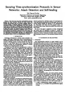
Fig. 1.
White Rabbit link delay model taken from [7]
Finally, we need to address the fact that the internal oscillator of the WR slave clock is governed by a clock-servo with a particular stiffness that limits the rate at which the oscillator can change its time. The injected offset in a delay attack could cause a step change in time which can produce an error or alarm in the clock-servo. To address this problem, we introduce the delay in the form of a ramp, with increments that are small enough to be unnoticed by the clock-servo. The computation of the largest possible increment is given in Section IV. B. Offset Estimation in WR In this section, we present a brief theory on the WR’s offset-estimation, that is used in the derivation of the malicious offset induced by a delay attack, as described in Section III-C. Table I gives the notation used in the rest of the section. Typical PTP timestamps (t1 , t4p for master’s timestamps and t2p , t3 for slave’s timestamps) are used to compute the round trip delay delayM M as delayM M = (t2p
t1 ) + (t4p
(1)
t3 )
where subscript p refers to the precise measurement of the timestamp (see Section B.5 of [7]). delayM M can be computed correctly regardless of the offset between the master and slave clocks. The link-delay model used in WR is depicted in Figure 1. The WR specification [7] assumes fixed delays are due to transmission/reception circuitry and variable delays are due to transmission media. Under these assumptions, we can express the delay between master and slave as the sum of the circuitry and transmission media delays delayM S =
T XM
+
RXS
+
(2)
MS
WR defines a relative delay coefficient ↵ (i.e. relationship between propagation delays) given by MS
↵=
SM
(3)
SM
delayM M can also be written as the sum of the delays in the transceivers and fibers delayM M = where = T XM + 4 we can write MS
RXS
=
+ +
MS
+
T XS
+
1+↵ (delayM M 2+↵
(4)
SM RXM .
From 3 and
)
(5)
From 2 and 5 delayM S =
T XM
+
RXS
+
1+↵ (delayM M 2+↵
) (6)
TABLE I.
N OTATION USED THROUGH S ECTION III.
Notation Off
Equation 15 shows that an attack vector with DM S = DSM 6= 0 produces no damage for very small values of ↵ (which is the typical case in WR networks). It also proves that the slave’s clock can be either ahead or behind the master’s clock, depending on the value of DM S and DSM . IV. M AXIMUM DELAY INCREMENT
Meaning Offset between master and slave clocks. Negative when slave is ahead of master. Total delay from X to Y . X, Y 2 {M, S}; X = Y denotes round trip delay. Transceiver and circuitry delays. A 2 {T X, RX}, X 2 {M, S}. Without subscript, denotes sum of all fixed delays. Delay in fiber from X to Y . X, Y 2 {M, S}; X = Y denotes round trip delay. Relative delay coefficient defined in Equation 3 Total additional delay introduced from X to Y in the delay attack, relative to the unattacked case. Stands for the real value of Exp subject to no attack. Stands for the real value of Exp subject to the delay attack. Value of Exp as considered by WR software.
delayXY AX
XY
↵ DXY
Exp Expatt Exp0
As discussed in Section III-A the delay inserted by the Delay Box needs to be applied in small increments, to be unnoticed by the clock servo. In this section, we provide a formulation for such a maximum delay increment, say D⇤ . Regardless of the PBTSP, we can measure the frequency drift of a slave clock referenced to the master clock with two different sets of pings (exchange between Sync and Delay Req messages). Using the same timestamping convention as Section III-B (t1 , t2p ) and assuming two consecutive ping exchanges k and n with n > k, we can express the frequency drift aslv in the WR protocol by
Finally, the slave’s clock offset is calculated in WR from one ping timestamps and master-to-slave delay as Off = t1
t2p + delayM S
(7)
C. Derivation of the malicious offset induced by a delay attack In this section we derive an expression for the clock offset induced during a delay attack as a function of the delay DSM [resp. DM S ] introduced by the Delay Box from slave to master [resp. from master to slave]. Equation 7 relates Off and delayM S at any given time Offatt = t1
t2p + delayM Satt
Off0 = t1
(8)
t2p + delay0M S
(9) 0
Combining equations 8 and 9, and assuming Off = 0 when WR protocol converges we have delay0M S
Offatt = delayM Satt
(10)
aslv =
delay0M S
T XM
=
+ T XM
RXS
+
+
MS
RXS
+
+ DM S 0 MS
1 + ⌘att = 1 + ⌘slv +
Offatt =
DM S
DSM 2
+
↵(DM S + DSM ) 4
(15)
Di TSync
(17)
Di = ⌘att TSync D⇤ ⌘slv + ⌘clk ⌘slv TSync D⇤ TSync (⌘clk ⌘slv +
(12)
Using 3, 10, 11 and 13, we have 1+↵ Offatt = DM S (DM S DSM ) (14) 2+↵ According to [7], the value of ↵ is typically small, thus we can approximate 14 to
(16)
where Di is the delay introduced by delay component i and TSync is the sending period for the Sync messages corresponding to tn1 tk1 . Let’s define the maximum frequency drift update (in PPM) of the clock-servo in a slave as ⌘clk , then we know that the attack is undetected by the clock-servo as long as ⌘att ⌘clk ⌘slv . Thus, by using Eq. 17 and applying the constraints described we can find an expression for the maximum delay increment that is unnoticed by the clock-servo
(11)
By using 6 and considering that RT T can be measured precisely by using PTP timestamps 1+↵ delay0M S = T XM + RXS + (delayM Matt ) 2+↵ 1+↵ delay0M S = T XM + RXS + ( M S + SM 2+↵ + DM S + DSM ) (13)
tk2p tk1
Note that aslv is bounded by the resultant frequency stability given by Sync-E, such that 1 ⌘slv aslv 1 + ⌘slv , where ⌘slv is the syntonization accuracy of the Sync-E’s syntonized slave-clock expressed in PPM, which is upper-bounded by the ITU-T G.8262 standard in 4.6PPM [8]. In the presence of an attack, it follows that the frequency drift (1 + ⌘att ) produced by the attack has the form
We can rewrite equation 2 in our terms as delayM Satt =
tn2p tn1
2⌘slv )
The value of ⌘clk depends on the clock-servo’s implementation and it can be metrologically characterized in the laboratory. In our experiments we used ⌘clk = 5PPM [17], ⌘slv = 10PPB thus D⇤ ⇡ 4.98µs. V.
T HE MAKING OF THE UNDETECTABLE DELAY BOX
In this section we explain how we built the Delay Box, illustrated in Figure 2. The Delay Box is composed of N interconnected delay components, where each delay component can be activated or deactivated using a control signal. All delay components provide a fixed delay Di satisfying the property Di := 2i 1 D⇤ , i = 1, 2, . . . , N , where D⇤ is the maximum delay increment, as discussed in Section IV. The purpose of this design is to implement a ramp, so that we can gradually inject 2N 1 different delays to reach a target delay D without
Fig. 2.
Delay Box diagram
Fig. 4.
Testbed used for the experiments at the laboratory.
requires only low-end, non-expensive equipment that is readily available in any consumer optic-fiber shop. Fig. 3.
Diagram of a single delay component
being noticed by network operator. The set of delays that the Delay Box is able to produce is in the range [0, 2N 1 D⇤ ] by increments of D⇤ , and the largest injected delay Dmax is given by N X Dmax = D i = 2N 1 D ⇤ (18) i=1
The diagram for a single delay-component is depicted in Figure 3. Each delay component consists of two optical-toelectrical-to-optical transponders (OEOs). Each OEO is a 3Ports small form-factor pluggable (SFP) to SFP, 1.25G OEO transponder manufactured by Fiberstore, with full 3R support (reamplification, reshaping, retiming). The SFP interface help us to support for either bidirectional or unidirectional fibers to overcome the restriction imposed by WR, by mandating the use of bidirectional fiber links.
The interfaces labeled with A and B from each OEO are connected back-to-back, such that in each A interface there is a very short fiber link (2m in our testbed). However, in the B interface, we connect a very long fiber in one direction (e.g., T Xlef t to RXright ), that is entangled in a coil to achieve the desired delay Di . In the other direction (e.g, T Xright to RXlef t ) we use another very short fiber. Switching from A interface to B interface and vice versa is manually triggered by a digital input available on each OEO, such that both OEOs switchover at the same time, without perturbing any hardware link-down detection mechanism. In our testbed we used a push button to manually trigger the switchover of both OEOs. We connect the push button to the trigger input of each OEO, using copper cables of same length to ensure that both OEOs receive the signal at the same time. By combining the trigger mechanism, the fact that the circuitry that makes the switch over in the OEO is orders of magnitude faster than the hardware link-down detection mechanism (⇡ 50µs vs < 10ms), and the fully support of Sync-E, we can prevent traffic disruption during the insertion or removal of other delay components. Summarizing, it is possible to have 2N 1 different delays with a fixed D⇤ increment step. Note that our Delay Box
VI.
E XPERIMENTS WITH THE D ELAY B OX
In this section, we present the experimental tests made on the Delay Box. We define three cases based on the attacker’s point of view: reference, when there is no Delay Box (i.e., no attack in the system); silent, when we have inserted a Delay Box but with all delay components deactivated (i.e., when delay is set to D = 0); and active, when the Delay Box is performing a delay attack to the system (i.e., when D > 0). We performed 100 independent measurements for measuring the offset on each case (reference, silent, attacks), and we took 500 independent measurements for the measurements in Section VI-C. A. Hardware An illustration of the testbed is shown in Figure 4. Master and slave clocks are Simple PCIe FPGA mezzanine card (FMC) Carriers (SPECs) inside a regular PC, that provides power and console access. Each SPEC has a 5 channel FMC digital I/O module and the specifications on this card can be found in [18]. The dark boxes labeled with OEO are the OEOs described in Section V. All OEOs and SFPs transceivers come from the same manufacturer to help in symmetric design. Transceivers facing the SPEC cards (WR’s master and slave clocks) are bidirectional transceivers following the standard described in [7]; all other transceivers are unidirectional 1000Base-LX SFPs. The coil is approximately 1km ±15m long to meet the 4.98µs delay requirement. Any other fiber used is 2m ±20cm long. All tests performed and reported in this paper where done under the same temperature conditions of 23°C ±1. To prove synchronization and the effect of the attack, in one of the FMC DIO’s channel we produce a PPS signal, and we use a Rohde-Schwarz RTO 1044 oscilloscope with 10GS/s sampling rate to measure the offset difference between the master’s PPS and the slave’s PPS signal. We set the trigger on the positive edge of the master’s PPS signal at 1.48V. B. Attack results In this section, we show the results from attacking with one single delay component (i.e., from Eq. 18 we set N = 1, D = D⇤ = 4.98µs). In figure 5 we show slave’s PPS in the
Fig. 7. Impact of a delay attack using a Delay Box in the master-to-slave direction with D = D ⇤ = 4.98µs Fig. 5.
Performance of the Delay Box with D = 0, in silent mode
directly the mean of the offset injected by the Delay Box and its variance. For the theoretical estimation, recall from Section III-C that DM S and DSM are the additional delays that are introduced in the master-to-slave or the slave-to-master directions in the presence of an attack. All OEO converters and SFP transceivers come from the same manufacturer and we assume all devices of the same kind produce the same delay. Under this assumption, we can express the delay DM S and DSM as DM S =DCTDBM S + DSM =DCTDBSM +
Fig. 6. Impact of a delay attack using a Delay Box in the slave-to-master direction with D = D ⇤ = 4.98µs
reference case (blue dotted line) and the silent case (red lined) against the master’s PPS (black solid). Note that the difference between the PPS signals in the reference and the silent case deviate by roughly 100ps. As typical WR synchronization accuracy is a few hundreds of picoseconds [19], Figure 5 confirms that synchronization accuracy is not compromised in the presence of the Delay Box in silent mode (with D = 0), and thus confirms that the Delay Box in silent mode is truly undetectable. Figure 6 shows the impact of the attack when the Delay Box is placed in the slave-to-master direction with D = D⇤ ⇡ 4.98µs; Figure 7 shows the same attack with the Delay Box inserted in the opposite direction. We can see that in both cases a malicious offset of 2.47µs and +2.47µs injected in the slave clock depending on the placement of the Delay Box. With these results we show that an attacker can use the Delay Box to forward or delay a sensor’s clock at will. C. Validation of experimental results To validate the experimental results from Section VI-B on the malicious offset injected by the Delay Box, we compare them to the theoretical values obtained using the equations described in Section III-C. For the experimental results, the oscilloscope can give
1km
(19)
2m
where DCTDBM S and DCTDBSM are the delays in the OEO converters and SFP transceivers in the Delay Box in the masterto-slave and the slave-to-master directions respectively; 1km is the one-way delay of the 1km fiber coil and 2m is the one-way delay of the 2m fiber. To compute DM S and DSM we measure separately the one-way delays 1km , 2m , DCTDBM S and DCTDBSM . For measuring one-way delays, we follow the procedure suggested by Section 4.2 of [20] and we take 100 samples for each measurement. After computing the theoretical offset using Eqs. 19 and 14, we need to take into account the systematic errors incurred during the experiments. We define the systematic errors as the slave’s clock offset obtained by the experiments minus the slave’s clock offset obtained by the theoretical estimation when the Delay Box is set to a delay D = 0. The results showed systematic errors of the order of 300ps with a 95% confidence interval of the order of 15ps. Lastly, we subtract the systematic errors from the experimental results to compare them to the theoretical estimation. When the Delay Box is inserted in the slave-to-master direction, the theoretical estimation predicts that the injected offset injected is 2.4681µs with an uncertainty of ±15ps at 95% confidence level. The measured offset is 2.4682µs with an uncertainty of ca. ±200ps, which indicates a satisfactory match. In the master-to-slave direction, the predicted offset is 2.4680µs ± 15ps and the measured one is 2.4680µs ± 200ps, also indicating a satisfactory match.
VII.
D ISCUSSION
We propose the following countermeasures to delay attacks: 1) Monitor the delayM M as reported by the software as it increases by a large amount when the 1-km fiber is present. However, in a real scenario this could be difficult because network operators typically do not monitor the RTT between all devices in a LAN, but just between selected “core” network elements. Nonetheless, imagine an attack where the network undergoes maintenance work and a symmetric delay (DM S = DSM 6= 0) is initially inserted by an insider. This action would increase the delayM M , but is unlikely to be noticed as there would be no effect on the time synchronization, and the increase could be attributed to possible hardware changes during the maintenance window. Later, an asymmetric delay can be introduced without changing delayM M by transferring the delay DM S to DSM or vice versa, which would make the attack undetectable to RTT measurements. Still, continuous monitoring and reporting of any suspicious changes in RTT is probably one of the few effective countermeasures. 2) Use redundant and disjoint communication paths between master and slave clocks; or use redundant primary reference-sources (GPS). Then, by using a voting or discarding algorithm we could identify the delayed message and take actions. Note that the discard algorithm would add complexity to the clock-servo. The effectiveness of this method assumes that the majority of the communication paths (or majority of the primary reference-sources) are not compromised by the attacker. 3) Use packet duplication. A robust implementation of a redundancy protocol such as PRP [21] or iPRP [22] could be used as a countermeasure. This will work assuming the attacker cannot attack all the alternate paths at the same time. 4) Prefer encryption over authentication in PBTSPs. Encryption prevents the attacker from retrieving information such as Sync or Delay Req message frequency, which can be used to calculate the maximum delay increment D⇤ as shown in Section IV. However, the maximum message frequency could be inferred, which could be use to derive a conservative value of D⇤ . VIII.
C ONCLUSIONS
We have proposed and built a Delay Box out of components that can be easily acquired in any fiber shop. We have implemented a delay attack over a WR network, and we have injected an offset of 2.47µs or +2.47µs that was undetected by the protocol and unnoticed by the clock-servo. It did not show any warning or error message, therefore it was also not possible for a network operator to detect it. The consequences of this delay attack can be of significance, specially in time networks with high-accuracy requirements.
[2] [3]
[4]
[5] [6] [7] [8] [9] [10]
[11]
[12]
[13] [14]
[15]
[16] [17] [18] [19]
[20] [21]
R EFERENCES [1]
Marco Pignati, Miroslav Popovic, Sergio Barreto, Jean-Yves Le Boudec, Mario Paolone, et al. Real-time state estimation of the epfl-campus medium-voltage grid by using pmus. In The Sixth Conference on Innovative Smart Grid Technologies (ISGT2015), 2014.
[22]
P. Castello, M. Lixia, C. Muscas, and P.A. Pegoraro. Impact of the model on the accuracy of synchrophasor measurement. Instrumentation and Measurement, IEEE Transactions on, 61(8):2179–2188, Aug 2012. P. Romano and M. Paolone. Enhanced interpolated-dft for synchrophasor estimation in fpgas: Theory, implementation, and validation of a pmu prototype. Instrumentation and Measurement, IEEE Transactions on, 63(12):2824–2836, Dec 2014. Guanghua Gong, Shaomin Chen, Qiang Du, Jianming Li, Yinong Liu, and Huihai He. Sub-nanosecond timing system design and development for lhaaso project. Proceedings of ICALEPCS2011, Grenoble, France, 2011. IEEE Standard for a Precision Clock Synchronization Protocol for Networked Measurement and Control Systems. http://ieeexplore.ieee. org/stamp/stamp.jsp?tp=&arnumber=4579760. N.M. Freris, S.R. Graham, and P.R. Kumar. Fundamental limits on synchronizing clocks over networks. Automatic Control, IEEE Transactions on, 56(6):1352–1364, June 2011. E Cota, Maciej Lipinski, Tomasz Wlostowski, E Bij, and Javier Serrano. White rabbit specification: Draft for comments. v2. 0, http://www.ohwr.org/documents/21, 2011. 2007 Timing characteristics of a synchronous Ethernet equipment slave clock (EEC), ITU-T Std. G.8262. http://www.itu.int/rec/T-REC-G. 8262. Zhenghao Zhang, Shuping Gong, A.D. Dimitrovski, and Husheng Li. Time synchronization attack in smart grid: Impact and analysis. Smart Grid, IEEE Transactions on, 4(1):87–98, March 2013. J.-C. Tournier and O. Goerlitz. Strategies to secure the ieee 1588 protocol in digital substation automation. In Critical Infrastructures, 2009. CRIS 2009. Fourth International Conference on, pages 1 –8, 27 2009-april 30 2009. A. Treytl and B. Hirschler. Security flaws and workarounds for ieee 1588 (transparent) clocks. In Precision Clock Synchronization for Measurement, Control and Communication, 2009. ISPCS 2009. International Symposium on, pages 1 –6, oct. 2009. A. Treytl, G. Gaderer, B. Hirschler, and R. Cohen. Traps and pitfalls in secure clock synchronization. In Precision Clock Synchronization for Measurement, Control and Communication, 2007. ISPCS 2007. IEEE International Symposium on, pages 18–24, Oct 2007. T. Mizrahi. Security requirements of time protocols in packet switched networks. RFC 7384, October 2014. T. Mizrahi. A game theoretic analysis of delay attacks against time synchronization protocols. In Precision Clock Synchronization for Measurement Control and Communication (ISPCS), 2012 International IEEE Symposium on, pages 1–6, Sept 2012. M. Ullmann and M. Vogeler. Delay attacks implication on ntp and ptp time synchronization. In Precision Clock Synchronization for Measurement, Control and Communication, 2009. ISPCS 2009. International Symposium on, pages 1–6, Oct 2009. Qingyu Yang, Dou An, and Wei Yu. On time desynchronization attack against ieee 1588 protocol in power grid systems. In Energytech, 2013 IEEE, May 2013. David L Mills and Poul-Henning Kamp. The nanokernel. In Proceedings of the Precision Time and Time Interval (PTTI) Applications and Planning Meeting, 2000. Seven Solutions. White rabbit spec and fmc dio specifications. http: //www.sevensols.com/en/products.html. M. Lipinski, T. Wlostowski, J. Serrano, P. Alvarez, J.D. Gonzalez Cobas, A. Rubini, and P. Moreira. Performance results of the first white rabbit installation for cngs time transfer. In Precision Clock Synchronization for Measurement Control and Communication (ISPCS), 2012 International IEEE Symposium on, pages 1–6, Sept 2012. Grzegorz Daniluk. White rabbit calibration procedure. v1. 0, http://www.ohwr.org/documents/213, 2014. IEC 62439-3 Standard. Industrial communication networks: High availability automation networks, 2012. M. Popovic, M. Mohiuddin, D.-C. Tomozei, and J.-Y. Le Boudec. iprp: Parallel redundancy protocol for ip networks. In Factory Communication Systems (WFCS), 2015 IEEE World Conference on, pages 1–4, May 2015.