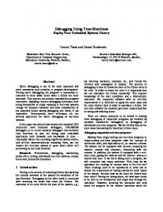
FPGA-Realization of Vector Control for PMSM Drives Nguyen Vu Quynh1,a, Ying-Shieh Kung 2,b, Pham Van Dung3,c, Kuan-Yuen Liao4,d and Sheng-Wei Chen5,e 1,2,3
Department of Electrical Engineering, Southern Taiwan University of Science and Technology, Tainan, Taiwan 1
Department of Electrical Engineering, Lac Hong University, Dong Nai, VietNam
4, 5
Chip Application Section, Energy and Agile System Department, Metal Industries Research & Development Centre, Taipei, Taiwan a
[email protected],
[email protected],
[email protected], d
[email protected],
[email protected]
Keywords: Vector Control, VHDL, FPGA, PMSM, SVPWM. Abstract The design and implementation of a vector control for Permanent Magnetic Synchronous Motor (PMSM) based on Field Programmable Gate Array (FPGA) technology is presented in this paper. Firstly, a Space Vector Pulse Width Modulation (SVPWM) scheme, vector control method and PI controller are derived. Secondly, the Very-High-Speed IC Hardware Description Language (VHDL) is adopted to describe the behavior of the aforementioned control algorithms. Finally, an experimental system is setup to evaluate the effectiveness and correctness of the proposed vector controller for PMSM drives. Introduction PMSM has been used in many automation fields such as robot, metal cutting machines, precision machining etc, because of its advantages of superior power density, high performance motion control with fast speed and better accuracy [1-2]. Therefore, PMSM’s controller plays a very important role. Especially, the vector control technique with the advantages of making the non-linear and coupling characteristics of PMSM decoupled, has been become a popular application technique in PMSM drives. The basic idea of the vector control is to decompose flux current vector into the excitation current and torque current to produce torque, and to the two components perpendicular to each other and achieve mutual decoupling by the coordinate transformation method on the oriental coordinate in a magnetic field [1]. As the results, controlling the PMSM is like to controlling a DC motor. Additional, many conventional controls use Digital Signal Processor (DSP) in most studies. Unfortunately, DSP suffers from long time of development and exhaust resources of CPU. The technology of FPGA with great advantages of programmable hard-wired feature, fast computation ability, shorter design cycle, embedded processor, low power consumption and higher density. On the other hand it can provide an alternative solution for these issues and is more suitable for the implementation of digital system [3-5] than conventional DSPs. Therefore, in this paper, the vector control is firstly applied to the PMSM and FPGA is adopted to realize the overall algorithm of the vector controller. Vector Control Design The typical mathematical model of PMSM is derived in two-axis d-q synchronous rotating reference frame:
L did r 1 s id e q iq vd dt Ld Ld Ld
(1)
diq
(2)
dt
e
Ld r K 1 id s i q e E vq Lq Lq Lq Lq
where vd, vq are the d and q axis voltages; id, iq, are the d and q axis currents, rs is the phase winding resistance; Ld, Lq are the d and q axis inductances; e is the rotating speed of magnet flux; K E is the permanent magnet flux linkage. In the current loop controller design, it is shown in Fig.1 which includes PI controller, Clarke (Fig.2a), modified Clarke-1 (Fig.2b), Park (Fig.3b), Park-1 (Fig.3a) coordinate transformation, SVPWM, current detection pulse signal detection of the encoder, etc. After using vector control (control id* to 0 in Fig.1), it will make the non-linear and coupling characteristics of PMSM become decouple. Thus, the torque magnitude control of PMSM is only need to control the current in the direction of q-axis. As the results, the torque of PMSM is only dependent on iq: 3P Te K E iq K t iq (3) 4 With the consideration of the mechanical load, the overall dynamic equation of PMSM drive system can be computed by: Jm
d r Bm r Te TL dt
(4)
where Te is the motor torque, P is the pole pairs, Kt is the torque constant, Jm is the inertial value, Bm is the damping ratio, TL is the external torque and r is the rotor speed. Space Vector Pulse Width Modulation (SVPWM) SVPWM is a special switching scheme of a 3-phase power converter with the six power transistors. According to the ON/OFF switching of upper transistors in 3-phase power converter, there have eight possible combinations. The SVPWM technique is applied to approximate the reference voltage Uout, and it combines of the switching pattern with the basic space vectors. Therefore, the motor-voltage vector Uout will be located at one of the six sectors (S3, S1, S5, S4, S6, S2) at any given time. Thus, for any PWM period, it can be approximated by the vector sum of two vector components lying on the two adjacent basic vectors, as follows: T T T (O or O111) (5) U out 1 U X 2 U X 60 0 000 T
T
T
Where T0 =T - T1 - T2 and T is half of PWM period. Additional, any output voltage can be projected into each adjacent basic vector in SVPWM strategy. For example, the output voltage vector Uout in the sector S3 can be the combination of U0 and U60 shown in Fig.4c. Therefore, the calculation of T1 and T2 can be shown as follows: 2 U 0 VDC 3 1 1 U 60 VDC VDC 3 3
(6) (7)
If we substitute (6)~(7) into (5), we obtain U out
T V V T1 T T 2 U 0 2 U 60 1 ( VDC ) 2 ( DC DC ) V V T T T 3 T 3 3
(8)
With V
T2 3T
V DC
(9)
V
T 2 T1 2 T1 1 V DC 2 V DC V DC V 3T 3T 3T 3
(10)
From (9) and (10), the T1 and T2 can be obtained as follows T1
T (3V 3V ) 2VDC
(11)
and T2 3
T V VDC
(12)
In the similar way, the T1 and T2 in other sector can be derived and be rearranged in Table 1, which TX, TY and TZ are represented as the followings: T (13) TX 3 V VDC T TY (3V 3V ) 2VDC T TZ (3V 3V ) 2VDC
(14) (15)
If it is at the saturation condition where T1 + T2 > T, the T1 and T2 should be modified as: T T1 T2 T T2 T1 T2
T1SAT T1
(16)
T2 SAT
(17)
After the calculation of T1 and T2, it has to re-transfer it to the duty cycles and CMPx values to generate the PWM output signals for controlling the power transistor switching time shown in Fig.4a. First, the duty cycles are defined as Taon, Tbon, Tcon, and calculated as follows: Taon = (T-T1 -T2)/2 = T0/2 (18) Tbon = Taon +T1 (19) Tcon = Tbon+T2 (20) Then, the CMPR1~3 values can be obtained in Table 2 depend on the sector number. From Fig. 4b, the sector according to the following rules: If Vrfx > 0 then a=1 else a=0; (21) If Vrfy > 0 then b=1 else b=0; (22) If Vrfz > 0 then c=1 else c=0. (23) Then Sector = a+2b+4c. (24) In addition, from equations (12)~(14) and Fig. 2(b), we have. Vrfx Tx T 3T V (25) y V rfz DC Vrfy TZ Therefore, Tx, Ty and Tz can be derived directly from Vrfx, Vrfy and Vrfz. Finally, the computation procedures of SVPWM design can summary as follows: Step 1: Determination of the sector according to the rule shown in (24), where Vrfx , Vrfy , Vrfz are the input signals of the SVPWM block circuit in Fig.1. Step 2: Calculation of TX, TY and TZ from (13) ~(15). Step 3: Determination of T1 and T2 from Table 1. If it is at the saturation condition, we can use (16)-(17) to modify the T1 and T2. Step 4: Determination of the duty cycle Taon, Tbon Tcon from (18)~(20). Step 5: Assignment of the duty cycles to CMPR1, CMPR2 and CMPR3 from Table 2.
Design of Vector Controller of PMSM Based on FPGA Figure 5 illustrates the block diagram and FPGA-based current vector controller. The FPGA chip adopts herein is an Altera DE2 Cyclone II EP2C35F672, which has 33,216 LEs, 105 M4K RAM blocks 483,840 total RAM bits, 35 embedded multipliers, 4 PLLs, 475 user I/O pins, fine Line BGA 672-pin package, and a Nios II embedded processor which has a 32-bit configurable CPU core, 16 M byte Flash memory, 1 M byte SRAM and 16 M byte SDRAM, is used. The internal circuit in Fig. 5(b) comprises the circuits of CCCT (Current controllers and coordinate transformation), AD interface, QEP interface and SVPWM. Detailed SVPWM designed circuit is shown in Fig.6 which includes a SVPWM algorithm implemented by FSM (Finite State Machine) method, a triangular wave generation, a comparator and a dead-band generation. The sampling frequency of current control loop is designed with 16kHz. The operating clock rate of the designed FPGA controller is 50MHz and the frequency divider generates 50 Mhz (Clk) and 16 kHz (Clk-cur) clock to supply all module circuits in Fig. 5(b). Under the proposed design method, the resource usage of the proposed current vector controller is that the SVPWM circuit needs 1,221 LEs (Logic elements), the CCCT circuit needs 864 LEs, QEP interface circuit needs 114 LEs and ADC interface circuit needs 136 LEs. Experimental System and Results The overall experimental system depicted in Fig.1 includes an FPGA (Cyclone II EP2C35F672), a voltage source IGBT inverter and a PMSM. The specifications of the PMSM are rs = 0.63 , L =2.77mH and 4 pole pairs. The input voltage, continuous current, rating torque, rating speed and continuous power of the PMSM are 220V, 12A, 2.3 N-m, 3000rpm and 750W, respectively. A rotary encoder with a resolution of 2500pps is attached on the PMSM as the rotor position sensor. The inverter has three sets of IGBT power transistors. The collector-emitter voltage of the IGBT is rated 600V; the gate-emitter voltage is rated 20V, and the DC collector current is rated 25A and in short time (1ms) is 50A. The photo-IC, Toshiba TLP250, is used in the gate driving circuit of IGBT. Input signals of the inverter are PWM signals from the FPGA device. For validating the effectiveness of the current vector control in Fig. 1, the input current command, (id* , iq* ) (0 A, 1A) is set, and the measured currents of id , iq is shown in Fig. 7(a), the corresponding currents in a-b-c axes and in axes are shown in Fig. 7(b) and Fig. 7(c), respectively. In Fig. 7, due to the EMI effect in the motor driver board, the measured current has a little ripple. Nevertheless, the experiment result is still presented that the measured current could tracks the current command well. Furthermore, it not merely validates the function of the vector control, but also could make the PMSM decouple. Therefore, the experiment shown in Fig. 7 demonstrates the effectiveness and correctness of the proposed FPGA-based vector controller for PMSM. Conclusion This study has been successfully presented a vector control for PMSM drive and demonstrated its performance from FPGA implementation. Via FSM methodology, the usage of FPGA resource only needs 2,335 LEs and some experimental results show that the nonlinear PMSM system can be decoupled after applying the vector control. Acknowledgment: The financial support provided by Metal Industries Research & Development Centre is gratefully acknowledged.
References 1. X. Zhang, Y. Geng and M. Zhang: Proceedings of the IEEE International Conference on Control, Automation and System Engineering, (2011) 1. 2. A. Mishra, J. A. Makwana, P. Agarwal, and S.P. Srivastava: Proceedings of the IEEE International Conference on Advances in Engineering, Science and Management, (2012) 582. 3. Z.Zhou, T. Li, T. Takahahi and E. Ho: Proceeding of the IEEE Application Power Electronics conference and Exposition, 3 (2004) 1604. 4. E. Monmasson and M. N. Cirstea: IEEE Trans. on Industrial Electronics, 54 (2007) 1824. 5. Y.S. Kung, C.S. Chen, K.I. Wong, M.H. Tsai: Proceedings of the IEEE Industrial Electronics Society, (2005) 1544. Nios II Processor
Current controller
iq*
i 0 * d
vq
Park-1
PI
+
+
Modify Clark-1
v
vd
v
,
vref 1 vref 2 vref 3
,
d,q
—
PI
DC Power
FPGA
a,b,c
PWM1 PWM2 PWM3 PWM4 PWM5 PWM6
SVPWM
Inverter
—
iq
Current command generation
i
d,q
id
i
,
a,b,c
Park
sin e / cos e
ia ib
,
iu
A/D A/D Interface
ic
iw
A/D
LPF
LPF
Clark
e
sin /cos of Flux angle
QEP circuit
p
A B Comparator Z circuit
PMSM
Encoder
Current loop for PMSM
Fig. 1 FPGA-based vector control of PMSM drives ia ib
i
Clark
,
ic
a,b,c
1 3 1 3
2 i 3 i 0
ModifyClark-1
v
i
v
1 ia 3 ib 1 i 3 c
vref 1 vref 2 a,b,c vref 3
vref 1 1 1 vref 2 2 vref 3 1 2
(a)
vref2
,
,vref1
0 v 3 2 v 3 vref3 2
(b)
Fig. 2 (a) The Clarke and (b) modified inverse Clarke transformation i
Park
d,q
i
,
id cos e i q sin e
vq
iq
Park-1
v
d,q
id
vd
sin e i cos e i
v cos e v sin e
e
(a)
v
,
sin e vd cos e vq
e
(b)
Fig.3 (a) The Park and (b) inverse Park transformation Vrfy
7FFh
CMPR3
β
Vrfz
Vrfx
(
CMPR2
VDC VDC , ) 3 3
(
U 120 ( 010 )
CMPR1
S PWM1 PWM2 PWM3
S
T0/2 T1
60
0
120
180
240
300
0
60
T0/2
U0 U60 O111 O0 (000) (100) (110) (111) T
(a)
U0 O0 O111 U60 (111) (110) (100) (000) T
800h
S3
S1
S5
S4
(b)
S6
S2
(
VDC V , DC ) 3 3
U out
4
S S
S
3
U 0 ( 100 )
T1 S
U 240 (001 )
S3
1
T2
U 180 (011 )
2 ( VD C ,0) 3
T2
5
VDC VDC , ) 3 3
U 60 ( 110 )
α
2 ( VD C ,0) 3
2
6
(c)
U 300 (101 ) (
VDC V , DC ) 3 3
Fig. 4 (a) Sector S3 PWM patterns and duty cycle, (b) 3-phase sinusoid output waveform and (c) 6 basic vector spaces and switching patterns
PWM1
A, B, Z
PWM6
SVPWM a,b,c Modified Clarke1 ,
Park 1 d,q
iq*
QEP Circuit
A/D read
Te
a,b,c Clarke ,
i
p
Block Diagram of Current Vector Controller
i
,
d,q
, Park
+
PI
-
id* 0 +
iq
FPGA-based Current Vector Controller
id
PI -
CCCT
Sin &Cos
θe
P 2
ADIN[11]
Clk Clk-cur
(a)
ADIN[0]
Clk Clk-cur
iq* [11..0] p [15..0]
clk
QEP
A-pulse B-pulse Z-pulse
e _ addr [11..0]
Interface
ADC
ia [11..0]
Interface
ib [11..0]
Current controllers and coordinate transformation (CCCT)
BDIN[11]
BDIN[0] CHA CHB RCA RCB STSA STSB
ic [11..0] Clk Clk-cur
v ry [11..0]
v rz [11..0]
PWM 1 PWM 2 PWM 3 PWM 4 PWM 5 PWM 6
SVPWM
v rx [11..0]
generation
(b)
Fig. 5 (a)Block diagram and (b)hardware implementation of current vector controller Generation of the symmetry triangular wave
Clk
Q
Vrx 12
S12
Vry Vrz
CMPR1
S1 S2
S..
PWMEA_1
PWMEB_1
CMPR2
State Machine
12
12
Comparator PWMEA_2 (1) 12
12
Comparator PWMEB_2 (2)
12
Comparator PWMEC_2 (3)
CMPR3
S3
12 Clk_sp
PWMEC_1
Dead-band generation unit
Clk_sp
Clk
SVPWM Algorithm
PWM1 PWM2 PWM3 PWM4 PWM5 PWM6
Fig. 6 Hardware implementation of SVPWM current (A)
1.5
iq command
iq response
1.5
1.0 0.5
1.0
id response
id command
0.5
0 -0.5 0
0.1
0.2
0.3
0.4
0.5
0.6
0.7
0.8
(a)
current (A)
1.5
ia
ib
0.9 1.0 Time (s)
i (A) 0 -0.5
ic
-1.0
1.0 0.5
-1.5 -1.5
0
-1.0
-0.5
-1.0 -1.5 0
0
0.5
1.0
i (A)
-0.5
(c) 0.1
0.2
0.3
0.4
0.5
0.6
0.7
(b)
0.8
0.9 1.0 Time (s)
Fig. 7 Experimental results of vector control Table 1 T1 and T2 in all specific sectors S3 S1 S 5 S4 S6 S2 T1 - TZ TZ TX - TX - TY TY T2 TX TY - TY TZ - TZ - TX Table 2 Assigning the duty cycle to CMPx in any sector S3 Sector CMPR1 Taon CMPR2 Tbon CMPR3 Tcon
S1
S5
S4
S6
S2
Tbon Tcon Tcon Tbon Taon Taon Taon Tbon Tcon Tcon Tcon Tbon Taon Taon Tbon
1.5