Data Rate Estimation Algorithm for IEEE 802.11e HCCA Scheduler. Jing-Rong Hsieh and ... QAP can provide guaranteed parameters such as delay, packet loss rate, and ... using the TSPEC field in ADDTS frame. The parameters HC obtains ...
Data Rate Estimation Algorithm for IEEE 802.11e HCCA Scheduler Jing-Rong Hsieh and Tsern-Huei Lee Department of Communication Engineering National Chiao Tung University, HsinChu, Taiwan {jingrong, tlee}@banyan.cm.nctu.edu.tw Abstract As the real-time applications used in today’s wireless network grow, we need some schemes to provide more suitable service for them. From the evaluation of referenced scheduling scheme provided in IEEE 802.11e standard document, we know that it does not perform well on traffic which is not strictly CBR. Therefore, we need to design a more flexible scheme to dynamically adjust the estimation of TXOP allocated to QSTAs with different characteristics of applications. In this paper, we present a data rate estimation algorithm for the scheduler of the IEEE 802.11e HCCA. With the proposed algorithm, the QAP can provide guaranteed parameters such as delay, packet loss rate, and throughput for both the real-time VBR and CBR traffics. The performance of the algorithm is evaluated through network simulator 2 (ns-2).
1. Introduction In recent years, wireless networks such as the IEEE 802.11 WLANs are deployed widely and rapidly in many environments around us. We can enjoy the freedom and convenience of connecting to the Internet with portable computing devices on the campus, at home, or in coffee shops. Today, 802.11 WLAN is like a wireless version of Ethernet with best effort service supporting. However, as the demand of new application such as real-time audio/video traffic keeps increasing, the interest in wireless network that supports quality of service (QoS) has grown. There are already available mechanisms in the 802.11 which are designed to support QoS, but because of their limitations they have not been implemented in real hardware. Therefore, the 802.11 working group initiated a new group “E” to define new MAC
protocols in order to enhance the ability of supporting the applications that require QoS. The 802.11e introduces the hybrid coordination function (HCF) and defines two channel access mechanisms. The first one is a contention-based channel access referred to as enhanced distributed channel access (EDCA). The other is a controlled channel access referred to as HCF controlled channel access (HCCA). The controlled channel access is a polling-based scheme enhanced from point coordination function (PCF) of 802.11. The HCCA mechanism uses a QoS-aware centralized coordinator, called hybrid coordinator (HC), and operates under some rules that are different from the point coordinator (PC) of the PCF. Since real-time traffic has stricter delay constrain than non-real-time traffic, it can only wait for a very short time before it is transmitted. Therefore, it needs higher priority and enough time to access the medium. In the draft of IEEE 802.11e, the HC can negotiate with the QSTAs that have real time traffic to send using the TSPEC field in ADDTS frame. The parameters HC obtains in its scheduler are mean values of the traffic specifications. But the inter-arrival time, data rate, and packet size may be variable for some application such as video conference. Therefore, if HC always estimates the possible traffics that need to be cleared off in allocated TXOP by the TSPEC parameters, it may cause the delay and loss rate of VBR traffic to increase. In this paper, the challenge we face is that HC wants to know how much traffic will need to be cleared in the next polling round. If the HC can predict the possible amount of traffic well, it can allocate suitable and enough time to the QSTA and achieve the goal of providing QoS. To forecast the queue level at the QSTA, the scheduler needs a mechanism to do rate estimation in order to track the possibly fluctuating data rate. There are also other
designs which aim to improve the performance of the referenced scheduler in HCCA. A scheduling scheme named “Fair HCF” has been proposed and can be utilized to deal the VBR traffics which do not fluctuate too much around the nominal QoS parameters [6]. Because this scheme needs to do some mathematical analysis, the complexity is higher than ours. Besides, sometimes it still cannot absorb the excess requiring time since the real estimation error may be above the average. Another scheme called “PHCCA” which has lower complexity is also proposed to solve the question in referenced scheduler [9]. The P-HCCA scheme uses a rough estimation without any compensation to remedy the prediction error. Therefore, our scheme is proposed to provide stable QoS performance but still simple to be implemented. The performance of our scheme is evaluated via computer simulations with network simulator 2 (NS2). The remainder of this paper is organized as follows. In Section 2, we describe the enhanced MAC mechanisms in the upcoming IEEE 802.11e specification and the referenced scheduling scheme. In Section 3, we will introduce our architecture of data rate estimation for the scheduler. Simulation results are shown in Section 4. Finally, in Section 5, our conclusions are presented.
2. HCF Controlled Channel Access [2] Besides EDCA, IEEE 802.11e specifies another MAC function extension referred to as Hybrid Coordination Function (HCF) Controlled Channel Access. The HCCA mechanism uses a Hybrid Coordinator (HC) which is collocated with the QoS access point (QAP) of the QBSS and has higher priority to access the medium. The HC can initiate frame exchange sequences and allocate TXOPs to itself or other QSTAs at any time when it senses the wireless medium (WM) has been determined to be idle for one PIFS period. In other words, it can provide limited-duration controlled access phase (CAP) at the contention period and initiate CFP after beacon frame for contention-free transfer of QoS data with higher priority than other non-AP QSTAs. The interval between frames during the CFP/CAP is one SIFS period, and therefore improves efficiency of the channel utilization. The HC traffic delivery and TXOP allocation may be scheduled during the CP and any locally-generated CFP (generated optionally by the HC) to meet the QoS requirements of a particular traffic category or traffic
stream. TXOP allocations can be based on the information obtained from negotiation of traffic specification (TSPEC). Through the TSPEC, the HC can have a QBSS-wide knowledge of the amounts of pending traffic belonging to different TSs and schedule the traffic. When it is the time to poll the QSTA, HC should allocate suitable TXOP whose limit is notified at the QoS Control field of the QoS (+) CF-Poll frame. Within the polled TXOP a QSTA may initiate multiple frame exchange sequences when the remaining time is sufficient.
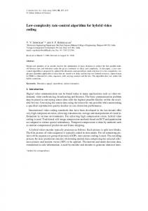
Figure 1. TSPEC element fields.
2.1 Referenced scheduler of IEEE 802.11e [2] The IEEE 802.11e draft provides an example scheduler in the annex as a reference design to meet the minimum performance requirements of different types of traffic. Each QoS station (QSTA) requiring strict and guaranteed QoS support can send an AddTraffic-Stream (ADDTS) frame to do QoS request with the HC. The QoS request frame includes a Traffic Specification (TSPEC) element (see Figure 1) that brings the information to notify the requirements of the traffic stream (TS). This simple scheduler uses the mandatory set of TSPEC parameters to generate a schedule; these parameters are Mean Data Rate, Nominal MSDU Size and Maximum Service Interval (MSI) or Delay Bound. If both MSI and Delay Bound are specified by the non-AP QSTA in the TSPEC, the scheduler uses the MSI to do calculation for the schedule. After gathering the requests, the QAP first determines the minimum value of all the MSI required by the admitted TSs. Then it will compute the highest sub-multiple of the beacon interval that is lower than the determined minimum of the MSI. This value will become the Scheduled Service Interval for all non-AP QSTAs with admitted streams. Therefore, the beacon interval is divided into multiple SIs and the admitted TS will be polled in a round-robin sequences during the CFP/CAP of each SI. To calculate the allocated TXOP of specified TS, the QAP uses the following parameters: Mean Data Rate ( ρ ), Nominal MSDU Size (L), the Scheduled Service Interval (SI) derived above, Physical Transmission Rate (R), Maximum allowable Size of
MSDU (M), and Overheads in time units (O). The Overheads in time is composed of IFS, ACKs and CFPolls duration. The TXOP is calculated as follows. First, the scheduler need to calculate the number of MSDUs reached during an SI.
⎡ SI × ρi ⎤ ⎥ ⎢ Li ⎥
Ni = ⎢
(1)
Then the scheduler calculates the TXOP duration to clear the generated MSDUs.
⎛ N i × Li
TXOPi = max ⎜
⎝
Ri
+ O,
M Ri
⎞
+ O⎟
⎠
(2)
If the application is strictly constant bit rate (CBR), then the data rate will always follow the value of the mean data rate. Thus the TXOP duration derived can fulfill the requirement of traffic streams of this kind. However, when the type of application becomes variable bit rate (VBR), the data rate and packet size may fluctuate with time. When the rate is much higher than the mean value, using this scheme may possibly increase the packet delay or drops and then it cannot provide guaranteed QoS for the admitted traffic streams.
3. Data rate estimation scheduling scheme If we estimate the possible TXOP duration only based on TSPEC parameters, as provided in referenced scheduler, QoS performance can be bad when the real rate is above mean value. Hence, under the inspiration from [9], we need a dynamical data rate estimating scheme with time to adjust the TXOP allocated to traffic streams of QSTAs. However, we estimate the mean data rate of a specified traffic over duration of service interval since the allocated TXOP aims to clear the traffic load that comes in a service interval. The duration of service interval is determined following the guideline of the referenced scheduler and [2]. Therefore, from the QoS requirements shown in [11], we suggest that the MSI of audio and that of real-time video be set to 25ms and 50ms, respectively. Then, we have to gather the queue length information at the beginning of current and the previous TXOP (in the previous service interval) for the TS and the amount of MSDU size belonging to the TS that are sent during previous TXOP. Before these terms are fully collected, the QAP temporarily uses the mean value from negotiated TSPEC parameters. Notice that only VBR traffic, whose values of Mean Data Rate and Peak Data Rate items of TSPEC are not the same, needs to do rate estimation. From the
following equation, we can have the total amount of traffic that comes in previous service interval:
Traffici = ∫ M i (t ) × dt = Li × ( S 2 − S1 )i + N (3) 0 SI
where the M i (t ) means the MSDU size coming on time t, L is the mean MSDU size, S 2 is the queue length at the beginning of TXOP of current SI, S1 is the queue length at the beginning of TXOP of previous SI, and the N here is the total amount of data size sent in TXOP. Then the mean application data rate of previous service interval can be written as: Traffici Rate i = (4) SI For the prediction of data rate of next SI, we use an AR-model equation. The equation is as following:
n ( n) = (1 − α ) Rate ( n) + α PreRate ( n) NextRate i i i
(5)
In the above equation, n is the index of service interval and α is an adjustable parameter. In order to reduce the complexity of calculations in hardware, we can choose α as 2 to the power of –k, where k is a n ( n) can be positive integer. In this way, NextRate i derived using bit-shift instead of multiplication. Having the new rate information, we can utilize it to predict the TXOP duration needed to be allocated. First we should estimate the corresponding number of packets belonging to traffic stream i:
n × SI ⎤ ⎡ NextRate i ⎥ M i ⎢ ⎥
N next , i = ⎢
(6)
Now, we derive the number of packets that will come in current service interval, and the traffic load should be cleared during next round of polling. The QAP then needs to calculate the required time corresponding to the number of traffic.
⎡ ⎣
⎛ M + 2 × SIFS + ACK ⎞ + O ⎤ ⎟ ⎥ ⎝R ⎠ ⎦
TXOP = ∑ N j , next ⋅ ⎜ ⎢ j
(7) Since the estimation may not always be very precise, we need a compensation mechanism to remedy the prediction error. The things we can utilize r are the remaining time T after allocating all the polled TXOP to QSTAs in the CAP/CFP duration and e the queue length information qi at the end of TXOP for traffic stream i. After collecting the queue length information, we do remaining time redistribution according to the weight which is derived from the e proportion of qi to the sum of all queue information:
⎛ e ⎞ , if ⎜ qsum = ∑ q j ⎟ > 0 T =T × qsum ∀j ⎝ ⎠ e
c
qi
r
(8)
i
This compensating time will also be combined with the TXOP allocated to QSTA to decrease the possible additional overheads of polling. In order to limit the long term average number of traffic that goes into the network, we add a token bucket mechanism to police the traffic. The depth of the token is set to the time to absorb the maximum burst size and the token adding rate is set to the mean data rate of the traffic stream. Hence, before allocating the polled TXOP, the QAP must examine the available token (will be transformed into available time) and the required time. Only when there is enough token in the bucket belonging to corresponding TS of the QTSA can the required time be fulfilled:
{
}
⎛ M + 2 × SIFS + ACK ⎞ + O + T c , token ⎟ j j ⎝R ⎠ (9) To implement the proposed scheme, the QAP should also maintain a polling list for all the admitted traffic streams of each QSTA and update the corresponding items when it receives the information: TXOP =
∑ min j
N j , next ⋅ ⎜
priority 6, VBR video trace derived from the VIC videoconferencing tool using H.261 coding of priority 5 [7], and CBR video of the lowest priority 4. Their specification parameters are as follows:
Figure 3. Traffic specification parameters Note that the MSI is set following the rule: MSI ≤ D − MTD . The parameter α that we use in −3 simulation is set to 2 . Hence the equation of data rate prediction can be written as: n ( n) = (1 − 2 −3 ) × Rate ( n) + 2 −3 × PreRate ( n). NextRate i i i The PHY (we use OFDM scheme parameters) and MAC parameters are as follows:
Figure 2. Polling list maintained by QAP.
4. Description of simulation 4.1. Simulation parameters The traffic we use in our simulation is composed of three types of applications: burst on/off audio stream of
Figure 4. PHY and MAC parameters
4.2. Simulation scenarios The scenario is composed of 6 QSTAs and a QAP. Each QSTA generates 3 streams to uplink to the QAP. Note that the implementation of referenced scheduler (HCCA/HCF) is from [7]. Our implementation is also adapted from it. The implementation constructs most
of the architecture of the IEEE 802.11e standard in the NS-2 code. We change the scheduling function to do queue and TXOP estimation. We will first simulate the proposed scheme using the parameters in Figure 3 and collect some data in Table 1 to show the performance comparison with other scheduling schemes. Then, we will evaluate the performance for various load condition using EDCA, HCCA (referenced scheduler), and our proposed scheme. In this scenario, the CBR MPEG flow plays the most important role in changing the load condition since it has the largest packet size. We will change the CFP load (the ratio of total required time to CFP duration in a service interval) by increasing or decreasing the MSDU size of CBR video traffic.
Figure 7. C.D.F. of packets vs. latency based on our scheme
Table 1. Performance of mean latency (in ms) for all schemes in scenario 1
Figure 5. Latency vs. time based on our scheme
Figure 6. Bandwidth vs. time based on our scheme
CBR audio
VBR video
CBR video
HCCA
10.395
304.539
13.132
Our Scheme
10.373
10.505
11.365
FHCF
10.428
11.101
11.722
The above figures show the performance of our scheme based on parameters in Figure 3. We only take one flow from each kind of traffic to be evaluated in the figures. We can find that the QoS requirements of all the TSs are fulfilled. The delays of all kinds of traffic are below 25ms. From Table 1, we can discover that our scheme has lower mean latency then others for all kinds of traffic. Regarding the following figures, while the delay of our scheme remains stable for different CFP load, HCCA (referenced scheduler) and EDCA cannot perform well under some conditions. As described, the referenced scheduler of HCCA cannot control the delay for VBR traffic in a reasonable range. For the EDCA scheme, when the load becomes heavier, the delay and the drop rate of packet for traffic of lower priority will both increase.
5. Conclusions
Figure 8. Mean delay of the audio flows vs. CFP load
Figure 9. Mean delay of the VBR video flows vs. CFP load
Aiming to provide bounded delay for both VBR and CBR traffic, we present a data rate estimation algorithm and a simple queue-length-based weighted compensating time allocation. From the performance evaluation, our scheme is good for both VBR and CBR traffic and is stable for various load conditions comparing with the referenced scheduling scheme and the contention-based access method. Comparing with FHCF scheme, we achieve equivalent performance in the same simulation scenario using, however, a scheme with lower complexity. Since the FHCF scheme uses an average of estimation error to do the adjustment of queue length estimation, when the VBR traffic fluctuates a lot around the mean value, like the traffic with bigger variance in data rate, it may not absorb the change that is much higher than average. As for our proposed scheme, we can successfully track the variation of data rate if the short time data rate variation is smooth. Besides, with the compensating method, we can easily remedy the estimation error to keep the good performance. Therefore, we provide a simple but efficient way to estimate fluctuating data rate and provide delay, packet loss rate, and throughput guarantee in errorfree wireless circumstance. If the channel condition is varying with time, our scheme needs to combine other techniques to lower the BER, like link adaptation. Finally, the polling-based scheme is much more suitable to operate under interference-free circumstance, while contention- based scheme can still operate normally when there are other WLANs within the range
6. References [1]
IEEE 802.11 WG: IEEE Standard 802.11-1999, Part 11: Wireless LAN MAC and Physical Layer Specifications. Reference number ISO/IEC 880211:1999(E), 1999.
[2]
IEEE 802.11 WG: IEEE 802.11e/D8.0, Wireless MAC and Physical Layer Specifications: MAC QoS Enhancements.
[3]
S. Mangold, S. Choi, G. R. Hiertz, et al, “Analysis of IEEE 802.11e for QoS Support in Wireless LANs”, IEEE Wireless Communications, Volume 10, Issue 6, Dec, 2003.
[4]
P. Garg, R. Doshi, R. Greene, et al, “Using IEEE
Figure 10. Mean delay of the CBR video flows vs. CFP load
802.11e MAC for QoS over Wireless”, Performance, Computing, and Communications Conference, 2003.
[5]
[6]
[7]
Q. Ni, L. Romdhani, and T. Turletti, “A Survey of QoS Enhancements for IEEE 802.11 Wireless LAN”, Journal of Wireless Communications and Mobile Computing, Wiley. 2004: Volume 4. P. Ansel, Q. Ni, and T. Turletti, "An Efficient Scheduling Scheme for IEEE 802.11e", WiOpt (Modeling and Optimization in Mobile, Ad Hoc and Wireless Networks),Cambridge, UK, March 2004. “HCF/FHCF NS-2 implementation”, http://wwwsop.inria.fr/rodeo/personnel/Ni.Qiang/fhcf/
[9] L. Yang, “P-HCCA: A New Scheme for
Real-time Traffic with QoS in IEEE 802.11e Based Networks”, in APAN Network Research Workshop, 2003.
[10] A. Annese, G. Boggia, P. Camarda, et al, “Providing Delay Guarantees in IEEE 802.11e Networks”, IEEE Proc. Vehicular Technology Conference 2004 Spring, Milan, Italy, May 2004.
[11] H. Fattah and C. Leung, “An Overview of Scheduling Algorithms in Wireless Multimedia Networks”, IEEE Wireless Communications, vol. 9, no. 5, pp. 76--83, Oct 2002.
[12] “HCF/EDCF NS-2 Stanford implementation”, http://nondot.org/~radoshi/cs444n/
[8]
A. Grilo, M. Macedo, and M. Nunes, “A Scheduling Algorithm for QoS Support in IEEE 802.11e Networks”, IEEE Wireless Communications, June 2003.
[13] The Network Simulator ns-2. http://www.isi.edu/nsnam/ns