the number of operations executed by the tasks accessing the buffer (two in this ... The execution of all buffer operations is charged to the ..... Berkshire UK, 1992.
From UML descriptions of high-level software architecture to LQN performance models Dorina C. Petriu and Xin Wang Carleton University Ottawa, Canada, K1S 5B6 e-mail: {petriu|xinw}@sce.carleton.ca
Abstract. Performance characteristics, such as response time and throughput, play an important role in defining the quality of software products, especially in the case of real-time and distributed systems. The developers of such systems should be able to assess and understand the performance effects of various architectural decisions, starting at an early stage, when changes are easy and less expensive, and continuing throughout the software life cycle. This can be achieved by constructing and analyzing quantitative performance models that capture the interactions between the main system components and point to the system’s performance trouble spots. The paper proposes a formal approach to building Layered Queueing Network (LQN) performance models from UML descriptions of the high-level architecture of a system, and more exactly from the architectural patterns used in the system. The performance modelling formalism, LQN, is an extension of the well-known Queueing Network modelling technique. The transformation from UML architectural description of a given system to its LQN model is based on PROGRES, a well known visual language and environment for programming with graph rewriting systems.
1. Introduction Performance characteristics, such as response time and throughput, play an important role in defining the quality of software products, especially in the case of real-time and distributed systems. There is a growing body of research that studies the role of software architecture in determining software quality in general [2], [17], and performance characteristics in special [21], [22]. Since architectural decisions are made very early in the software development process, it would be helpful to be able to assess their effect on software performance as soon as possible. Software Performance Engineering (SPE) is a technique introduced in [19] that proposes to use quantitative methods and performance models in order to assess the performance effects of different design and implementation alternatives during the development of a system. SPE promotes the idea that the integration of performance analysis into the software development process, from the earliest stages to the end, can insure that the system will meet its performance objectives. This would eliminate the need for “late-fixing” of performance problems, a frequent practical approach that postpones any performance concerns until the system is completely implemented. Late fixes tend to be very expensive and inefficient, and the product may never reach its original requirements. Although the need for SPE is recognized by industry, there are many barriers that prevent its wide adoption [9]. Some of these barriers are technical, other related to management issues. One of the technical problems is the existence of a cognitive gap between the software and the performance domains. Software developers are concerned with designing, implementing and testing the software, but they are not trained in performance modelling and analysis techniques. The software development teams depend usually on specialized performance groups to do the performance evaluation work, which leads to additional communication delays, inconsistencies between design and model versions and late feedback. This paper contributes toward bridging the gap between software architecture and performance analysis. It proposes a systematic approach, based on graph transformations, to
build LQN performance models from UML description of high-level software architecture of a system. The high-level architecture describes the main system components and their interactions at a level of abstraction that captures certain characteristics relevant to performance, such as concurrency, parallelism, contention for software resources (as software servers and critical sections), synchronization, serialization, etc. This paper is a development of previous work by the same authors [12], where an “ad-hoc” language for architectural descriptions was used instead of UML [3]. UML is attractive because it is a standard, and is rapidly gaining acceptance in the software industry. However, UML is a very rich, sometime informal language, which raises a number of yet unresolved issues. This paper is but a step in a longer research effort, whose final objective is to implement the proposed model-building technique in a tool (most probably in connection with a UML-based CASE tool). By automating the construction of the performance models from software architectures, the time and effort required for SPE will be considerably reduced, and the consistency between the model and the system under development more easily maintained. Such a model will be solved with existing performance analysis tools, producing much faster feedback for the software development team. Frequently used architectural solutions are identified in literature as architectural patterns (such as pipeline and filters, client/server, client/broker/server, layers, master-slave, blackboard, etc.) [4], [18]. A pattern introduces a higher-level of abstraction design artifact by describing a specific type of collaboration between a set of prototypical components playing well defined roles, and helps our understanding of complex systems. The paper defines graph transformations from a number of frequently used architectural patterns into LQN sub-models. The formalism used for building performance models is the Layered Queueing Network (LQN) model [23, 24, 13], an extension of the well known Queueing Network model. LQN was developed especially for modelling concurrent and/or distributed software systems. Some LQN components represent software processes, others hardware devices. LQN determines the delays due to contention, synchronization and serialization at both software and hardware levels (see section 3 for a more detailed description). LQN was applied to a number of concrete industrial systems (such as database applications [6], web server [8], telecommunication system [20], etc.) and was proven useful for providing insights into performance limitations at software and hardware levels. The paper is organized as follows: architectural patterns and their representation as UML collaborations are discussed in section 2, a short description of the LQN model is given in section 3, transformation of a few frequently utilized architectural patterns into LQN is presented in section 4, the PROGRES graph schema and the principles for graph transformations are given in section 5, a case-study telecommunication system is presented in section 6 and conclusions in section 7. 2. Architectural Patterns and UML Collaborations According to [2], a software architecture represents a collection of computational components that perform certain functions, together with a collection of connectors that describe the interactions between components. A component type is described by a specification defining its functions, and a set of ports representing logical points of interaction between the component and its environment. A connector type is defined by a set of roles explaining the expected behaviour of the interacting parties, and a glue specification showing how the interactions are coordinated. 2
1..n
client
client Client
fwd-broker
server
req_service_k() service_k()
Client Server Broker
FWD_BROKER
Broker
serve other requests
fwd-broker
reply() return Server
server ... service_k( ) ...
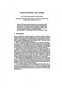
Figure 1. UML collaboration for the forwarding broker pattern
A similar, even though less formal, view of a software architecture is described in the form of architectural patterns [4, 18] which identify frequently used architectural solutions, such as pipeline and filters, client/server, client/broker/server, master-slave, blackboard, etc. Each architectural pattern describes two inter-related aspects: its structure (what are the components) and behaviour (how they interact). In the case of high-level architectural patterns, the components are usually concurrent entities that execute in different threads of control, compete for resources, and may require synchronization. Concurrency aspects contribute to system performance, and therefore must be captured in a performance model. The paper proposes to use high-level architectural patterns as a basis for translating software architecture into performance models. A subset of frequently used patterns (some of which are later used in a case study) are described in this section in the form of UML collaborations (not to be confused with UML collaboration diagrams, a type of interaction diagrams) [3]. According to the authors of UML, a collaboration is a notation for describing a mechanism or pattern, which represents “a society of classes, interface, and other elements that work together to provide some cooperative behaviour that is bigger than the sum of all of its parts.” A collaboration has two aspects: structural (usually represented by a class/object diagram) and behavioural (an interaction diagram). Collaborations can be used to hide details that are irrelevant at a certain level of abstraction; these details can be observed by “zooming” into the collaboration. The symbol for collaboration is an ellipse with dashed lines, and may have an “embedded” square showing template classes. Another special UML notation employed in this section is that of an active class (object) which has its own thread of control, represented by a square with thick lines. An active object may be implemented either as a process (identified by the stereotype ), or as a thread. The literature identifies a relatively small number of patterns used for high-level architecture [4, 18]. The following patterns are discussed in the paper: pipeline and filters, client/server (with and without CORBA interface), and critical section. The pipeline and filters pattern divides the overall processing task into a number of sequential stages, which are implemented as filters connected by unidirectional pipes. We are interested here in active filters [4] that are running concurrently. Each filter is implemented as an active object that loops through the following steps: “pulls” the data from the preceding pipe, processes it, and “pushes” the results down the pipeline. The way in which the pipelines are implemented may have performance consequences, as discussed in section 4, and shown in Figures 5 and 6. 3
1..n
client
client
server
hfw-broker
Client req_service_k() service_k()
Client Server Broker
HFW_BROKER
Broker
hfw -broker
serve other requests reply()
Server
server ... service_k( ) ...
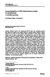
Figure 2. UML collaboration for the half-forwarding broker pattern
The Client-Server pattern is one of the most frequently used in today’s distributed systems, especially since the introduction of new midware technology such as CORBA [11], which facilitates the connection between clients and servers running on heterogeneous platforms across local or wide-area networks. The communication between client and servers may have an important effect on performance, for which reason different alternatives are considered in the paper: direct client/server communication through a synchronous message and three types of connections mediated by brokers. Fig. 1 shows the UML collaboration for the forwarding broker pattern [1], where the broker relays a client’s request to the relevant server, retrieves the response from the server and relays it back to the client. (When relevant, the “object flow” carried by a message is represented by a little arrow with a circle, while the message itself is an arrow without circle. A synchronous message implies a reply, therefore can carry objects in both directions). The forwarding broker is at the center of all communication paths between clients and servers, and can provide load balancing or restart centrally any failed transactions. However, there is a price to pay in terms of performance: a client-server interaction requires four messages, which leads to excessive network traffic when the client, broker and server reside on different nodes. An alternative that reduces the network traffic is the half-forwarding broker [1] from 1 ..n
client
client
hd-broker
Client get_handle() Client Server Broker
HD_BROKER
Broker
service_k()
hd-broker
return Server
server ... service_k( ) ...
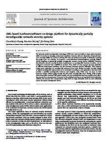
Figure 3. UML collaboration for the handle-driven broker pattern
4
server
Fig.2, where the server returns the reply directly to the client. This reduces the number of messages for a client/server interaction to three, while it retains the main advantages of the forwarding broker (load balancing and centralized recovery from failure). A handle-driven [1] broker (as in Fig.3) returns to the client a handle containing all the information required to communicate directly with the server. The client may use this handle to talk directly to the server many times, thus reducing the potential for performance degradation. However, the client takes on additional responsibilities, such as checking if the handle is still valid after a while, and recovering from failures. Load balancing is also more difficult in this case. The critical section pattern applies to cases where two or more active objects share the same passive object. The constraint {sequential} attached to the methods of the shared object indicates that the callers must coordinate outside the shared object (for example, by the means of a semaphore) to insure correct behaviour. Such a synchronization introduces performance delays, and it is represented in the performance model as shown in section 4, Figure 12. 3. LQN Model In order for the paper to be self-contained, a brief description of the LQN modelling technique is given in this section. LQN was developed as an extension of the well-known Queueing Network (QN) model, at first independently in [23, 24] and [13], then as a joint effort [5, 6]. The LQN toolset presented in [5] includes both simulation as well as analytical solvers that merge the best previous approaches. The main difference with respect to QN is that in LQN a server may become a client to other servers while serving its own clients. An LQN model is represented as an acyclic graph whose nodes are software entities and hardware devices, and whose arcs denote service requests. The software entities (named also tasks) are drawn as parallelograms, and the hardware devices as circles. Different nodes play the roles of clients (only outgoing arcs), intermediate servers (both incoming and outgoing arcs) and pure servers (only incoming arcs). The last usually represent hardware resources (such as processors, I/O devices, communication network, etc.) Figure 4 shows a simple example of an LQN model for a three-tiered client/server system: at the top there are two groups of stochastic identical clients. Each client sends requests for a certain service offered by Application task, which represents the business layer of the system. Every kind of service offered by an LQN task is modelled by a task entry, drawn as a parallelogram “slice”. An entry has its own execution times and demands for other services (given as model parameters). Client_1 Client_2 In this case, each Application entry requires services from two different Database entries. Proc1 Proc2 The Database can process several requests concurrently, reason for which is modelled as a Application multi-server (i.e., a set of identical servers sharing a common queue). Each multi-server replication models a “virtual” thread that serves Database a request at a time. (Virtual threads may be Proc3 implemented either as software threads of the same process, or as a set of identical processes Disk1 Disk2 that are serving requests from a common queue). Every software task is running on a given Figure 4. Simple LQN model processor shown as a circle; more than one task can share the same processor. The word layered 5
in the name LQN does not imply a strict layering: a task may call other tasks in the same layer, or skip over layers. All the arcs used in this example represent synchronous requests, where the sender of a request message is blocked until it receives a reply from the provider of service. It is possible to have also asynchronous request messages, where the sender doesn’t block after sending a request, and the server doesn’t reply. Although not explicitly illustrated in the LQN notation, each server has an implicit message queue where the incoming requests are waiting their turn to be served. Servers with more than one entry still have a single input queue, where requests for different entries wait together. The default scheduling policy of the queue is FIFO, but other policies are also supported. Typical results of an LQN model are response times, throughput, utilization of servers on behalf of different types of requests, and queueing delays. LQN was applied to different applications (such as databases [6], telecommunication systems [8, 20]). The model results help to identify software and/or hardware bottlenecks [10] that limit the system performance under different workloads and resource allocations. UpStreamFilter DownStreamFilter PIPELINE WITH MESSAGE
filter1
DownStreamFilter
UpStreamFilter
filter2
filter1
filter2
Figure 5. Transformation of the Pipeline with Message UpStreamFilter DownStreamFilter
PIPELINE Buffer WITH BUFFER
UpStreamFilter >
buffer
filter1 push()
filter1
DownStreamFilter
Buffer 1 ..n
push() {sequential} pull() {sequential}
1 ..n
>
filter2 pull()
filter1
filter2
filter2 semaphore
push
pull
semaphore and buffer
proc
a) All the filters are running on the same processor node
proc1
push
pull
b) The filters are running on different processor nodes
Figure 6. Transformation of the Pipeline with buffer
6
proc2
4. Transformations of architectural patterns into LQN A software system contains many components involved in various architectural connection instances (each described by a pattern/collaboration), and a component may play different roles in different patterns. The transformation of the architecture into a performance model is done in a systematic way, pattern by pattern. As expected, the performance of the system depends on the performance attributes of its components and on their interaction. Performance attributes are not central to the software architecture itself, but must be specified by the user in order to transform the architecture into a performance model. Such attributes describe the demands for hardware resources by the software components: allocation of processes to processors, average execution time for each software component, average demands for other resources such as I/O devices, communication networks, etc. Pipeline and Filters. Figures 5 and 6 shows the translation of different versions of this pattern, the first using asynchronous messages for the pipeline, and the other a shared buffer. Each active filter becomes an LQN software server whose service time includes the processing time of the filter. The pipeline connector is modelled as an asynchronous LQN message in Fig. 5. The CPU times for send/receive system calls are added to the service times of the two LQN tasks, respectively. A network delay for the message can be represented in LQN as a delay attached to the arc. In the case of a pipeline with buffer, an asynchronous LQN arc is still required , but this does not take into account the serialization delay due to the constraint that buffer operations must be mutually exclusive. A third task will enforce this constraint. It has as many entries as the number of operations executed by the tasks accessing the buffer (two in this case, “push” and “pull”). In Fig. 6, exactly the same architectural pattern has two LQN counterparts, due to a difference in processor allocation. The execution of all buffer operations is charged to the same processor node in Fig. 6a, and to different processor nodes in Fig.6b. Fig. 7 represents the transformation for the so-called “double filter” collaboration, that can be used either in conjunction with a “pipeline with message”, or a “pipeline with buffer”, as seen in the case-study from section 6. (This collaboration can be generalized for any type of active objects that are sharing the same execution thread.) It describes the case of two nonconsecutive filters that are running in the same process (i.e., share the same execution thread). The LQN model captures the contention of the two buffer objects for the same execution thread. Since the LQN version used for this paper didn’t accept cyclic graphs for reasons related to deadlock prevention, we represented each passive object filter as a LQN “dummy” task, therefore treating it as an active object. In order to prevent the dummy tasks from executing simultaneously, a third "executive" task serializes the first two. All filter’s processing is charged to the “executive” task entries. The dummy tasks don’t do any real
Filter Filter Container
dummyUpStrm
DOUBLE FILTER
...
dummyDnStrm
container
Container Filter Filter
doubleFilter
... ...
upStrm dnStrm
upStrm
...
downStrm
...
proc dummy proc
Figure 7. Transformation of the Double Filter Collaboration
7
Client Server CLIENT SERVER
Client
Client 1..n
client1
client2
1..n
client2
client1 service2 () Server
service1()
service1 service2
service2 ()
server
server
service1() service2()
Figure 8. Transformation of the Client-Server pattern with a direct connection
work, and are waiting instead for the executive task to do the work on their behalf. They are allocated on a dummy processor (not to interfere with the scheduling of the “real” processor node). Client-Server patterns. Fig. 8 shows the transformation to LQN of a direct client/server connection through a synchronous communication (rendezvous), where the client sends a request to the server and blocks until the reply from the server comes back. A server may offer a wide range of services (represented here as the server’s object methods) each one with its own performance attributes (execution time and number of visits to other servers). A client may invoke more than one of these services at different times. As in the pipeline connection case, the CPU time required to execute the system call for send/receive/reply are added to the service times of the corresponding tasks. The allocation of tasks to processors is not shown in Fig. 8, because the transformation does not depend on it (each LQN task is allocated exactly as its architectural component counterpart). Software developers of client-server systems are mostly interested in the components that are part of their application, and less in the details of the underlying midware, operating system or networking software. The use of UML collaborations comes in handy, because it allows us to hide unnecessary details. For example, client/server applications using a CORBA interface do not have to show explicitly the “broker” component in their architecture (as it is not part of the software application). Instead, a collaboration (such as those defined in Fig. 1, 2, and 3) can be used to indicate the type of desired client/server connection. However, the performance model will represent explicitly the broker and it’s interaction with the client and server counterparts. Figures 9, 10 and 11 illustrate the transformation of three client-server connections through different kinds of CORBA interfaces. The connections have similar architectural descriptions, differentiated only by the kind of UML collaboration used. However, their LQN models are quite different, as the connections have very different operating modes and performance characteristics. The forwarding broker (Fig.9) is modelled as an LQN multiserver with as many entries as server entries. Each task replication models a “virtual” thread of the broker. A thread accepts a client’s request, passes it on to the server, then remains blocked waiting for the server’s reply to come back and to relay it to the client. During the time a thread is blocked, other threads get to run on the CPU on behalf of other requests. Therefore, the multi-server models in this case a singer broker that can serve concurrently more than one request. 8
Client Server Broker
client1
FWD_BROKER
Client
client2
Client
>
1..n
>
1..n
forwarding broker
client2
client1 service2 () Server
service1()
service2 ()
server service1 service2
service1() service2()
server
Figure 9. Transformation of the Client-Server pattern with Forwarding Broker
Client Server Broker
HFW_BROKER
client2
Client
Client
client1
1 ..n
1..n
halfforwarding broker
client2
client1 service2 () service1()
Server
service2 ()
server service1 service2
service1() service2()
server
Figure 10. Transformation of the Client-Server pattern with Half-Forwarding Broker Client Server Broker
HD_BROKER
Client
client1
Client
1..n
client2
1..n
client1
client2 service2 ()
service1()
Server
service2 ()
handle-driven broker
server
service1 service2
server
service1() service2()
Figure 11. Transformation of the Client-Server pattern with Handle-Driven Broker
The half-forwarding broker model (Fig.10) uses LQN forwarding arcs (drawn with dotted lines) which have a special semantic. After accepting a request from a client, the acceptor task will do some processing, then will forward the request to another task. The forwarder is free to continue its activity, while the client remains blocked, waiting for the reply. The second task that continues to serve the request may eventually complete it and send the reply directly back to the client, or may decide to forward the request to another task. The LQN 9
Accessor Shared CRITICAL SECTION
Accessor user1
f1 ()
Accessor
... Shared
userN
fN ()
shared f1() {sequential} f2() {sequential} ... fN() {sequential}
...
user1 user1
...
userN
userN
semaphore 1
2 ... N
semaphore and f1 f2 . . . fN critical sections f1
...
fN
proc proc1 a) All the users are running on the same processor node
procN
b) The users are running on different processor nodes
Figure 12. Transformation of the Critical section collaboration
semantic implies that a reply will be sent to the client by the last task in the forwarding chain (but the reply is not represented as an arc in the model). In Figure 10, the broker is the task that receives the requests from the clients and forwards them to the appropriate entry of the server. The broker must have a separate entry for each entry it forwards to, otherwise the clients would be unable to choose the server entry they need. Figure 11 represents the LQN model for the handle-driven broker that sends two separate messages for each client request: one to the broker for getting the handle, the other directly to the desired server entry. Since the broker does the same kind of work for all the requests no matter what server entry they need, the broker may be have a single entry in this case. Critical Section. The transformation of the critical section collaboration produces either the model given in Fig. 12a or 12b, depending on the allocation of user processes to processor nodes (similar to the pipeline case). The premise is that an LQN task cannot change its processor node. Since the operations on the shared object (i.e., critical sections) may be executed by different threads of controls of different users running on different processors, each operation is modelled as an entry that belongs to a different task f1 to fN running on its user’s node. However, these tasks must be prevented from running simultaneously, reason for 10
which the semaphore task was introduced. The performance attributes to be provided for each user must specify critical and non-critical execution times separately. 5. Graph schema and transformation approach The graph schema defined according to the PROGRES language [14 to 16] is presented in Figure 13. The upper part of the figure contains the input schema for architectural descriptions and the lower part the output schema for LQN models (light-gray nodes). The input schema does not capture all the richness of UML, but only those elements that are necessary for converting a high-level architecture into an LQN model. The advantage of basing the transformation on architectural patterns expressed by UML collaborations is that Forwarding Broker Half-forwarding Broker
Pipeline with Buffer
Handle-driven Broker
Pipeline with Message
Direct Client-Server CriticalSection
DoubleFilter container
shared
filter
accessor
PIPELINE & FILTERS upStrmFilter downStrmFilter
client
CLIENT_SERVER
server broker NonShared
Shared
Active Device Processor
contains PASSIVE
string[0::n] string
COLLABORATION
has
Multiplicity
ExecTime
invokes
OBJECT
OPERATION
real
Constraint
string
integer link
OP_ENTRY
NODE
OBJ_TASK
Name
integer
Multiplicity
ServiceTimes
owns
string
real Entry
Task out out
uses real integer
in
in in out
SeviceTime Device
Sync
Forward
Async
Multiplicity
NbVisits ARC_PARAM
Figure 13. Joint graph schema for architectural patterns and LQN models 11
real
such higher-level of abstraction artifacts greatly simplify the graph schema and the transformation process. The disadvantage is that these artifacts have to be pre-identified and represented in the schema and by the transformation rules, which limits the extendibility of the transformation process. This disadvantage is somehow mitigated by the fact that the number of high-level architectural patterns is relatively small. In order to accommodate graphs in intermediary translation stages, the two schemas are joined together by three nodes shown in dark-gray at the base of the node class hierarchy (NODE, OBJ_TASK, and OP_ENTRY). The collaborations nodes representing architectural patterns make up a big part of the input schema. Inheritance is useful for classifying the different patterns and their variants. “Role” edges connect the collaboration nodes to the architectural component nodes, which are active and passive objects, their operations and links. The output schema reflects closely the LQN graph notation presented in section 3. The node types are “task”, “device” and “entry”. The LQN arcs may represent three types of requests (synchronous, asynchronous and forwarding); a parameter indicates the average number of visits associated with each request. Since PROGRES edges cannot have attributes, we represent an LQN arc by three elements: an incoming edge, a node carrying the parameter and an outgoing edge. Graph transformation rules have been defined for each architectural pattern, following closely the transformations shown in Fig 5 through 12. A PROGRES transaction is executed for every architectural pattern found in the input architectural description graph. The translation process ends when all the patterns have been processed. The final result is an LQN model that can be written to a file according to a predefined LQN model format [5]. The following translation approach was followed: · The collaboration nodes do not have an LQN equivalent. · Each architectural component (i.e., object) is converted to an LQN task, for which reason a common base class OBJ_TASK was defined in the graph schema. However, the correspondence between components and tasks is not bijective, as in some cases a single object may generate more than one task for the following reasons: to charge correctly the execution times to various processors (Fig. 6.b and 12.b), or to model processes that are not part of the application, but of the underlying midware (such as brokers in Fig. 9 -11). · Object operations are usually converted into an LQN entry, with some exceptions as in Fig. 6.b and 12.b, when an operation is converted into an entry and a task. · Processes and devices, which are attributes in the architectural view, become full-fledged nodes in LQN. This happens because the issue of resource allocation is secondary to the software development process, but is central to performance analysis. 6. Case-study: a Telecommunication System This section presents the architecture of an existing telecommunication system which is responsible for developing, provisioning and maintaining various intelligent network services, as well as for accepting and processing real-time requests for these services (see Fig. 14). The system was modelled in LQN, and its performance analysed in [20]. Here we consider only the transformation from the system’s UML architecture to its LQN model. The real time scenario modelled in [20] starts from the moment a request arrives to the system and ends after the service was completely processed and a reply was sent back. As shown in Figure 14, a request is passed through several filters of a pipeline: from Stack process to IO process to RequestHandler and all the way back. The main processing is done by the RequestHandler, which accesses a real-time database to fetch an execution "script" for the 12
DoubleFilter FirstFilter ScndFilter
DoubleFilter FirstFilter ScndFilter
DOUBLE FILTER
DOUBLE FILTER UpStrmFilter DownStrmFilter PIPELINE Buffer
UpStrmFilter DownStrmFilter
PIPELINE WITH MESSAGE
WITH BUFFER
Stack
IO
StackIn
IOin
inBuffer
StackOut
IOout
outBuffer
UpStrmFilter DownStrmFilter
PIPELINE WITH MESSAGE
doubleBuffer 1..n
RequestHandler
UpStrmFilter DownStrmFilter PIPELINE Buffer
Client Server
CLIENT SERVER
WITH BUFFER
ShMem1
ShMem2
alloc() {sequential} free() {sequential}
update() {sequential}
DataBase
Accessor Shared
Accessor Shared
CRITICAL SECTION
CRITICAL SECTION
Figure 14. UML description of the high-level architecture of a telecommunication system
desired service, then executes the steps of the script accordingly. The script may vary in size and types of operations involved, and hence the workload varies largely from one type of service to another (by one or two orders of magnitude). Due to experience and intuition, the designers decided from the beginning to allow for multiple replications of the RequestHandler process in order to speed up the system. Two shared objects, ShMem1 and ShMem2, are used by the multiple RequestHandler replications. The system was meant to run either on a single-processor or on a multi-processor with shared memory. Processor scheduling is such that any process can run on any free processor (i.e., the processors were not dedicated to specific tasks). Figure 15 shows the LQN model of the system obtained by applying the graph transformations proposed in the paper. The performance analysis of the model is presented in [20] and is, unfortunately, beyond the scope of this paper. The model was solved with existing LQN solvers [5], and the highest achievable throughput was found for different loads and configurations. The analysis has also exposed some weaknesses in the original software architecture due to excessive serialization at the IO process and the double buffer, which starts showing up when more processing capacity is added to the system. After removing the serialization constraints, a new software bottleneck emerges at the database, which leads to the conclusion that the software architecture does not scale up well [20]. The study illustrates the usefulness of applying performance modelling and analysis to software architectures.
13
7. Conclusion The main challenge for the automatic generation of LQN performance models from software architecture descriptions stems from the fact that the two views have different semantic, purpose and focus, which must be bridged by the translation process. The architectural view represents only the software components of the application under development, and may hide operating system and midware services that must be represented in the performance model. On the other hand, many details of the architecture are irrelevant to the performance model. The issue of resource allocation and resource demands represents another important discrepancy between the two views. Another challenge is dealing with the richness of the UML language. This paper is only a step in a longer research effort which aims to bridge the gap between software architecture and performance modelling. So far, the graph rewriting formalisms has proven very useful in dealing with these challenges.
l
StackIn
IOin Request Handler
Dummy Proc StackOut
StackExec
IOout
IOexec
update
DataBase
ShMem2 pull
push
Buffer
alloc
free
ShMem1 Proc
Figure 15. LQN model of the telecommunication system
8. References [1] [2] [3] [4] [5]
[6]
O. Adebayo, J. Neilson, D. Petriu, “A Performance Study of Client-Broker-Server Systems”, in Proceedings of CASCON’97, pp 116-130, Toronto, Canada, November 1997. R.Allen, D. Garlan, “A Formal Basis for Architectural Connection”, ACM Transactions on Software Engineering Methodology, Vol.6, No.3, pp 213-249, July 1997. G.Booch, J.Rumbaugh, I.Jacobson, The Unified Modeling Language User Guide, AddisonWesley, 1999. F. Buchmann, R. Meunier, H. Rohnert, P. Sommerland, M. Stal, Pattern-Oriented Software Architecture: A System of Patterns, Wiley Computer Publishing, 1996. G. Franks, A. Hubbard, S. .Majumdar, D. Petriu, J. Rolia, C.M. Woodside, “A toolset for Performance Engineering and Software Design of Client-Server Systems”, Performance Evaluation, Vol. 24, Nb. 1-2, pp 117-135, November 1995. G. Franks, S. Majumdar, J. Neilson, D. Petriu, J. Rolia, C.M. Woodside. "Performance Analysis of Distributed Server Systems". In Proceedings of the 6th International Conference on Software Quality, pp. 15-26, Ottawa, Canada, October 1996. 14
[7]
[8]
[9] [10]
[11]
[12]
[13] [14] [15]
[16] [17] [18] [19] [20]
[21] [22]
[23]
G. Franks, C.M.Woodside, “Performance of Multi-Level Client-Server Systems with Parallel Service Operations”, Proceedings of the First International Workshop on Software and Performance, Santa Fe, USA, pp.120-130, Oct. 1998. J.Dilley, R.Friedich, T.Jin, J.Rolia, "Measuremnt Tool and Modelling Techniques for Evaluating Web Server Performance" in Lectures Notes in Computer Science, vol.1245, Springer, pp.155-168, R.Marie, B.Plateau, M.Calzarosa, G.Rubino (eds), Proc. of 9-th Int. Conference on Modelling Techniques and Tools for Performance Evaluation, June 1997. Mary Hesselgrage, “Avoiding the Software Performance Crisis”, Proc. of the First International Workshop on Software and Performance, Santa Fe, USA, pp.78-79, Oct.1998. J.E.Neilson, C.M.Woodside, D. Petriu, and S. Majumdar, "Software bottlenecking in clientserver systems and rendezvous networks", IEEE Transactions on Software Engineering, vol. 21(19) pp.776-782, September 1995. Object Management Group, The Common Object Request Broker: Architecture and Specification, Object Management Group and X/Open, Framingham, MA and Reading Berkshire UK, 1992. D. Petriu, X.Wang, “Deriving Software Performance Models from Architectural Patterns by Graph Transformations”, Proc. of the Sixth International Workshop on Theory and Applications of Graph Transformations TAGT’98, Paderborn, Germany, Nov. 1998. J.A. Rolia, K.C. Sevcik, “The Method of Layers”, IEEE Trans. On Software Engineering, Vol. 21, Nb. 8, pp 689-700, August 1995. A. Schuerr, “PROGRES: A Visual Language and Environment for PROgramming with Graph Rewrite Systems”, Technical Report AIB 94-11, RWTH Aachen, Germany, 1994. A. Schuerr, “Introduction to PROGRES, an attribute graph grammar based specification language”, in Graph-Theoretic Concepts in Computer Science, M. Nagl (ed), Vol. 411 of Lecture Notes in Computer Science, pp 151-165, 1990. A. Schuerr, “Programmed Graph Replacement Systems”, in Handbook of Graph Grammars and Computing by Graph Transformation, G. Rozenberg (ed), pp 479-546, 1997. M. Shaw, D. Garlan, Software Architectures: Perspectives on an Emerging Discipline, Prentice Hall, 1996. M. Shaw, “Some Patterns for Software Architecture” in Pattern Languages of Program Design 2 (J.Vlissides, J. Coplien, and N. Kerth eds.), pp.255-269, Addison Wesley, 1996. C.U. Smith, Performance Engineering of Software Systems, Addison Wesley, 1990. C.Shousha, D.C. Petriu, A. Jalnapurkar, K.Ngo, “Applying Performance Modelling to a Telecommunication System”, Proceedings of the First International Workshop on Software and Performance, Santa Fe, USA, pp.1-6, Oct.1998. B.Spitznagel, D.Garlan, “Architecture-Based Performance Analysis”, Proc. of the Int. Conference on Software Eng. and Knowledge Eng. SEKE’98, pp. 146-151, 1998. L.G Williams, C.U.Smith, “Performance Evaluation of Software Architectures”, Proceedings of the First International Workshop on Software and Performance, Santa Fe, USA, pp.164-177, Oct. 1998. C.M. Woodside. "Throughput Calculation for Basic Stochastic Rendezvous Networks". Performance Evaluation, vol.9(2), pp. 143-160, April 1988.
[24] C.M. Woodside, J.E. Neilson, D.C. Petriu, S. Majumdar, “The Stochastic Rendezvous Network Model for Performance of Synchronous Client-Server-like Distributed Software”, IEEE Transactions on Computers, Vol.44, Nb.1, pp 20-34, January 1995.
15