silicon mold wafer. Upon release, the actuators are assembled onto a target wafer using a solder bond. The solder-bonding process will provide easy integration ...
JOURNAL OF MICROELECTROMECHANICAL SYSTEMS, VOL. 7, NO. 2, JUNE 1998
141
Design and Fabrication of an Angular Microactuator for Magnetic Disk Drives David A. Horsley, Michael B. Cohn, Angad Singh, Roberto Horowitz, and Albert P. Pisano
Abstract— Angular electrostatic microactuators suitable for use in a two-stage servo system for magnetic disk drives have been fabricated from molded chemical-vapor-deposited (CVD) polysilicon using the HexSil process. A 2.6-mm-diameter device has been shown to be capable of positioning the read/write elements of a 30% picoslider over a 6 1-�m range, with a predicted bandwidth of 2 kHz. The structures are formed by depositing polysilicon via CVD into deep trenches etched into a silicon mold wafer. Upon release, the actuators are assembled onto a target wafer using a solder bond. The solder-bonding process will provide easy integration of mechanical structures with integrated circuits, allowing separate optimization of the circuit and structure fabrication processes. An advantage of HexSil is that once the mold wafer has undergone the initial plasma etching, it may be reused for subsequent polysilicon depositions, amortizing the cost of the deep-trench etching over many structural runs and thereby significantly reducing the cost of finished actuators. Furthermore, 100-�m-high structures may be made from a 3-�m deposition of polysilicon, increasing overall fabrication speed. [256] Index Terms—Disk drive, electrostatic actuator, HexSil, microfabrication, polysilicon, servo control.
I. INTRODUCTION
T
HE AREAL density of magnetic disk drives is increasing at an annual rate of 60% and is expected to reach 10 Gb/in by the turn of the century [1]. Until recently, these increases have been achieved by a combination of increased track density—which is the number of tracks per inch along the radius of the disk—and an increase in linear bit density—which is the number of bits written along one inch of a track. Increases in bit density require either more sensitive head elements or reduced flying height. Tribological problems posed by contact and near-contact recording have been delayed by the introduction of magnetoresistive (MR) heads, which allow higher flying heights due to their greater sensitivity compared to inductive elements. However, given that current bit densities are approximately ten times greater than track densities, significant areal density increases can be achieved by reducing the track width without reducing flying height or resorting to giant magnetoresistive (GMR) heads. To achieve the goal of 10 Gb/in , the data track density is expected to reach 25 000 tracks per inch, resulting in tracks which are 1 m wide and an allowable servo tracking accuracy of 100 nm at bandwidths of 2 kHz or greater. Manuscript received February 25, 1997. Subject Editor, H. Fujita. This work was supported by DARPA under Contract DABT63-95-C-0028. The authors are with the Berkley Sensor and Actuator Center, University of California, Berkeley, CA 94720 USA. Publisher Item Identifier S 1057-7157(98)03887-6.
Because conventional servo actuators cannot provide this level of tracking accuracy, the use of a microactuator for highbandwidth high-accuracy positioning has been proposed. To date, these designs have been of three distinct types. The first type may be classified as an actuated suspension. In this approach, conventional assembly and machining techniques are used to integrate an electromagnetic or piezoelectric actuator into a conventional steel suspension [2], [3]. A disadvantage to these designs is that they locate the actuator far from the read/write elements and therefore have a limited bandwidth due to suspension vibration. The second type may be classified as an actuated head in which the actuator is located on the slider and the read/write elements are placed on top of the actuator [4], [5]. The critical limitation of this approach is that the actuator fabrication process must be compatible with the head/slider fabrication process. The actuators discussed in this paper are of the third type, where the actuator is placed between the slider and the gimbal of a conventional suspension [6], [7]. In contrast to competing electroplated metal actuators, the devices described in this paper have the advantage of being fabricated from polysilicon, which fails at a fracture strength which is roughly an order of magnitude greater than the 0.2% yield strength of a typical metal [8]. A. Dual-Stage Servo Architecture In Fig. 1, the servo-positioning mechanism of a conventional disk drive is shown. Read and write elements, which transfer data to and from the disk, are affixed to a ceramic slider, which is bonded to a gimbal at the end of the stainless steel suspension. An electromagnetic voice-coil motor (VCM) attached to the opposite end of the suspension is used to move the slider radially across the disk. The controlled variable is the position error signal (PES), which measures the deviation of the read/write element from track center. The conventionally actuated servo bandwidth is limited by mechanical resonances in the suspension. Increased tracking accuracy can be provided by a dual-stage control system, using the VCM for coarse positioning and a microactuator mounted between the slider and suspension for fine positioning [9]. A close-up of the slider/microactuator assembly is shown in Fig. 2. B. Operating Principle An angular actuation scheme was selected for the microactuator because it allows high lateral stiffness, minimizing the sensitivity of the device to shock loading in the plane of the disk. A rotation of 2 mrad produces a linear translation of 1 m
1057–7157/98$10.00 1998 IEEE
142
JOURNAL OF MICROELECTROMECHANICAL SYSTEMS, VOL. 7, NO. 2, JUNE 1998
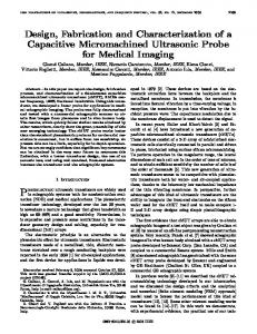
Fig. 3. Scanning electron micrograph (SEM) of 100-�m-high 2.6-mm-diameter rotary electrostatic actuator made via the HexSil process from a 3-�m-thick film of low-pressure chemical-vapor-deposited (LPCVD) polysilicon. Fig. 1. The servo positioning mechanism of a conventional magnetic disk drive.
Fig. 2. Exploded view of the microactuator assembly. The microactuator is sandwiched between the slider and a conventional gimbal.
at the read/write head. As shown in Fig. 3, the actuator consists of a fixed outer ring, or stator, and a mobile inner ring, or rotor, which is connected to an anchored central column via narrow polysilicon flexures. Actuation is accomplished via capacitive parallel plates, which are attached to the rotor and stator in opposing pairs. A voltage applied across these plates results in an electrostatic force which rotates the central rotor. The stator is made up of four separate electrically isolated quadrants. In Fig. 3, the isolation is achieved with thin breakaway beams connecting the stator quadrants. An electrostatic design was chosen for ease of fabrication—the structural material of the device need only be conductive, rather than ferromagnetic or piezoelectric. Furthermore, electrostatic actuators allow high accuracy, capacitive measurement of displacement, and are capable of high-bandwidth operation [10]. C. HexSil Fabrication Process The height-to-width aspect ratio of an electrostatic actuator is an extremely important design parameter for two reasons. First, for a fixed capacitive gap, the actuator torque output is linearly proportional to the structural height and therefore increases linearly with aspect ratio. Second, it is important that any uncontrollable cross-axis resonances be well above the servo bandwidth. For flexures with a rectangular cross section, the ratio of the cross-axis natural frequencies to the in-plane natural frequencies increases linearly with aspect ratio.
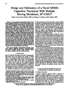
Fig. 4. A view of one quadrant of the rotary microactuator, showing the flexural suspension, electrostatic plates, and breakaway tethers. Note that the solder bumps are actually electroplated onto interconnect on a glass target die.
Until recently, methods for producing high-aspect-ratio structures relied on long etches in plasma chambers which accommodate only one wafer at a time. The HexSil process allows the fabrication of high-aspect-ratio-molded CVD polysilicon structures [11]. The unique feature of this process is that it relies on a reusable silicon mold, significantly lowering the price of finished parts. After fabrication, the finished structure is solder bonded to a target substrate, and the mold wafer is ready for the next fabrication cycle. II. ACTUATOR FABRICATION One quarter of the quad-symmetric microactuator layout is shown in Fig. 4. The structural material is in situ phosphorousdoped polysilicon, which is metalized with copper on the bonding surfaces to create solder-wettable pads. The solder bumps shown in Fig. 4 are plated on a target die and optically aligned to these pads during the transfer process [12]. Thin polysilicon tethers are used to anchor the structure to the mold wafer before bonding. Previous work has demonstrated a similar process for the transfer of static structures, such as vacuum encapsulated shells [13]. A. Fabrication Process Flow A simplified fabrication process flow is shown in Fig. 5. The first step is to use reactive ion etching (RIE) to etch deep trenches into a silicon mold wafer. The depth of the
HORSLEY et al.: DESIGN AND FABRICATION OF ANGULAR MICROACTUATOR
143
(a)
(b)
(c)
(d)
(e)
Fig. 6. SEM showing 100-�m-high flexures connecting the rotor to the anchored central column. The flexures have an aspect ratio of 30 : 1, which provides high-vertical and in-plane stiffness.
is removed by an etch in concentrated hydrofluoric acid (HF), which etches the PSG layer at approximately 20 m/min, but does not significantly attack the copper for etch times of up to 60 min. After the oxide etch, the structure is held in the mold by thin polysilicon tethers, which will break away when the structure is transferred to a target die [Fig. 5(c)]. The copper mounting pads on the actuator are optically aligned to solder bumps on the target [Fig. 5(d)], and the two dice are contacted together for solder reflow [Fig. 5(e)]. After the bond has cooled, the two dice are separated, breaking the thin tethers and leaving the released actuator bonded to the target substrate [Fig. 5(f)]. Residual polysilicon from the breakaway tethers may be removed from the mold wafer with a long HF etch or by mechanical polishing. III. FABRICATION RESULTS
(f)
Fig. 5. Simplified HexSil process flow. (a) The microactuator is fabricated as a thin film in the deep RIE-etched Si mold wafer. (b) The surface layer is patterned. (c) Following removal of the sacrificial layer, (d) and (e), the actuator is aligned and bonded to a target substrate. (f) Retraction of the mold wafer allows the fabrication process to begin again.
trenches determines the height of the fabricated structure. Next, a two-level sacrificial oxide layer is deposited. The first layer consists of 1 m of phosphosilicate glass (PSG), which is used to provide a fast-etching release layer. However, a second layer consisting of 3- m-thick conformal SiO is needed to coat the trench side walls. Anchor holes are patterned through the oxide, after which the structural layer of doped polysilicon is deposited by CVD [Fig. 5(a)]. This polysilicon makes contact with the silicon mold wafer at the anchor points. The surface polysilicon is then patterned, leaving pads for mounting the actuator. A plating-seed layer consisting of a 5-nm Cr adhesion layer beneath 100-nm Cu is evaporated onto the wafer surface. Next, copper bonding pads are electroplated using a 4–5- m-thick photoresist mask as a plating mold [Fig. 5(b)]. After electroplating, the photoresist is stripped in acetone, and the thin seed layer is removed from the unplated areas by ion milling. The sacrificial oxide
Two successful fabrication runs were made, the first using mold wafers which were etched to a depth of 100 m using a transformer-coupled plasma (TCP) etcher manufactured by surface technology systems (STS’s). The actuators fabricated in this first run were used to develop the solder-bump transfer process. Unfortunately, the mold wafers were accidentally destroyed before the process was fully developed, so these structures were not actuated. The second fabrication run used wafers which were only etched to a depth of 30 m due to equipment limitations. A 100- m-high structure from the first run, which was released and transferred onto an adhesive pad, is shown in Fig. 6. The 3- m-wide flexures connecting the rotor to the anchored central column were fabricated with a maximum aspect ratio of 30 : 1, while the 12.5- m capacitive gap had a maximum aspect ratio of 8 : 1. The aspect ratio of HexSil beams can be much greater than that of the gaps between them, since the beam spacing is determined by the separation of the mold trenches plus twice the thickness of the sacrificial oxide layer. In turn, the minimum separation between the mold trenches is determined by the aspect ratio of the RIE process used to create the mold. The maximum available RIE aspect ratio is currently 25 : 1, yielding a maximum capacitive gap aspect ratio of approximately 12 : 1. The beam thickness, on the other hand, may be as thin as 1–2 m, so aspect ratios of 100 : 1 are possible. Note that in both actuator designs, the rotor and stator elements are transferred from the mold
144
JOURNAL OF MICROELECTROMECHANICAL SYSTEMS, VOL. 7, NO. 2, JUNE 1998
Fig. 7. SEM of stator capacitor tip between two rotor capacitors.
(a)
(b)
Fig. 9. Flexure design. (a) SEM photograph of 30-�m-tall structure. (b) Flexure dimensions.
link of the flexure (180 m), polysilicon (170 Gpa), and about the axis
denotes the elastic modulus of is the area moment of inertia
(2)
Fig. 8. SEM of an actuator which has been solder bonded to a target die. Several broken tethers are visible around the central hub.
where is the height of the structure (variable) and is the width of the flexure (3 m). For comparison, the vertical (out-of-plane) stiffness of each flexure is given by (3)
wafer as separate pieces to allow electrical isolation. The disadvantage of this approach is that a slight misalignment of the rotor and stator causes a mismatch in the electrostatic force, resulting in an asymmetric actuation characteristic. A close-up of the capacitive gap between the parallel plates of the stator and rotor after bonding is shown in Fig. 7. The leftmost two beams (indicated with arrows on the photo) are the rotor/stator plate pair, while the beams on the right make up the rotor plate of the neighboring capacitor pair (not shown). Alignment accuracy between transferred parts is better than 0.5 m. Additionally, the photo shows that the intersection of the 3- m polysilicon HexSil beams is curved, leading to minimal stress concentrations. Fig. 8 shows a 30- m-high actuator, which has been solder bonded to a target die. The rotor and capacitive plates are suspended approximately 8 m above the target substrate, leaving them free to rotate. Also visible are the mold tethers which were broken after solder bonding the structure to the target.
where
denotes the area moment of inertia about the
(4) and
and
are dimensionless constants (5)
Substituting the measured actuator dimensions into (1), the total rotational stiffness of a 30- m-high structure with eight flexures is N
m/rad
The design of the eight flexures supporting the actuator rotor is shown in Fig. 9. Neglecting bending of the short links, the in-plane rotational stiffness of each flexure is given by (1) where denotes the radius from the center of rotation to the denotes the length of main end of the flexure (530 m),
(6)
The rotational stiffness from (6) is 58% lower than the designed value because the fabricated beam width of 3 m differed significantly from the designed beam width of 4 m. The total vertical stiffness calculated from (3) is mN
IV. FLEXURE DESIGN
axis
m
(7)
The vertical stiffness from (3) is an important parameter because the picoslider is typically subjected to a 20-mN preload under normal operating conditions. Referring to the value in (7), the actuator rotor is expected to deflect by approximately 1.5 m under this preload. While such a deflection is tolerable, note that because the vertical stiffness increases with the cube of the actuator height , the deflection of a 100- m-high structure would be less than 50 nm.
HORSLEY et al.: DESIGN AND FABRICATION OF ANGULAR MICROACTUATOR
145
and
V. ACTUATION DYNAMICS
is an electrostatic spring term
The actuator rotor is coupled to the fixed stator via mechanical flexures, and the dynamics of the device can be expressed as a second-order system (8) is the rotor moment of inertia, is the damping, where is the mechanical spring stiffness of the flexures, and is the electrostatic torque. A. Electrostatic Torque capacitive plate Electrostatic torque is produced by pairs, half of which rotate the actuator clockwise, the other half counterclockwise. For small rotation angles , these plates may be modeled as parallel plate capacitors separated by gaps and
(15) B. Linearized Model Substitution of (13) into (8) yields a linear dynamic model (16) , implying that The linearized system is stable for the nonlinear system given by (8) is stable for small rotations. Note that the effect of the electrostatic spring term is to destabilize the system, reflecting the tendency of the capacitive plates to pull in for sufficiently high voltage. The maximum bias voltage for which the actuator remains stable is found by setting the electrical spring stiffness in (15) equal to the mechanical spring stiffness and solving for
(9) where is defined to be the distance from the centroid of the is the nominal plate to the center of rotation of the rotor and capacitive gap with zero rotation. Applying a voltage to one half the structure and to the other half creates a net torque (10) is the area of each plate and where of air. Substituting the values for and (10) yields
will result in instability with Note that values of zero rotation. When the actuator is operated in nondifferential , the capacitors will pull together at a rotation mode with . The voltage required to achieve this of approximately rotation is referred to as the pull-in voltage
is the permittivity given in (9) into
(11) In reality, each capacitive plate on the rotor has two neighboring stator plates which are biased at the same potential, as shown in Fig. 4. The effect of the second stator plate is to reduce the total output torque, but because the gap between this plate and the rotor plate increases radially and is much greater than the gap between the primary rotor/stator plate pair, this parasitic torque will be neglected. A common method for linearizing the quadratic voltage nonlinearity of the electrostatic force is to use a differential and a variable driving scheme with a fixed bias voltage control voltage [6] (12) The result of the differential drive approach is to eliminate so even terms from the series expansion for that only odd powers remain. Assuming small rotations about , the electrostatic torque may then be approximated by (13) where
(17)
represents the gain from voltage to torque (14)
(18) Comparing (17) with (18) reveals that for zero displacement the device will remain stable at a 30% higher bias voltage when it is operated with a differential drive, although the differential mode operation is still limited to approximately the same range of rotations as the nondifferential mode. C. DC Gain Experimental measurements of the static rotation characteristic of the actuator were performed by applying differential VDC and 38 V 38 V drive voltages with to the two halves of the stator. These results are plotted in Fig. 10. Note that a slight misalignment of the rotor has occurred in the transfer process, resulting in an asymmetric response. The maximum observed rotation was 2.9 mrad at 73 V, but the theoretical maximum rotation predicted by (18) is 4.6 mrad at 80 V. Because the read/write elements of the slider will be 600 m from the center of rotation of the actuator, a 2.9-mrad rotation corresponds to a linear translation of 1.74 m. The experimental data was fit with a theoretical model corresponding to the steady-state solution to (8) (19) and the capacitive Because both the flexural stiffness depend on the polysilicon beam width, the fit was gap generated by adjusting this width in the model until the curve calculated from (19) matched the experimental data points. It
146
JOURNAL OF MICROELECTROMECHANICAL SYSTEMS, VOL. 7, NO. 2, JUNE 1998
Fig. 10. Actuator rotation versus applied voltage. The solid line represents the response predicted by the full nonlinear model, while each experimental data point is indicated by an x. Note that the data points for positive voltages are slightly below the theoretical curve due to a mismatch in the electrostatic force from the two halves of the actuator. TABLE I LINEAR MODEL COEFFICIENTS
AT
vb = 40 VDC
TABLE II ROTOR MOMENT OF INERTIA
is the polysilicon beam width that deviated most significantly between design and fabrication. The geometric values used to produce the theoretical fit were then used to compute values and , which are summarized in Table I. for D. Resonant Frequency The resonant frequency of the linearized system described in (16) is given by (20) where the dependency of the electrostatic spring term on the bias voltage has been made explicit. The result of this effect is that the resonant frequency of the device may be tuned over a 10% range by varying the bias voltage. Fig. 11 shows a plot of the resonant frequency of two different actuator designs for varying bias voltages. In this experiment, the push–pull segments of the stator were biased at 38 V and ground, respectively, while the rotor bias was varied. Due to the asymmetric bias conditions, the expression used to model was (21) where and
Fig. 11. Actuator resonant frequencies for varying bias voltages. The plot on the left is for the first actuator design, which had a lower moment of inertia than the second design, shown on the right. In each plot, the measured resonant frequency is indicated by an x, while the solid line indicates a second-order least-squares fit to the data, and the dashed line indicates the resonant frequencies predicted using the theoretical model.
V is the bias on one rotor segment V is the bias on the second rotor segment.
Note that this model assumes that the rotor rotation due to the applied bias is negligible. A second-order least-squares fit was performed on the data, allowing an estimate of the rotational to be produced. Using known geometrical values stiffness and , the moment of inertia was then to compute adjusted to produce a plot which matched the measured response. The measured values are summarized in Table II along with the value predicted from the actuator layout. For comparison, note that the moment of inertia of a typical picoslider is approximately 330 pgm , an order of magnitude greater than the rotor moment of inertia. E. Actuator Frequency Response In order to allow the actuator to be controlled, the resonant frequency must be either well below or well above the intended closed-loop control bandwidth. To achieve a tracking accuracy of less than 100 nm, it is predicted that a bandwidth of 2 kHz will be required [6]. Thus, the resonant frequency must be either below 2 kHz, or above approximately 10 kHz. However, increasing the resonant frequency reduces the dc gain. Choosing a resonant frequency below 2 kHz maximizes the dc gain and allows the actuators to provide a 1- m range over the entire servo bandwidth. Using the measured parameters discussed in the previous section, the actuator frequency response was simulated and is shown for the first actuator design, both with and without a picoslider payload, in Fig. 12. A minimum dc gain of 50 rad/V is required to achieve the desired range of 2 mrad
HORSLEY et al.: DESIGN AND FABRICATION OF ANGULAR MICROACTUATOR
147
ACKNOWLEDGMENT The authors thank C. Keller for assistance with the HexSil process, R. Wilson for the SEM micrographs, Surface Technology Systems for deep RIE of several mold wafers, and J. Bustillo and the staff of the Berkeley Microfabrication Laboratory for their continued help. REFERENCES
Fig. 12. Simulated actuator frequency response. The circled open-loop crossover is the frequency at which the gain drops below 50 �rad/V. TABLE III LINEARIZED ACTUATOR MODEL AT vb = 40 VDC
at a drive voltage of 40 V, and the maximum frequency at which this gain is achieved with the slider payload is defined as the open-loop crossover. This frequency, which is circled on the plot in Fig. 12, in turn determines the maximum closed-loop bandwidth. The dc gain, resonant frequency, and predicted closed-loop bandwidth are summarized in Table III. Note that the resonant frequency listed in the table differs slightly from the measured resonant frequencies shown in Fig. 11 due to the symmetric bias condition. VI. CONCLUSION An angular microactuator was designed and fabricated using the HexSil process. The actuators have been shown to have a maximum range of 2.9 mrad, corresponding to a linear translation of 1.74 m at the read/write transducers of a 30% slider. A theoretical model for the actuator dynamics has been created using parameters extracted from the dc rotation tests and resonant frequency measurements. The actuator frequency response predicted by this model will guarantee an operating range of 1 m up to a maximum frequency of 2.5 kHz. Additionally, the devices were batch fabricated with a lowcost process using a 3- m LPCVD deposition of polysilicon to create structures, which are up to 100 m thick. The finished structures were transferred from the reusable mold wafer to a target die using a solder bond. This process will allow the integration of micromechanical structures with standard CMOS at low cost and minimal additional processing complexity.
[1] E. Grochowski and R. F. Hoyt, “Future trends in hard disk drives,” IEEE Trans. Magn., vol. 32, no. 6, pt. 1, pp. 1850–1854, 1996. [2] K. Takaishi et al., “Microactuator control for disk drive,” IEEE Trans. Magn., vol. 32, no. 3, pt. 2, pp. 1863–1866, 1996. [3] S. Koganezawa, K. Takaishi, Y. Mizoshita, Y. Uematsu, and T. Yamada, “Development of an integrated piggyback milli-actuator for high density magnetic recording,” in Int. Conf. Micromechatronics for Information and Precision Equipment, Tokyo, Japan, July 1997. [4] S. Nakamura, K. Suzuki, M. Ataka, and H. Fujita, “An electrostatic micro actuator for a magnetic head tracking system of hard disk drives,” in 9th Int. Conf. Solid-State Sensors and Actuators (Transducers’97), Chicago, IL, June 1997, pp. 1081–1084. [5] T. Imamura, T. Koshikawa, and M. Katayama, “Transverse mode electrostatic microactuator for MEMS-Based HDD Slider,” in IEEE Proc. 9th Int. Workshop on Micro Electro Mechanical Syst., San Diego, CA, Feb. 1996, pp. 216–221. [6] L.-S. Fan, H. H. Ottesen, T. C. Reiley, and R. W. Wood, “Magnetic recording-head positioning at very high track densities using a microactuator-based, two-stage servo system,” IEEE Trans. Ind. Electron., vol. 42, no. 3, pp. 222–233, 1995. [7] W. Tang, V. Temesvary, R. Miller, A. Desai, Y. C. Tai, and D. K. Miu, “Silicon micromachined electromagnetic microactuators for rigid disk drives,” IEEE Trans. Magn., vol. 31, no. 6, pp. 2964–2966, 1995. [8] W. N. Sharpe, Jr., B. Yuan, and R. Vaidyanathan, “Measurements of Young’s modulus, Poisson’s ratio, and tensile strength of polysilicon,” in IEEE Proc. 10th Int. Workshop on Micro Electro Mechanical Syst., Nagoya, Japan, Feb. 1997, pp. 424–429. [9] S. K. Aggarwal, D. A. Horsley, R. Horowitz, and A. Pisano, “Microactuators for high density disk drives,” in Proc. Am. Control Conf., Albuquerque, NM, June, 1997, pp. 3979–3084. [10] P. Cheung, R. Horowitz, and R. T. Howe, “Design, fabrication, position sensing, and control of an electrostatically-driven polysilicon microactuator,” IEEE Trans. Magn., vol. 32, no. 1, pp. 122–128, 1996. [11] C. G. Keller and M. Ferrari, “Milli-scale polysilicon structures,” in IEEE Solid-State Sensor and Actuator Workshop, Hilton Head, SC, June 1994, pp. 132–137. [12] A. Singh, D. A. Horsley, M. B. Cohn, A. P. Pisano, and R. T. Howe, “Batch transfer of microstructures using flip-chip solder bump bonding,” in 9th Int. Conf. Solid-State Sensors and Actuators (Transducers’97), June 1997, pp. 265–268. [13] M. B. Cohn, Y. Liang, R. T. Howe, and A. P. Pisano, “Wafer-towafer transfer of microstructures for vacuum packaging,” in 1996 IEEE Solid-State Sensor and Actuator Workshop, Hilton Head, SC, June, pp. 32–35.
David A. Horsley received the B.S. and M.S. degrees in mechanical engineering at the University of California, Berkeley, in 1992 and 1994, respectively. He is currently working towards the Ph.D. degree in mechanical engineering at the University of California, Berkeley. In 1995, he joined the Berkeley Sensor and Actuator Center as part of a project to develop MEMS components for magnetic disk drives. His research interests include the design of MEMS devices for data storage and optical applications as well as servo control issues in MEMS.
148
JOURNAL OF MICROELECTROMECHANICAL SYSTEMS, VOL. 7, NO. 2, JUNE 1998
Michael B. Cohn received the Ph.D. degree from the University of California, Berkeley, in 1997. His interests include wafer–wafer transfer of microstructures by bump bonding and vibratory self-assembly of microstructures using electrostatic traps.
Angad Singh received the B.S. degree in electrical engineering from Visvesvaraya Regional College of Engineering, Nagpur, India, in 1994 and the M.S. degree in electrical engineering from Case Western Reserve University, Cleveland, OH, in 1996. He is currently a Researcher at the Berkeley Sensor and Actuator Center, University of California, Berkeley. As part of a fast-moving technology development research group whose charter is to capitalize on the advantages of MEMS as applied to disk drives, he is involved in developing novel fabrication technologies for next-generation high-aspect-ratio MEMS devices. In addition, he is actively pursuing research in the area of MEMS assembly and packaging.
Roberto Horowitz received the B.S. degree with highest honors in mechanical engineering in 1978 and the Ph.D. degree in 1983, both from the University of California, Berkeley. In 1982, he joined the Department of Mechanical Engineering, University of California, Berkeley, where he is currently a Professor teaching and conducting research in the areas of adaptive, learning, nonlinear and optimal control and mechatronics, with applications to disk file systems, robotics, microelectromechatronic systems (MEMS’s) and intelligent vehicle and highway systems (IVHS’s). Dr. Horowitz was the recipient of a 1984 IBM Young Faculty Development Award and a 1987 National Science Foundation Presidential Young Investigator Award.
Albert P. Pisano received the all B.S., M.S., M.Phil., and Ph.D. engineering degrees from Columbia University, NY, in 1976, 1978, 1978, and 1981, respectively. He was a Member of the Research Staff at Xerox Corporation from 1981 to 1983 before joining the faculty of the Department of Mechanical Engineering, University of California, Berkeley, in 1983. He is currently the MEMS Program Manager at the Defense Advance Research Project Agency’s Electronic Technology Office and on administrative leave from the University of California, Berkeley, where he serves as a Codirector of the Berkeley Sensor and Actuator Center, an NSF/Industry/University Research Cooperative. He conducts research in the area of design, optimization, and fabrication of microactuators, microbiological devices microinertial instruments, and microtest devices (for friction and impact measurements), all in the size range from 100 to 1000 �m.