3600504
IEEE TRANSACTIONS ON APPLIED SUPERCONDUCTIVITY, VOL. 22, NO. 3, JUNE 2012
Design, Fabrication, and Operating Test of the Prototype HTS Electromagnet for EMS-Based Maglev Chang Young Lee, Jung Min Jo, Young Jae Han, Yoon Do Chung, Yong Soo Yoon, Sukjin Choi, Young Jin Hwang, Hyun Chul Jo, Jae Young Jang, and Tae Kuk Ko, Member, IEEE
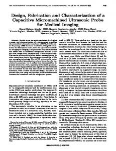
Abstract—The prototype highsuperconducting electromagnet (HTS-EM) for high-speed EMS Maglev was successfully demonstrated in EMS system up to the vehicle running speed of 500 km/h. The EM was designed to interface with the existing propulsion system used in the German high-speed Maglev. The rating levitation force of the EM was designed to correspond to the weight of the EM at a 20 mm levitation gap. Electromagnetic forces were simulated and compared with the test results in order to verify the design feasibility of the HTS-EM. Operating tests revealed that the HTS-EM was fully operational in zero-power control mode. However, the operating current of the HTS coil was affected by the control current when the guideway disturbance occurred. The design feasibility and operability of the HTS-EM was verified in the study. Index Terms—Electromagnet, EMS, levitation, Maglev. Fig. 1. Configuration of an EMS system using a prototype HTS-EM.
I. INTRODUCTION
T
HE WORLDWIDE use of Maglev technology is proof that it is a reliable and affordable mean of rail transportation. However, many believe that Maglev is more expensive than conventional wheel-on-rail technology. Since the low-speed urban Maglev project was successfully launched in Korea in 2006, the country has been exploring cost-effective technologies for use on a high-speed Maglev project that uses electromagnetic suspension (EMS) technology. The authors of this paper have studied one of the candidate technologies; an EMS system with a large airgap, that uses a superconducting electromagnet as the vehicle magnet. The system’s increased airgap allows it to effectively handle irregularities in guideway alignment. This feature will lead to a significant decrease in construction costs. The Northrop Grumman Co. proved the feasibility of the design in 1995, when they had a successful demonstration using a small-scale electromagnet using wire [1], [2]. On the basis of Grumman’s
Manuscript received August 31, 2011; accepted January 24, 2012. Date of publication March 22, 2012; date of current version May 24, 2012. C. Y. Lee, J. M. Jo, and Y. J. Han are with Korea Railroad Research Institute, Woram Dong, Uiwang Si 437-757, Korea (e-mail:
[email protected]). Y. D. Chung is with the Department of Electrical Engineering, Suwon Science College, Hwasung Si 445-742, Korea. Y. S. Yoon is with the Department of Electrical Engineering, Shin Ansan University, 671 Choji-Dong, Danwon-Gu, Ansan 425-792, Korea. S. Choi, Y. J. Hwang, H. C. Jo, J. Y. Jang, and T. K. Ko are with the Department of Electrical and Electronic Engineering, Yonsei University 134 Sinchon-dong, Seoul 120-749, Korea. Color versions of one or more of the figures in this paper are available online at http://ieeexplore.ieee.org. Digital Object Identifier 10.1109/TASC.2012.2186778
achievements, we fabricated a prototype electromagnet desuperconducting coil (HTS-EM), and signed with a highsuccessfully demonstrated it at the vehicle running speed of 500 km/h. Our study focuses on the operability of the HTS-EM as a preliminary research in designing a full-scale EMS system. This paper describes the design, fabrication and operating test results of the HTS-EM. II. DESIGN AND FABRICATION A. Configuration of an EMS System using a Prototype HTS-EM Fig. 1 shows the schematic diagram of an EMS system that uses a prototype HTS-EM. The guideway has slots in which the LSM winding cables are embedded. The levitation principle is the same as that of a conventional EMS system using a normalconducting electromagnet (NC-EM), but there are a few differences in system configuration. The HTS-EM consists of a control coil and an HTS coil wrapped around a horseshoe-shaped iron core. The HTS coil, which operates in DC mode, produces magneto-motive force (mmf) required to suspend the EM at a large air-gap. The control coil is used only for suspension control. If the EM is stably levitated at a rating airgap, the EM is operated in zero-power control mode. The control system consists of an analog and a digital controller. The digital controller is designed to compute the reference current using the airgap and acceleration information from EM. The computed reference current serves as a command
1051-8223/$31.00 © 2012 IEEE
LEE et al.: DESIGN, FABRICATION, TEST OF PROTOTYPE HTS ELECTROMAGNET FOR EMS-BASED MAGLEV
3600504
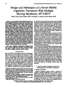
Fig. 3. 2-D Magnetic field distribution of an HTS-EM. Fig. 2. Design features of the prototype HTS-EM.
signal to the analog controller. The analogue controller generates a pulse-width modulation (PWM) signal to control the current of NC coil. This is done by comparing the reference current to that of the control coil. Since the HTS-EM is initially excited by the HTS coil, the EM requires the additional opposite magnetic force to release the attraction force when the EM is close to the guideway. Therefore, the four-quadrant chopper unit is used to drive the control coil with bidirectional current. B. Prototype HTS-EM Fig. 2 shows the design features of the prototype HTS-EM. The dimensions were set so that the prototype is compatible with the German high-speed Maglev’s propulsion system. In order to ensure the compatibility, the magnetic pole pitch of the HTS-EM was designed to match the three-phase armature winding pitch of the guideway. This is also the same as the pole pitch of the normal conducting EM used in the existing system [3], [4]. The demonstration gap of the prototype was set at 20 mm. the Iron core and the guideway were fabricated with 0.8 mm-thick laminated silicon steel. In order to design the HTS coil and the control coil, levitation forces as the mmf increases were preliminary simulated with the electromagnetic equation expressed as follows [5], [6]: (1) where, B is the average magnetic flux density at the gap between the guideway and EM, and S is the area per pole. B was calculated by 2-D FEM analysis as shown in Fig. 3. The simulated curves are shown together with the measured curves in Fig. 8. The minimum mmf required to levitate the EM was determined from the levitation force corresponding to the weight of the EM at a 20 mm levitation gap. In the simulated curves of Fig. 8, the mmf value required for a 20 mm gap was estimated to be about 12 kAt when the EM weight was considered to be a maximum of 13 kN. We set this mmf value as the minimum design criteria for the HTS coil. C. HTS Magnet Fig. 4 shows the design feature of an HTS magnet. The HTS coil was cooled by in the cryostat. The maximum design size of the coil was limited by the size of the cryostat. The HTS
Fig. 4. Design results of the HTS magnet.
TABLE I SPECIFICATIONS OF BI-2223 TAPE
coil was formed with four-double pancake stacked coaxially on FRP bobbins with a diameter of 130 mm. The total number of turns was set at 360 with 90 turns for each double pancake. The cryostat was made of SUS 304 which is non-ferromagnetic metal. Some degree of eddy-current loss induced by variations in the control current was expected on the cryostat, but we ignored it when making the prototype HTS-EM. Recently developed YBCO tapes would be the best HTS material in regards to cost and performance, but special attention is required to fabricate a coil. Since we wanted focus on the design and operability of the HTS-EM in this study, we opted to use Bi-2223 tape, so as to avoid any fabrication risks. Table I shows the specifications of the Bi-2223 tape used. From the 2-D magnetic field analysis for the design, the critical current, , was estimated to be at least 42 A at the cooling temperature of 77 K. We referenced the curves of the Bi-2223 tape presented by the manufacture. Thus, the consequent mmf that the HTS coil could produce was estimated to be 15 kAt. Fig. 5 shows the operating current and
3600504
IEEE TRANSACTIONS ON APPLIED SUPERCONDUCTIVITY, VOL. 22, NO. 3, JUNE 2012
Fig. 5. Initial current operating test for the HTS coil.
Fig. 7. EMS system test setup.
was 24 A. The control coil was designed to have a total of 300 turns. Consequently, the mmf that could be generated by the control coil was calculated at 7.2 kAt. Fig. 6 shows the fabricated HTS-EM. The design results of the prototype HTS-EM are summarized in Table II III. OPERATING TEST A. Test Setup
Fig. 6. View of the fabricated HTS-EM. TABLE II DESIGN SUMMARY OF PROTOTYPE HTS-EM
In commercial EMS Maglev, an elevated guideway, which consists of girders with a specific span length and piers to support the girders, is commonly used. While the vehicle is running on the guideway, the girders between piers bend slightly due to the weight of the vehicle. This bending causes fluctuations in the levitation gap between the vehicle and the guideway. This is the most dominent disturbance of the EMS Maglev. The disturbance frequency, f, is related to the vehicle speed as follows. (2)
the voltage measured on the fabricated HTS coil to monitor a quench during the initial operating test. The initial current operating test for the HTS coil was successful at 42 A for 1 min. The performance of the HTS coil was verified to ensure the design criteria of the mmf. D. Control Coil A copper conductor with a cross section of 6 was used for the control coil. The maximum continuous current density of the copper conductor was assumed to be 4 . The consequent maximum continuous rating current of the control coil
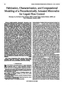
where, v and L are the vehicle speed and the span length, respectively. In this study, we assumed a span length as 25 m which is the standard span length of the German high-speed Maglev [7]. The EMS system was tested on a letivation tester, which is able to simulates guidway distrubance, as shown in Fig. 7. The disturbance is controlled by the actuator located at the center of the tester, and the levitation force of the HTS-EM is monitored by a load cell between the actuator and the guideway. A linear motion guide ensures that the EM can only move in a vertical direction. B. Levitation Force-mmf Characteristics Levitation forces were measured in order to prove the feasibility of the electromagnetic force design of the HTS-EM. As shown in the levitation force-mmf curves of Fig. 8, the measured levitation forces-mmf curves are in good accord with the simulated results, but the measured forces are about 10%–20% higher than the simulations. A simulation that uses 2-D FEM analysis of the design model appears to be reasonable, but it needs to improve the accuracy.
LEE et al.: DESIGN, FABRICATION, TEST OF PROTOTYPE HTS ELECTROMAGNET FOR EMS-BASED MAGLEV
3600504
Fig. 10. Operating current by dynamic levitation test at 5.5 Hz. Fig. 8. Levitation force-mmf curves of prototype HTS-EM.
airgap of 20 mm because the airgap fluctuations exceeded the range of the gap sensor. We took this limitation into account, and we successfully tested the system at an airgap of 17 mm. Fig. 10 shows the operating currents monitored during the test with a disturbance frequency of 5.5 Hz. In the dynamic levitation test, the control current fluctuated as the disturbance. Some fluctuation in the operating current of the HTS coil was observed as the control current changed. This test revealed that the operating current of the HTS coil could be affected by the control current because of the magnetic interface between both coils. Such fluctuation not only causes AC loss, but it also causes the rating current margin of the HTS coil to decrease. In order to minimize this problem, controlled DC current source will be used to operated the HTS coil in the full-scale system. Fig. 9. Operating sequence of steady-state levitation test.
C. Steady-State Levitation Test Steady-state levitation was successfully demonstrated. Fig. 9 shows the current operating sequence for each coil and the levitation force and airgap of EM monitored during the operation. The test was carried out at an 20 mm airgap. The initial position of the EM was set at a distance of 23 mm from the guideway, which is the maximum that can be detected by the gap sensor we used. The initial excitation current for the HTS coil was set at 27.7 A, which was determined from the levitation force-mmf curve in Fig. 8. After finishing the excitation, the controller was activated in order to generate the remaining mmf required for levitation. As shown in Fig. 9, the control current maintained almost 0 A when it reached steady-state levitation. This test proved that the HTS-EM could be fully operational in zero-power control mode. D. Dynamic Levitation Test The dynamic levitaton tests focused on the operability of the EM under the vehicle’s running conditions. The tests were carried out up to the disturbance frequency of 5.5 Hz, which corresponds to the vehicle’s running speeds of 500 km/h in (2). The disturbance displacement of the guideway was set up to a maximum of 2.5 mm. The test could not be performed at an
IV. CONCLUSION The prototype HTS-EM was successfully demonstrated at the vehicle running speed of 500 km/h. It was confirmed that The HTS-EM is fully operational in zero-power control mode when the EM is stably levitated. Some fluctuation in the HTS coil operating current was observed when guideway disturbance occurred. This problem will be improved by a controlled DC current source. Operating test results will be reflected in the design of the full-scale system. REFERENCES [1] S. Kalsi, M. Proise, T. Schultheiss, and B. Dawkins, “Iron-core superconducting magnet design and test results for maglev application,” IEEE Trans. Appl. Supercond., vol. 5, no. 2, pp. 964–967, Jun. 1995. [2] S. Kalsi, Applications of High Temperature Superconductors to Electric Power Equipment, Wiley-IEEE Press, 2011, ch. 10. [3] J. H. Lever, Technical Assessment of Maglev System Concepts Cold Regions Research & Engineering Lab., US Army Corps of Engineers, Special Report 98-12, Oct. 1998. [4] G. Bohn and G. Steinmetz, “The electromagnet levitation and guidance technology of the transrapid test facility Emsland,” IEEE Trans. Magn., vol. Mag-20, no. 5, pp. 1666–1671, Sep. 1984. [5] P. K. Sinha, Electromagnetic Suspension-Dynamics & Control. London: Peter Peregrinus Ltd., 1987, ch. 4. [6] R. Goodall, “Generalized design models for EMS maglev,” in Proc. 20th Conf. Magnetically Levitated Systems and Linear Drives, San Diego, 2008, no. 007. [7] E. Grossert, “Actual development in guideway constructions at the example of the Transrapid Munich project,” in Proc. 19th Conf. Magnetically Levitated Systems and Linear Drives, Dresden, 2006, no. 131.