Proceedings of the IEEE International Conference on Mechatronics & Automation Niagara Falls, Canada • July 2005
Design and Implementation of a Collaborative Virtual Haptic Surgical Training System Brahim Chebbi, Daniel Lazaroff and Francis Bogsany School of Advanced Technology Algonquin College Ottawa, Ontario CANADA
[email protected]
Peter X. Liu
Liya Ni and Mauro Rossi
Department of Systems &Computer Engineering Carleton University Ottawa, Ontario CANADA
[email protected]
Handshake VR
sight, or haptics and graphics, and is therefore a hapto-visual environment. This paper describes the logical and physical design of the system. Section II discusses the overall system architecture. Section III and IV describe the haptic control unit and the graphical unit respectively. Section V discusses collaboration between the two, geographically separated stations of the system. Section VI describes the implementation and the physical configuration. The current use of the system is described in section VII and the conclusion includes some planned future research and applications of the system.
Abstract – The high level design of a hapto-visual telementoring virtual environment consisting of two networked stations allowing two users to collaborate within the learning environment is outlined. The physical implementation and the operation of the system are described. This system is designed to be used for remote surgical training. It would allow surgeons to remotely train students in a networked hapto-visual virtual environment to perform simple tasks. Moreover, the system provides a platform for studying many aspects of Collaborative Virtual Environment (CVE) systems and their applications. Index Terms –Haptics, Virtual Reality (VR), Collaborative Virtual Environment (CVE), Tele-mentoring, Surgical training.II.
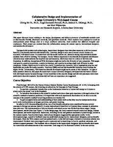
II. DESIGN OF SYSTEM Each station of the CVHSTS is logically divided into realtime haptic and non-real-time graphic components. The graphic component provides a 3D collaborative virtual environment with stereoscopic rendering. It is responsible for physical simulation. The haptic component provides a simplified real-time haptic collision detection and response. It also provides the tele-haptic functionality. The diagram in Fig. 1 shows the overall conceptual system design for one station. This design uses a server-client configuration similar to the model used in [10] and augments it with collaboration. The server, shown in the upper block, is the real time haptic component and the client, shown in the lower block, is the non real time graphic environment. Diamonds denote physical interfaces. VDU is the visual display unit and F6S is the MPB Freedom-6S haptic device. IP indicates communication over the Internet Protocol, including interfaces between the graphic and haptic components, and between two complete stations. The latter are labeled on the figure. The server and client communicate through TCP/UDP packets. The haptic component interfaces to and controls the MPB Freedom-6S haptic device. The real time haptic server is separated into two components implemented on separate computational platforms. The first component is used for local haptic control and the second one is used for tele-haptic control. All communication to the graphical component is mediated by the local haptic control component. The tele-haptic control component is proprietary to HandshakeVR, it contains the physical interface to the haptic device and is responsible for network time delay compensation.
I. INTRODUCTION Virtual reality (VR) is generally defined as a three dimensional computer generated environment which allows the user to interact with it and change it in real time. It has been used for many applications including: surgery simulation, rehabilitation, gaming applications, industrial simulations and e-commerce [1][2][3][4][5]. Haptics, which comes from the Greek verb “haptesthai” meaning “to touch”, adds to VR environments the ability that the user touches and feels the virtual objects present in the environment, enhancing the level of realism and presence [6]. A Collaborative Virtual Environment (CVE) allows users located in geographically different places to communicate and interact with each others in a shared environment through a distributed network such as a local area network (LAN) or the internet. Research is being conducted by many research groups on different aspects of CVE, such as network communications issues [7], system level distributed interaction issues [8] and user level distributed interaction issues [9]. The current research produced a CVE system, composed of two hapto-visual stations connected through the internet. The system named CVHSTS (Collaborative Virtual Haptic Surgical Training System) is intended to provide a collaborative virtual environment for training in medical procedures. The CVHSTS utilizes a mentoring metaphor, whereby a teacher interactively guides a student, and extends this via the internet to permit remote collaboration between the teacher and student, or tele-mentoring. It permits interaction and mentoring through the senses of touch and
0-7803-9044-X/05/$20.00 © 2005 IEEE
419 Phillip St Waterloo, Ontario CANADA lni,
[email protected]
315
To the haptic component it provides forces from the physical simulation and the virtual object parameters through TCP packets. The local haptic control unit communicates with the tele-haptic control unit by exchanging UDP messages containing local and remote haptic device data. In practice handling of incoming messages is done through a separate process then handling of outgoing messages for communication with both the graphical unit and the telehaptic unit. The control loop is responsible for collision detection and collision response. Collision detection consists of identifying contact between the tool used and the objects in the virtual environment. Collision response deals with computing the forces due to collision to be communicated to the operator by the haptic device.
Fig. 1 Functional diagram of one station of the CVHSTS
The graphics component, described in more detail in section IV, provides a hapto-visual virtual surgical environment. It also permits audio and video collaboration between the users of the two stations. III.
HAPTIC CONTROL
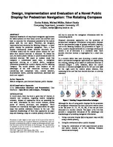
Fig. 2 Haptic control processes
Collision detection is performed at the graphics station and at the local haptic control loop. If no collision is reported at the graphics station, the local haptic control loop is notified and zero torque for each joint the haptic device is generated. The user feels no resistance forces from the haptic device. If collision is reported at the graphics station, the local haptic control station is notified and a second check is performed at the haptic control station. Since the local haptic control loop runs on a real time system it is more reliable then the graphics station and only if collision is still detected at this stage will the collisions forces to be communicated to the user be evaluated. This tandem collision detection is more efficient and gives better collision response then collision detection evaluated on one computing platform only. An algorithm calculating the distance between the end tip of the tool, and the plane of the closest element of the virtual object is used for collision detection. Collision response calculates the response forces as the sum of the a tissue force generated by the physical simulation at the graphics station, a spring force calculated at the haptic control station which depends on the distance between the end of the tool tip and the tangent plane
As mentioned previously, the haptic control is implemented on two components: a local haptic control component and a tele-haptic control component. In general terms, the local haptic control component is responsible for haptic rendering and the tele-haptic control component is responsible for network connection and time delay compensation. The discussion in the present paper focuses mainly on the local haptic control component. The haptic rendering system is middleware that connects the graphical environment to the haptic environment. To maintain control stability and consistency of the operator's haptic experience, the control loop must be evaluated at a stable update rate, necessitating the use of a real-time operating system for executing the control loop. Windows CE was chosen for this purpose. It is carefully partitioned into independent processes, to isolate errors and to protect components from faults. The main modules are shown in Fig. 2. The communication between the graphical unit and the haptic control unit is bi-directional. It provides the graphical unit with UDP messages containing the tool position and orientation data from both the local and remote haptic devices.
316
to the tissue and the friction force between the tool and the tissue. The same model has been used in [10].
The collaboration mechanism is required to maintain consistency between the participant's virtual models and to allow communication between them. It will be discussed in more detail in section V. The graphical rendering displays the virtual model. It uses the OpenGL API for commanding the graphical display hardware. The collision detection, the graphics rendering and the physical simulation are the main modules of the graphical component. They are implemented as separate threads accessing the common data through a mutex for synchronization and are explained in more detail below. The shared data is the virtual environment and the objects within it. In general it may consist of static rigid and dynamic rigid objects, as well as static or dynamic deforming objects. The present virtual environment consists of a static rigid workbench and tool-tray, a set of dynamic rigid tools and a static deforming rat. Both static and dynamic rigid objects are implemented as textured triangle meshes with reflections. Tools are specializations of dynamic rigid objects and additionally incorporate a simplified line-based collision representation. Static deformable objects extend the textured triangle mesh with a finite-element model that is evaluated by the physical simulation module.
The tele-haptic control component was implemented on a separate computing platform running Windows CE. It uses the TiDeCTM from HandshakeVR for network time delay compensation, and is referred to as TiDeCTM box. IV. GRAPHICAL UNIT The graphical component provides a virtual model of a surgical environment It has the following responsibilities: x User interface; x
System configuration;
x
Physical simulation;
x
Collaboration;
x
Graphical rendering.
The main modules of the graphical unit are shown in Fig. 3. It consists of a communications interface to the haptic component, a physical simulation module, a graphical rendering module, a shared data model, a collaboration module, data file loading functionality, and a user interface & configuration module.
A. Physical simulation To simulate physical deformation plate elements are assumed for the rat skin. The three dimensional loading on these elements is assumed to be a combination of in-plane loading and bending loading [11]. The stiffness matrices of all elements has been calculated and validated. At the time of writing of this paper the solution of the dynamic mass-springdamping equation which will be used to model the deformations has not been completed. The physical simulation is linked to the physical environment through a haptic communication module, which is responsible for interfacing to the local haptic control loop and the haptic tele-mentoring box, and thus to the local and remote haptic devices. The haptic devices provide input to drive the physical simulation and the physical simulation drives output in the form of force requests and state updates for the local haptic control loop. Its modifications of the shared data structure are graphically rendered. B. Collision detection As mentioned previously, collision detection is performed on both the client and the server. In the graphical component the tools are represented by a single line for collision and a point representing the end of tool tip. The stationary objects are represented by a triangular mesh. The collision detection algorithms determine if the line of the tool intersects the triangular elements and then if the tool tip is inside the object. If collision is detected in the graphical component, the local haptic control component is notified and the parameters of the plane containing the triangular element are sent to it. The local
Fig. 3 Graphical station processes
The UI and configuration module is very important for a VR environment since the user intervention and interaction with the environment is essential. The user can load the shared data, which is in this case, the surgical environment, and interact with it using the haptic device. It also permits set up and configuration for haptic communication and collaboration. The file loading module is responsible for initializing the data structure prior to entering the simulation.
317
haptic control verifies collision detection and in the affirmative case it calculates the haptic forces.
synchronization, buffer management and feedback messages. This mechanism will be implemented in the CVHSTS. An option consisting of displaying the remote tool, while disabling any tele-haptics functionality, was implemented. The user would then see his tool and the remote user’s tool at the same time. This option is useful in allowing visual telementoring. Another aspect of graphical unit collaboration is audio and video communication between the users at both station as can be seen in the photo of Fig. 5. Even though this type of collaboration is easier to implement using readily available software and hardware, it can be very important for presence especially in an application which involves training and telementoring.
C. Graphics rendering The graphical rendering module can be viewed as an interpreter, translating between the application domain model of the shared data structure and the low-level graphical language provided by the operating system and hardware. It is implemented as a separate thread in the graphical component and is evaluated at the fastest possible rate. It uses quadbuffered immediate-mode rendering to provide smoothly animated stereo imagery. The dimensions of the 3D viewing volume where calculated with the available space beneath the reflecting surface seen in Fig.5 and the total reach of the Freedom6S robotic arm. The left and right OpenGL cameras are separated by the average distance between a user’s pupils, using a perspective projection with a 31 degree field of view. Additional transformations done to the Projection matrix took into account the angle of the computer monitor in relation to the reflecting surface and the base rotations of the robot. To allow for smooth animation, we set the refresh rate at a minimum of 20Hz. One of the contributing factors that helped in performance was the use of OpenGL Display Lists to preprocess the information and commands for the rigid dynamic objects.
B. Haptic device collaboration The purpose of haptic device collaboration is telementoring. It has to allow guiding the movements of a remote student to learn to undertake certain manual tasks like surgical tasks. The TiDeCTM box, from HandshakeVR, is used for connecting the two stations over a LAN network or regular internet. A haptic tele-mentoring system differs from a haptic virtual environment in that interaction occurs between two haptic devices located within physical, rather than virtual, environments. The situation described above is more accurately termed haptic tele-operation, or haptic tele-robotics. When a different operator holds each haptic device, then each operator can feel the motion of the other operator, which allows haptic telementoring. If one operator assumes the role of a student, then the other operator is able to mentor the student: the student feels the motion of the teacher and can be guided through various manual tasks. If the teacher does not wish to feel the motion or resistance of the student, or the teacher wishes to evaluate the student's motion without exerting undue influence, then a unilateral master-slave arrangement may be used, where "master" refers to the device that drives the motion and "slave" refers to the device that is driven. The arrangement, or mode, originally described is termed bilateral tele-mentoring. A fourth, independent, mode may be assumed, but it has little value in a simple haptic tele-mentoring system. Fig. 7 shows each one of these modes. In order to provide true tele-mentoring, each haptic device is connected to a control station and the control stations are connected through the internet. The control station provides a real-time haptic control loop (local haptic unit) and network and device communication functionality (tele haptic unit). The control loop compares the position of the remote device and the local device, then computes and commands forces to the local device in order to bring it into alignment with the remote device. The network communication imposes uncertain time delays (jitter and latency) that impact the stability of the haptic control loop. This time-delay is compensated by the control loop by using HandshakeVR’s TiDeCTM.
V. COLLABORATION Collaboration is implemented at two levels: the graphics unit level and the haptic unit level. A. Graphical unit collaboration: A collaborative virtual environment is one in which multiple people can interact with the virtual environment simultaneously and view the results of other participant's interactions. This is typically accomplished in an instance of the virtual environment by sharing the data structures used for the local simulation and rendering with other instances of the virtual environment. At present, the system lacks the implementation of a robust collaboration module. It simply starts from similar environments at both ends and uses one tool at a time. The coordinates of the tool for each station are conveyed to the other station through the haptics communication module. The changes to the environment are calculated locally based on the local tool. It is planned to upgrade the current design and use the IEEE standard for distributed simulations and modelling HLA/RTI [12]. The Objects in the virtual environment would then have an owner, which represents the virtual environment instance that is permitted to modify the object. Ownership would be negotiated between instances of the virtual environment, and changes made locally to an owned object would be synchronized with the other virtual environment instances. In [13] we proposed a mechanism for synchronization of scenes in a collaborative environment which uses initial
318
VI.
Stereoscopic goggles
IMPLEMENTATION AND SYSTEM PHYSICAL DESCRIPTION
Micro and headphones for audio collaboration
Web cam used for video collaboration
Fig. 5 Workbench of CVHSTS
VII.
OPERATION AND USE OF STATION
Fig. 4 Physical configuration of the CVHSTS
One station of the CVHSTS system was placed at Algonquin College and the second one was placed at Carleton University. Both stations were connected using regular internet. Fig. 6 shows the graphical unit at Algonquin College, and through a webcam the station located at Carleton University.
In this section an overview of the system design for the CVHSTS is presented. The architecture of the system is shown in Fig. 4. The two stations communicate over a network. The implementation of each station involves three communicating PCs and an MPB Freedom-6S haptic device. The first PC of each station constitutes the graphical unit which, along with the haptic device, provides a hapto-visual workspace where user interaction takes place. The second PC is the local haptic unit. It is responsible for haptic rendering and runs a real time operating system. The third PC constitutes the tele-haptic unit. It coordinates access to the haptic device and is responsible for connecting the two stations over the network. This unit uses the TiDeCTM for compensating of network time delay. A dual Pentium IV Xeon workstation is used for the graphics unit, with 1 GB RAM and 3DLabs Wildcat 5110 graphics card and a Windows 2000 operating system. The haptic rendering box and the TiDeC box are implemented each on a Celeron 2.4 GHz system running the real time operating system, windows CE. A workbench, shown in Fig. 5, was designed and built to provide a desktop virtual environment with stereoscopic and multimedia capabilities. C++ was used for the implementation of the graphical virtual environment and OpenGL has been chosen as the 3D graphics API. The tools, the tray and table were all drawn from scratch. The surgery subject, a rat in this case, was produced from real photographs using Maya software, and then exported to OpenGL.
Station at Algonquin College
Station at Carleton University
Fig. 6 Graphical Collaboration
Video and audio multimedia software and hardware were used to see and communicate with the station located at Carleton University. The system functionality was successfully tested and the different operation modes described in Fig. 7 were performed.
319
[5]
[6]
[7]
[8]
[9] Fig. 7 Modes of operation
When operated in independent mode, the user of each station can independently simulate simple surgical procedures using the virtual tools and the surgery subject. When operated in Teleoperation Mode if the teacher has grasp control he can guide the movements of the student. This is the telementoring mode. If the student has grasp control, the teacher can follow the movement of the student. This is teleevaluation. The bilateral tele-mentoring allows the teacher and the students to feel the movements of one another. VIII.
[10] [11] [12] [13]
CONCLUSION
The system provides a platform for studying many aspects of CVE systems and their applications. Some of the planned research activities using this system include the study of presence, remote tele-rehabilitation and the effectiveness of tele-mentoring. This system is being and will be used to test algorithms related to network communication and systems issues such as time delay compensation, tele-haptics and scene synchronization. ACKNOWLEDGMENT CITO, a division of OCE (Ontario Centers of Excellence) provided funding for this Research. We also acknowledge the support of the Office of Applied Research at Algonquin College and its Director Dr. Jack Treuhaft and Project Manager Mr. Nelson Rogers. REFERENCES [1] C. Basdogan, C. Ho, and M.A. Srinivasan, “Virtual Environments for Medical Training: Graphical and Haptic Simulation of Common Bile Duct Exploration, ” IEEE/ASME Transactions on Mechatronics (special issue on Haptic Displays and Applications), vol. 6, no. 3, pp. 267-285, 2001. [2] H. Sveistrup, “Motor rehabilitation using virtual reality,” J. Neuroengineering Rehabil., 1(1):10. December 10, 2004. [3] K. Hawkins, D. Astle and A. LaMothe, OpenGL Game Programming, Prima Tech, 2001. [4] E.M. Petriu, “Neural Networks for Measurements and Instrumentation in Virtual Environment,” Neural Networks for Instrumentation,
320
Measurement and Related Industrial Applications, (S. Ablameyko, L. Goras, M. Gori, V. Piuri Eds.), NATO Science Series, Computer and System Sciences Vol. 185, IOS Press, pp.290, 2003. X. Shen, T.Radakrishnan and N.D. Georganas “vCOM: Electronic Commerce in a Collaborative Virtual World,” Electronic Commerce Research and Applications J. (Publisher: Elsevier Science) ), Vo.1, No.3-4, pp. 281-300, 2002. C. Basdogan, C. Ho, M. A. Srinivasan, and M. Slater, “An Experimental Study on the Role of Touch in Shared Virtual Environments,” ACM Transactions on Computer-Human Interaction, vol. 7, no. 4, December 2000. R. Wolff, D.J. Roberts and O. Otto, “A Study of Event Traffic During the Shared Manipulation of Objects Within a Collaborative Virtual Environment,” Presence: Teleoperators & Virtual Environments, MIT Press, vol. 13, no. 3, June 2004. J. M. Linebarger and G. D. Kessler, “Concurrency Control Mechanisms for Closely Coupled Collaboration in Multithreaded Peer-to-Peer Virtual Environments,” Presence: Teleoperators & Virtual Environments, MIT Press, vol. 13, no. 3, June 2004. H. Regenbrecht, T. Lum, P. Kohler, C. Ott, M. Wagner, W. Wilke and E. Mueller, “Using Augmented Virtuality for Remote Collaboration,” Presence: Teleoperators & Virtual Environments, MIT Press, vol. 13, no. 3, June 2004. D. Bielser, “A Framework for Open Surgery Simulation,” Ph.D. Thesis no. 14900, Department of Computer Science, ETH Zurich, 2003. S.S. Rao, The Finite Element Method in Engineering, New York Pergamon Press, 1989. Defense Modeling and Simulation Office (DMSO), “High Level Architecture for Simulations Interface Specification”, Version 1.3. R. Qian, P.X. Liu and B. Chebbi, “Presentation Consistency in Collaborative Teleoperation Systems,” IEEE/RSJ International Conference on Intelligent Robots and Systems, Edmonton, Alberta.