Systematic Design and Implementation of Distributed Controllers in Industrial Automation Valeriy Vyatkin
Martin Hirsch and Hans-Michael Hanisch
The University of Auckland, New Zealand
Martin Luther University of Halle-Wittenberg, Halle, Germany
[email protected]
[email protected] [email protected]
Abstract This paper discusses systematic approaches to the design of distributed controllers in industrial automation systems. Several design approaches are compared that lead to the distributed control of manufacturing machines and their parts. In particular, a decentralized control method is introduced that does not require a master controller. The implementation frameworks of IEC 61131-3 and IEC 61499 are checked on their fitness to the distributed control. A migration method from a PLC-based control to IEC 61499 is illustrated. A layered architecture for distributed controllers is introduced and tested on examples.
1. Introduction The growing complexity of distributed automation systems raises the question: to which extent decentralized control is useful if compared with usual centralized, PLC (programmable logic controller) based control? Although, the distributed control topic is addressed in the literature from different angles (good examples are the works [1] and [2]), some issues remain not sufficiently clear. There are a few reasons that made distributed automation a hot issue in the last decade. The manufacturing systems are becoming more agile to meet the requirements of ever changing markets. The machines, in turn are becoming more autonomous and intelligent, implementing various functional features, like human-machine interfaces, communications, diagnostics, and control. Thus the control of such systems is naturally distributed, so the methodology of distributed control design is important. Some motivations explaining the need for distributed control design are as follows: 1.1. Performance When the performance of a controller is not sufficient, often it is a good idea to divide the control program to several pieces and run them in different devices. In general, the response time of a PLC can be taken as linearly dependent on the size of the program, so such a splitting may bring an immediate gain in the
productivity. Such decomposition requires explicit definition of a message passing protocol or the use of the shared data model. 1.2. Spatial distribution For the objects that are spatially distributed, reading of the input values and delivery of the output values are usually implemented using field area networks (fieldbuses in automation jargon). This can impose considerable delays between input events and controller’s reaction. The solution is obvious: delegate the decision making to the microcontrollers located closer to the object. 1.3. Ease of integration and re-use In many cases industrial production systems are built from mechatronic components already having some degree of embedded automation achieved by means of an embedded microprocessor device, or just by means of some software components executed on a controller, “shared” between several mechatronic components. Thus, the component-oriented approach to the design implies autonomous control to be developed and to be provided with each mechatronic component. From the said above, we can conclude that, there are two essentially different approaches leading to the distributed control systems: decomposition of a centralized controller onto several communicating distributed controllers and integration of predefined controllers of components to the control of a system. Another question concerns the implementation of distributed controllers. The claim of the newly emerging standard IEC 61499 [3] is to be a reference architecture for distributed measurement and control systems. The questions are: 1. How bad are the existing frameworks, such as programmable logic controllers (PLCs) and IEC 61131 [4], and 2. How good is the new standard specifically for the implementation of distributed controllers? In this paper we are going to address both issues of systematic design of distributed controllers and of their programming implementation. In this paper we are not directly touching upon the exciting research issue of the automatic design of distributed controllers using formal methods. However,
we suggest some standardized interfaces for such controllers that can be potentially useful also for that purpose.
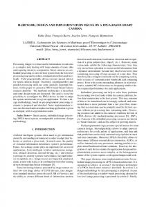
2. Description of testbed For illustration we will use a simple model of a manufacturing system called “Distribution Station” (Figure 1) that consists of two mechatronic units: a feeder unit with a magazine of workpieces and a pusher; and a simple manipulator (transfer unit) that takes workpieces from the feeder (left position) and brings them to the opposite position (called next position or right position), where they are supposed to be taken by other automated machines.
In addition to the mechatronic models of machines, the station includes a small panel with buttons RESET, START, STOP, and ACK(nowledge). The buttons have no memory, so each button generates a logical one (TRUE) value as long as it is pressed and zero otherwise. Thus, a short push on a button generates a pulse. The buttons are lit underneath by LEDs that also can be controlled, i.e. set by the control device as needed. The highlighted status of buttons may indicate that they are enabled. State chart of a (centralized) controller of the distribution station is shown in Figure 2. The state chart can be quite trivially converted to executable code in one of the standard programming languages of programmable logic controllers, such as ladder logic or sequential function charts. However, in this work we are looking for control architectures in which each of the mechatronic units has their own controller communicating with controllers of other units. The controllers can be created from scratch, or can be originated in an existing centralized controller. The latter can be given in some abstract form, like state chart, or as PLC code, for instance, represented in the ladder logic language. The important problem of migration from PLC-based control to distributed controllers will be addressed in Section 6.
3. Architecture for distributed control Figure 1. Mechatronic system for work piece storage and transfer [11].
The “Distribution Station” is a part of a bigger manufacturing system model, which is a chain of several stations representing different stages of a manufacturing process.
There are many possible approaches to the design of distributed controllers. Obviously a controller of a mechatronic unit that collaborates with other units (and their controllers) needs to combine pure control sequences (as any local controller) and communication with other controllers. The communication can be implemented using a custom-made proprietary protocol or using services of an existing one. It is not very difficult to create distributed control for a concrete system of limited complexity. Our intention, however, is to investigate the approaches that would allow more flexibility in building system from mechatronic units like from blocks with autonomous control. For that we propose using of a layered architecture with three layers, as illustrated in Figure 3.
Figure 3. Layers of the distributed control architecture.
The layers have the following functions: Figure 2. State chart of the centralized controller.
1. The application layer can include sequential centralized or local decentralized controllers, implementations of intelligent (agent) algorithms, etc. 2. The operations layer implements set of operations defined for mechatronic units along with their implementation sequences. 3. The sensors/actuators layer – provides direct access to sensors and actuators of the physical object. Functions of a layer use services of the layer located directly below in the hierarchy. Some implementations can mix functions of the layers, e.g. an operations layer controller can also encapsulate functions of the sensor/actuator layer.
4. From centralized to distributed Some of the scenarios presented in the introduction may require re-implementation of an existing automation system with centralized control by a system with distributed control. Depending on the available input, the proposed solution can be essentially different. The behaviour of our sample object is captured in form of the process activity diagram in Figure 4.
Figure 4. Process activity diagram.
The process includes well separatable sequences of actions of the feeder and of the transfer units. The sequences are partially concurrent (e.g. RETRACT and TO_MAG). As applied to our example, the idea of distribution consists in “splitting” of the centralized control state chart, and adding synchronisation of the processes. We suggest a simple inter-object interface and protocol that is as follows. Each distributed controller is designed so that it attempts to perform operations as soon as they are not blocked by the controllers of other objects. This implies that the controllers have to be at least “aware” of the presence of other objects around and of the operations they perform. The interface is based on the mutually exclusive access to the areas where mechanical parts can clash. In our example such an area is the "End position" of the FEEDER unit where the workpiece is picked up by the TRANSFER unit. Access to such shared areas can be implemented by standard mutual exclusion algorithms, such as semaphore-based central algorithm, or distributed Ricart and Agrawala algorithm [5]. In this paper, for the sake of
simplicity, we are using Boolean variables passed from one controller to the other.
Figure 5. Signal interface of distributed controllers in the external blocking approach.
The distributed controllers interface each other as illustrated in Figure 5 using the implementation of the protocol as follows. Some actions of each mechatronic unit have guard conditions “allowed by left or right neighbour” (LEFT OK/RIGHT OK). The guard conditions are set by the corresponding mechatronic units located on the right/left (if any). This approach assumes a linear order of connections of mechatronic units in the production process, but it can be easily extended for the general case of multiple connections (where mechatronic units are in the nodes of an arbitrary graph). As seen from Figure 5 this approach fits well to the hierarchical structure of mechatronic systems. Our sample system (called as a whole “Station Distribution”) has a right neighbour “Sorting Station”. The stations interface each other exactly in the same way as their components, i.e. using permissions from the left or right neighbour. In Figure 5 the permission from the right neighbour is passed down to the component controller of the transfer station, which is physically interacting with the Sorting Station. If no neighbour station is present, then the permission is set to the constant “TRUE” as it is the case in our example for the left neighbour of the distribution station and the Feeder unit. The detailed implementation of the Distribution Station controller that consists of FEEDER and TRANSFER controllers communicating via common Boolean variables is presented in form of concurrent state charts in Figure 7. Confronting the controllers from Figure 7 with the layers description in Figure 3, one sees that the controllers implement the application layer functionality directly interacting with the sensor/actuator layer.
5. Function block implementation The Function Block standard IEC 61499 aims at the distributed control as the main application area. The standard provides several structures for encapsulation of distributed controllers and design of distributed systems. The detailed description of the standard is far beyond the scope of this paper and we refer the reader to [8].
Figure 7. Distributed algorithm that uses the permit/lock protocol via common variables.
connected to the event input IN_CMD of the TRANSFER controller and vice versa. 2. The data inputs LEFT_OK, RIGHT_OK are associated with event IN_CMD, and the data outputs ALLOW_LEFT, ALLOW_RIGHT are associated with the event OUT_CMD. The output event needs to be issued every time one controller changes the block/permit variables. 3. The controllers’ State Charts are implemented as ECCs of the corresponding function blocks (shown in Figure 8 and Figure 9).
Figure 6. Decentralized control of the object.
In particular a Basic Function Block of IEC 61499 is a component model that is specified by its input/output interface, execution control chart (ECC), algorithms associated with the states of ECC and internal variables. The ECC is a state machine with a semantic similar to that of Harel state charts. The ECC semantic seems to fit well to representation of state charts of controllers like shown in Figure 2 and in Figure 7. The decentralized controller can be implemented in IEC 61499 function blocks with minor modifications as shown in Figure 6. The features specific to the function block implementation, if compared to the state charts, are as follows: 1. The inter-controller communication is implemented via passing event and data signals. Thus, the event output OUT_CMD of the FEEDER controller is
Figure 8. Sequential controller of the FEEDER.
4. Values of the variables are assigned in the algorithms, most of which set/reset just one variable. The algorithms have self-explanatory names, for example the algorithm TO_MGZ1 consists of one
operator: TO_MGZ:=true; and TO_MGZ0 of: TO_MGZ:=false; The controllers receive the values from the sensors in the event-driven manner through the service interface function block INPUTS of type nm_inputs and send the output values to the function block OUTPUTS of type nm_outputs. The function block INPUTS issues the event output CHG at any change of the input bits. This event output is connected to the event inputs SENS of feeder and transfer controllers. Thus, the controllers will be activated at any input change. The buttons are also connected to Boolean input signals, however they are converted to events by means of function block E_R_TRIG, that detects “rising edge” of a Boolean variable and issues the corresponding output event.
layer (MASTER) and the operation layer (CTL_FEED and CTL_TRANS).
Figure 10. Distributed control following the mastercontroller approach and implemented in IEC 61499.
6.2. Multi-layered distributed controlles The “no-master controller” pattern with Boolean locks, discussed in the previous section, can be redesigned in the similar Application-Operations manner as illustrated in Figure 11. Function blocks FEEDCTL_H and TRANSCTL_H are the application layer controllers of feeder and transfer respectively. CTL_FEED and CTL_TRANS are their operation layer controllers.
Figure 9. Sequential controller of the TRANSFER unit.
6. Other implementation ideas 6.1. Distributed Control with Master Controller Although the example shown above proves the possibility of decentralized autonomous control without any external coordination, in many real situations the use of a master controller is unavoidable. In our architecture the master controller belongs to the application layer and uses services provided by the controllers of mechatronic units implemented on the “Operations” layer. Such controllers have standardized event inputs corresponding to their operations and the outputs named according to their ECC states. They are quite different from the controllers shown in Figure 7 . The master controller encapsulates the desired sequence of operations of the lower level controllers. It sends events to the local “operations” implementing function blocks, when a certain operation needs to be executed. The Function Block network in Figure 10 implements the master controller approach divided on the application
Figure 11. FB implementation of distributed control with functionality split across the application and operations layers
Note that the connection between FEEDCTL_H and TRANSCTL_H is implemented by adapter connection based on the adapter type BLOCK shown in Figure 12.
Figure 12. Adapter BLOCK used as a communication interface between controllers of neighbouring objects.
6.3. Migration from PLC - IEC6113 The problem of development of distributed controllers in IEC 61499 equivalent to the existing PLCs has great practical importance for the successful deployment of the new standard. The migration of PLC controllers to IEC 61499 has been already addressed, in particular by Hussain and Frey in [7]. That work, however focuses on the migration of centralized controllers to IEC61499. Besides, it assumes that the abstract controller description in form of Signal Interpreted Petri Nets (SIPN) is given for the whole plant as a source for the migration. This assumption simplifies the task and allows for designing of Function Blocks implementing the sequential logic captured in SIPN. The coordination of the distributed processes was done yet in the central controller for the whole plant, under some assumptions about rigid sequencing between some processes. In some situations, however only the PLC code is given and no higher level description exists. In addition, if a distribution is desired, one can assume to be provided with the division of inputs and outputs between the distributed parts of the plant. In such a case the best would be to re-engineer the state chart of the controller given its PLC code. How to do that was shown by Krogh and Falcione in [6] for ladder logic diagrams. However no one guarantees that the re-engineered state chart would be as useful and descriptive as the original state chart. Another migration idea will be discussed in the next section.
Controller of the “Distribution station” in ladder diagram language is shown in Figure 13 (the figure shows only a part of the controller). Pure ladder diagrams are equivalent to Boolean functions and can be easily represented by a combinatorial logic circuit. The diagrams used in the logic control usually are a mix of pure ladder elements and functional elements such as triggers, timers, etc. This is also the case in the controller shown in Figure 13. The equivalent solution in terms of IEC 61499 Function Blocks can be done in a variety of ways. The way shown below might look quite strange, but it has some practical benefits that will be discussed further.
6.4. “Straightforward” ladder to FB transformation To illustrate the idea of “straightforward” migration from PLC code (say, ladder logic) of the centralized controller to a distributed function block application.
The idea of the method is to make a network of function blocks equivalent to the ladder circuit and activated by an external event issued at each update of the inputs. Part of the function block network equivalent to the ladder circuit is shown in Figure 14. The function blocks E_AND, E_OR are equivalent to the logic gates AND, OR. The only difference with the usual logic gate blocks is that they have event input REQ, activating the operation. The block SR_TRIG implements a trigger whose switching is also driven by the event input REQ. The function block IO represents an interface to the input and output process data. When the inputs are updated it issues the event CNF that activates the execution of the function block network. The IO block can be implemented as a composite function block that encapsulates previously used nm_inputs and nm_outputs Function Blocks. Once the function block network as in Figure 14 is created, it can be easily mapped on a distributed topology of devices following the idea from [8] illustrated in Figure 15.
Figure 13. Fragment of the ladder diagram representing the controller of the model.
Figure 14. Straightforward implementation of Boolean logic by an event-driven Function Block network.
Figure 15. Mapping of a function block network to distributed
devices:
execution
semantic
preserved
thanks to the event-based communication [8].
For example, we will separate out the controller of the HMI pannel and move it to another device. The first step in the distribution is to separate the inputs and outputs of the panel as shown in Figure 16 where the input/output function block IO was substituted by two blocks IO1 and IO2 corresponding to one byte of inputs and one byte of outputs each.
Figure 16. First step of the distribution process is separation of inputs and outputs.
Then, the function blocks of the application have to be mapped to the corresponding devices starting from IO1 and IO2 and the communication function blocks have to be inserted in the points where the connections cross the borders of devices. The reader may wonder why such a low-level representation of Boolean logic as in Figure 14 may be practical when ladder logic diagram can be easily encapsulated to a Basic function block’s algorithm? The reason is as follows: One of the most popular function block implementations is Function Block Development Kit of
Holobloc Inc. [9]. This tool compiles function block types to Java classes. Thus, if it is used in conjunction with an embedded control device, like Netmaster [10], every change in a basic function blocks requires to upload the re-compiled class file to the embedded device. Since the run-time part of FBDK does not support dynamic class upload, it leads not only to the need to shut down the current process, but also to the need to substitute the whole run-time library of function blocks (FBRT). The procedure is too complex to be performed at the factory floor. However, system configurations in FBDK do not need to be re-compiled. For example, the system configuration from Figure 14 can be modified in the FB editor running on a PC and then remotely re-started in the embedded devices without any re-compilation. So, the maintenance personnel would be able to modify the program and immediately test it on a real physical system.
7. Conclusion The design of distributed controllers has many similarities with the design of distributed computer applications. When the communication between the controllers is concerned, three approaches are possible: - Design a proprietary application-layer protocol; - Implement (and possibly modify) an existing protocol; - Use services of an existing protocol implementation; In this paper we have addressed two first approaches. We have illustrated that the concept of Basic Function Blocks of IEC 61499 was specifically designed to implement certain separation of concerns: the protocol issues are implemented in ECC, while the atomic control actions are implemented in algorithms. Thus, the Function Block applications provide sufficient means for implementation of distributed controllers. The work will be continued towards the development of more formalized design methodologies and supporting tools that would allow easy distribution of centralized control algorithms and their implementation by means of IEC 61499 Function Blocks.
8. References [1] Sunder, C.; Zoitl, A.; Strasser, T.; Favre-Bulle, B. Intuitive control engineering for mechatronic components in distributed automation systems based on the reference model of IEC 61499,; Industrial Informatics, 2005. INDIN '05. 2005 3rd IEEE International Conference on 10-12 Aug. 2005 Page(s):50 - 55 [2] Ferrarini, L.; Veber, C.; Lorentz, K.; A case study for modelling and design of distributed automation systems, Advanced Intelligent Mechatronics, 2003. AIM 2003.
Proceedings. 2003 IEEE/ASME International Conference on Volume 2, 20-24 July 2003 Page(s):1043 - 1048 vol.2 [3] IEC61499 - Function blocks for industrial-process measurement and control systems - Part 1: Architecture, International Electrotechnical Commission, Geneva, 2005 [4] IEC61131 - International Standard IEC 1131-3, Programmable Controllers - Part 3, International Electrotechnical Commission, 1993, Geneva, Switzerland [5] Couloris G., J. Dollimore, T. Kindberg, Distributed System: Concept and Design, Addison-Wesley, 2005 [6] Falcione, A., and Krogh, B., Design recovery for relay ladder logic, IEEE Control Systems, 13(2):90—98, 1993. [7] Hussain T. and Frey G.: Migration of a PLC Controller to an IEC 61499 Compliant Distributed Control System: Hands-on Experiences, IEEE Conference on Robotics and Automation (ICRA 2005), Barcelona, April, 2005 [8] Hanisch H.-M. and Vyatkin V.: Achieving Reconfigurability of Automation Systems by Using the New International Standard IEC 61499: A Developer’s View, The Industrial Information Technology Handbook, CRC Press, October 2004 [9] Function Block Development Kit, www.holobloc.com [10] Netmaster controllers, Elsist s.r.l., www.elsist.it [11] Vyatkin V., IEC 61499 Function Blocks for Embedded and Distributed Control Systems Design, 264 p., ISA, USA, 2006