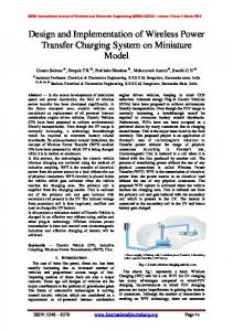
1
Design and Implementation of AC/DC Active Power Load Emulator Ahmed Elsayed, Student Member, IEEE, Ahmed Ebrahim, Student Member, IEEE, Habeeburrahman Mohammed, Student Member, IEEE and Osama A. Mohammed, Fellow, IEEE Energy Systems Research Laboratory (ESRL), Florida International University, Florida, USA. Abstract— This paper introduces the design and implementation of a programmable AC/DC active load emulator that has the capability to emulate a very wide range of active power with the ability to change the power with small steps to give flexible load emulation. The developed load emulator can mimic the real time active power characteristic of daily load pattern which can be used in testing power management algorithms. It gives an easy tool to test the performance of the utility grid by emulating different load profiles like random residential loads and electric vehicle charging stations. Furthermore, it can be used in the shipboard power system to emulate pulsated load. A friendly user GUI is developed in LabVIEW to facilitate the control of the load emulator. Actual hardware implementation steps are explained in details. The initial experimental results show the validity of the developed active power emulator and its capability to mimic different load profiles. Index Terms—Active power load emulator, labview, pulsed load.
I. INTRODUCTION
I
the demand of electrical energy with the rapid upgrade of the power system equipment, more penetration of renewable energy and the existence of new types of unusual loads such as electric vehicles require new flexible methods for modelling and emulating such loads. Furthermore, the energy crisis and recent blackouts are driving intensive research in the area of power systems and smart grids. Thus, emulating different power system scenarios and variety of load behaviors became mandatory. The development of a reliable and robust load emulator is a necessary tool for the following purposes; 1) dynamically emulate different real power flow situations, 2) testing or investigating the behavior of new equipment such as generators or power supplies, 3) discovering the effect of emerging special loads to the power system such as pulsed loads or bulky charging of electric vehicles, 4) mimicking the real time active power characteristic of the daily load pattern which can be used in testing power management algorithms. There are several literatures introducing the load power emulator such as [1] which introduces regenerative two stage active load emulator using bidirectional AC/DC Converter as a grid interface. A programmable load emulator capable of NCREASING
This work was partially supported by grants for the Office of Naval Research. The authors are with the Energy Systems Research Laboratory, Department of Electrical and Computer Engineering, Florida International University, Miami, FL 33174 (e-mail:
[email protected]).
mimicking the load characteristics of a real time load data collected from smart meters presented in [2]. The presented load emulator is based on a PWM controlled converter to mimic the reactive power and additional DC-DC converter to mimic the active power. Methods for developing load emulators capable of emulating electrical loads by using voltage source inverters (VSIs) connecting to three phase AC grid are presented in [3], [4]. The main concept of these methods is controlling the VSI by a closed loop current controller to control the duty cycle based on a reference current signal to withdraw current level from the grid matching the reference value. A three phase load emulator (TPLE) controlled by OneCycle Control (OCC) current loop technique generating high frequency switching signals to control bidirectional AC/DC converter introduced in [5]. An AC load emulator which is based on two back to back single phase PWM converters is presented in [6]. The authors of [7] presented another AC load emulator based on AC-DC-AC power converter topology and a z-source converter. Most load emulators presented in the literature are based on costly power electronic converters which require complicated control algorithms. Although, these techniques provide an accurate load emulation, however, these load emulators can be a source of harmonics due to fast power electronic switching. This paper presents a flexible, simple, robust and low cost load emulator. This load emulator can be used for active power flow emulation in AC and DC applications. The detailed steps for the design and hardware implementation in laboratory environment are presented. The presented load emulator configuration is based on the arrangement of resistors and switching them to achieve different equivalent resistances as 60 Ω
50 Ω
5
2
4
1
40 Ω
7
8
20 Ω
1Ω
6
3
20 Ω
Voltage Source
Fig. 1. Configuration of the proposed active power load emulator.
2 showing in the following sections. This paper is organized as the following: the system description and the hardware implementation will be presented in section II, System’s control and the development of the GUI are discussed in section III. The experimental results are presented in IV, finally, the conclusion will be in section V. II. SYSTEM DESIGN AND HARDWARE IMPLEMENTATION A. System Configuration The configuration of the proposed load emulator is simple and consists of a combination of resistances with different values in a certain arrangement. The adopted topology is depicted in Fig. 1, it can be seen that eight resistances are used with different values (60 Ω, 50 Ω, 40 Ω, 20 Ω, 20 Ω and 1 Ω). By increasing the number of the used resistors, more equivalent load values can be obtained. This can significantly increase the flexibility of the emulator, however it involves more cost and increases the complexity. So, a tradeoff has to be evaluated by the designer. Also, changing the values of the used resistors can yield different combinations and load patterns. Eight controlled switches are used to alter the system’s topology. The main operation concept is based on sending control signals to the switches to change their states (on/off) and by changing their states the equivalent circuit is changing. For example, if switches 1 and 3 are on and switch 2 is off, then the 60 ohm and 40 ohms resistors are in parallel yielding an equivalent resistance of 24 ohms. In another situation, if the aforementioned switches’ positions are inverted (i.e. S1 and S3 are off and S2 is on), the 60 ohm will be in series with the 40 ohm resistor yielding an equivalent value of 100 ohm. With this combination, total load values of 256 can be achieved. The truth table and load value corresponding to each single group of states are shown in Table I. In this table, only 52 load values are shown. The other load values are omitted as some of the load combinations are lacking feasibility such as load value of one ohm which can result in a very high current. Some other values are repeated. Through this configuration and with the specified resistor values, this load emulator can emulate loads ranging from 15 ohm up to 191 ohm. B. Hardware Implementation The aforementioned configuration has been implemented in Energy Systems Research Laboratory (ESRL). This sub section provides important tips and details for students and researchers for implementing such a system. In order to achieve high power load emulation, high current GE contactors are used for switching operations. The used contactor is CR353AC3A, which is rated for 30 Amps in case of inductive load and 40 Amps for resistive load. The voltage rating is 600 AC volts [8]. It is worthy to mention that these contactors were dismantled from an old equipment. i.e. not purchased for this purpose. These contactors are controlled through a control coil (55820A) which operating voltage is 110 VAC. The existing control module is NI PCI 6025E, this data acquisition card is equipped with 16 AI ch., 2 AO, 32 DIO channels and 2-24 bit counters [9]. The voltage level of the digital output channel of
this card is (0-5VDC). Hence, it was challenging to drive the GE contactors from such a legacy card. Building a voltage matching circuit was mandatory to interface the DO channels to the control coils of the contactors. A schematic diagram of the control system is shown in Fig. 2. The control commands are initiated from a control program developed in LabVIEW environment. The control commands are sent through the PCI 6025E card to a circuit. This circuit is based on TEXAS INSTRUMENT inverting buffer module sn7406n. This module contains six inverters with open collector output [10]. This circuit can change the control voltage from a level to another since it is based on an open collector configuration. The desired output voltage is connected to the VCC terminal, then two inverting terminals are connected in series. This implies that the output signal will be the inversion of the inversion of the input one which will be the same. However, the voltage level will be the same as that of the VCC, regardless the voltage level of the input signal. In our case the input signal level is 5 VDC (forwarded from the PCI card) and the output will be +15 VDC. It should be noted here that this module is sensitive to voltage variations, so, a voltage regulator LM 7815 is connected to the input to regulate the output voltage around 15 V level. Up to this stage, the control signal sent from the NI PCI DAQ is elevated to the 15 V level, this signal is used to drive another relay which is G2RL-14E. The control voltage of this relay is 15VDC and its rated operating voltage is up to 250 VAC. A 110 VAC source is connected to the NO contact of this relay while the control coil of the contactor is connected in series (refer to Fig.2). Upon receiving an activation signal, the NO contact of the auxiliary relay (G2RL-14E) will close allowing current to pass to the control coil of the contactor to energize it. Through two stages, the control voltage is increased from 5V DC to 15VDC and from 15VDC to 110 VAC. This control circuit can be utilized for many different applications such as motor driving systems. Fig. 3 shows the switching array after the implementation with the eight contactors. The control voltage matching circuit is shown on the top. Based on the voltage rating of the used contactors, the developed load emulator can work up to 600V for AC operation. By adopting the method provided in [11] the AC contactor can be used safely for DC applications. It was suggested to connect the three phase AC contactor contact pairs in series to eliminate the spark in case of DC operation as shown in Fig. 4. However, it is highly recommended to operate the contactor at a reduced DC voltage up to 400 VDC [12]. Despite the fact that the utilized switches are rated for operation up to 40 Amp in case of resistive loads (which is the case here), this current level cannot be reached. Since, the current rating of the load emulator is mainly governed by the power dissipation of the used resistors which is determined by I 2×R. Based on the used resistors power ratings, allowed temperature rise and number of resistors, it is determined that the maximum current is 15 Amps. The used resistors are from the ceramic type. III. CONTROL SYSTEM The
control
system
is
implemented
in
LabVIEW
3
TABLE I TRUTH TABLE FOR LOAD EMULATOR SWITCHES CONTROL No.
S1
S2
S3
S4
S5
S6
S7
S8
Req
No.
S1
S2
S3
S4
S5
S6
S7
S8
Req
1
1
1
1
1
0
1
1
0
15.2
27
0
0
1
1
0
0
1
1
80
2
1
1
1
1
0
0
1
1
20
28
0
0
1
1
0
0
1
0
81
3
1
1
1
1
0
0
1
0
21
29
1
0
0
0
0
1
1
1
90
4
1
0
1
1
1
1
1
1
24
30
1
0
0
0
0
1
1
0
91
5
1
0
1
1
1
1
1
0
25
31
1
0
1
0
0
1
0
1
94
6
1
1
1
1
0
1
0
0
35.2
32
1
0
1
0
0
1
0
0
95
7
1
0
1
1
0
1
1
1
38.2
33
0
0
1
1
1
0
0
1
100
8
1
0
1
1
0
1
1
0
39.2
34
0
0
1
1
1
0
0
0
101
9
1
0
0
0
1
0
1
1
40
35
0
0
1
0
0
1
1
1
110
10
1
0
0
0
1
0
1
0
41
36
0
0
1
0
0
1
1
0
111
11
1
0
1
1
0
0
1
1
44
37
1
0
1
0
1
0
0
1
114
12
1
0
1
1
0
0
1
0
45
38
1
0
1
0
1
0
0
0
115
13
1
1
1
0
0
1
1
1
50
39
0
1
0
1
0
0
1
1
120
14
1
1
1
0
0
1
1
0
51
40
0
1
0
1
0
0
1
0
121
15
1
0
0
1
0
1
1
1
54.2
41
0
0
1
0
0
1
0
1
130
16
1
0
0
1
0
1
1
0
55.2
42
0
0
1
0
0
1
0
0
131
17
1
0
1
1
0
1
0
1
58.2
43
0
1
0
1
0
1
0
1
134.2
18
1
0
1
1
0
1
0
0
59.2
44
0
1
0
1
0
1
0
0
135.2
19
0
0
1
1
1
1
1
1
60
45
0
1
0
1
0
0
0
1
140
20
0
0
1
1
1
1
1
0
61
46
0
1
0
1
0
0
0
0
141
21
1
0
1
1
0
0
0
1
64
47
0
0
1
0
1
0
0
1
150
22
1
0
1
1
0
0
0
0
65
48
0
0
1
0
1
0
0
0
151
23
1
1
1
0
0
1
0
1
70
49
0
1
0
0
0
1
0
1
170
24
1
1
1
0
0
1
0
0
71
50
0
1
0
0
0
1
0
0
171
25
1
0
1
0
0
1
1
1
74
51
0
1
0
0
1
0
0
1
190
26
1
0
1
0
0
1
1
0
75
52
0
1
0
0
1
0
0
0
191
LabView Control Program and GUI
NI PCI6025E
5V-DO (8 ch.)
DC Supply
SN7406
To Dynamic Loop Emulator Power Circuit
Vcc = LM7815 15VDC
+15V-DO 110V ( 8 channels) AC
G2RL-14E
Output signal (15 VDC level)
Input signal (5VDC level)
Inverting Buffer Circuit
GE-40 AMP High Power Contactor
Fig. 3. The implemented witching array and the control circuit. Fig. 2. Schematic diagram for the control system.
environment, also, a uses friendly GUI is developed to ease the control of the system. The control signals are sent in 8×1 vector with binary elements. Three nested loops with case structures are adopted to allow the user to select which load pattern to
emulate. These load patterns are as the following: 1) Random Load pattern; in this case the software starts to generate random numbers and select random combinations. This pattern is useful in emulating random and unexpected loads. Moreover, the user can set an upper and lower load
4
12
10
Current (Amp)
8
6
4
2
Fig. 4. Contactor connection for DC, three poles in series [11].
0 0
10
20
30
40
50
60
70
80
90
100
Time (min)
2) User Defined Pattern; this option allows the user to define his own pattern and emulate it. The user can input reference load value and duration for each load step. Then this load pattern can be repeated infinitely. 3) Pulsed load; it is a load that is characterized by a very high amplitude in a short time duration. This type of loads exists in ship power systems [13]. Pulsed load can also refer to a high number of electric vehicles charging at the same time. Through this option, the load emulator allows the user to obtain a pulsed load profile with a specific amplitude, duty cycle and frequency. 4) User Input; the user has the capability to select the load value manually from a drop down menu. The user doesn’t have to know any information about the truth table. Simply, the user selects the desired equivalents resistance, based on a case structure, the program selects the combination that achieves the required load value. Then it sends the control signals vector to the switches.
Fig. 5. Random Load Pattern 11 10 9 8
Current (Amp)
limits so that, the generated random load values are within these limits. This increases the flexibility and the options available for the user. Further, it serves as a protection when operated at high voltage values, so lower resistance combinations can yield high current. Hence, these values can be excluded by setting a lower limit.
7 6 5 4 3 2 1 0
5
10
15
20
25
Time (min)
Fig. 6. User defined load pattern. 9 8 7
The four functions listed in the previous section namely random load patter, user defined pattern, pulsed load and user input are tested experimentally. A. Random Load Pattern In this case the LabVIEW starts generating random values and based on these values, an equivalent load value is selected randomly. During this test, the load emulator was connected to a 200 VDC supply. Fig. 5 shows the generated load pattern (current). The test was run for a continuous period of 100 minutes. For the first 25 minutes, upper and lower limits of 70 ohm and 40 ohm respectively were applied. It can be seen that the load pattern is within the specified values. After the minute 25, the limits were removed allowing the control to generate value over the entire range (15 ohm to 191 ohm). Running the
Current (Amp)
6
IV. EXPERIMENTAL RESULTS
5 4 3 2 1 0 0
5
10
15 20 Time (min)
25
30
35
Fig. 7. Pulsed load profile with different duty cycles.
developed load emulator continuously for 100 minutes indicates the high reliability and rigidity.
5 B. User defined Pattern In this option the user is asked to input different load steps and the time duration for each step. This allows the user to create a flexible load pattern based on his needs. An example of a load pattern is emulated and shown in Fig.6. It can be seen that the load pattern can be repeated any number of times and its time scale can be adjusted flexibly based on the user needs. This can be useful in emulating daily load patterns for residential areas or in smart meter applications. C. Pulsed Load Pulsed loads are considered very crucial in a sense that they cause high voltage and frequency fluctuations in the system they are connected to. Their existence is stressful on the generators and their mitigation methods have attracted more attention recently. Therefore, the emulation of such tough characteristics is of high importance. Simply, the user can select a pulsed load option and set the frequency, amplitude and duty cycle. The load emulator will start to emulate the specified load pattern continuously. In Fig. 7, and emulated pulsed load pattern is shown, the pattern is divided into three periods. During the entire test the amplitude was kept constant at 8 Amps. In the first period, from the beginning of the test up to min 20, the frequency was 0.1 Hz and the duty cycle is 50%.
operator commands. In order to validate the endurance of the developed load emulator it was tested over a wide range of current from 1 Amp to 13 Amps for 90 minutes. No problems were detected except a rise of resistors temperature but within the permitted limits. A zoom in for the test data from minute 70 to minute 90 is shown in Fig. 9. V. CONCLUSION The design and implementation details of a simple, low cost and reliable load emulator are presented in this paper. Unlike the other load emulators that are presented in literature, the proposed emulator is clean and harmonic free. Since most of these load emulators encounter fast power electronic switching, they add more harmonics to the system. The developed load emulator is based on a simple topology with eight resistors and eight switches. It is capable of emulating random load patterns, pulsed load profiles with different duty cycle and frequency and any profile defined by the user. The load emulator was tested for elongated periods with current up to 13 Amp. The experimental results showed the reliability and effectiveness of the proposed design. REFERENCES [1]
14
Current (Amp)
12
[2]
10 8
[3]
6 4
[4]
2 0 0
10
20
30
40
50
60
70
80
90
Time (min)
[5]
Fig. 8. Load profile based on user selection. [6]
Current (Amp)
5 4
[7]
3 2 1 70
72
74
76
78
80
82
84
86
88
90
[8]
Time (min)
Fig. 9. A zoom in for test data between minutes 70 and 90.
From minute 20 to minute 32, the frequency kept constant but the duty cycle is reduced to 20%. The third stage starts at the minute 32 and ends at the minute 35 (the end of the entire test). In this stage the duty cycle is reduced to 10% and the frequency is increased to 0.2 Hz. This illustrates the operation flexibility provided by the proposed load emulator. D. User Input In this operation option the user is manually controlling the load values in the real time. The load profile shown in Fig. 8 is selected manually by an operator. The graph reflects the flexibility of the load emulator and its quick response to the
[9] [10] [11]
[12]
[13]
Hadi Y. Kanaan, Maxime Caron and Kamal Al-Haddad “Design and Implementation of a two –stage Grid-Connected High Efficiency Power Load Emulator,” IEEE Transaction on Power Electronics, vol. 29, No. 8, August 2014. Ahmed A. Mohamed, Osama A. Mohammed “Real-Time Load Emulator for Implementation of Smart Meter Data for Operational Planning,” Power and Energy Society General Meeting, 2012 IEEE conference. Y. Srinivasa Rao, Member, Mukul C. Chandorkar “Real –Time Electrical Load Emulator Using Optimal Feedback Control Technique” IEEE Transaction On Industrial Electronics, vol. 57, No. 4, APRIL 2010. Y. Srinivasa Rao, Member, Mukul C. Chandorkar “Electrical Load Emulator for Unbalanced Loads and with Power Regeneration” Industrial Electronics (ISIE), 2012 IEEE International Symposium. K. Smedley, A. Abramovitz, F. Maddaleno, G. Rella, S. Primavera “One Cycle Controlled Three-Phase Load Emulator” Applied Power Electronics Conference and Exposition (APEC), 2011 Twenty-Sixth Annual IEEE Conference. F. Li, Y.P. Zou, C.Z. Wang, W. Chen, Y.C. Zhang, J. Zhang, “Research on AC electronic load based on back to back single-phase PWM rectifiers,” Applied Power Electronics Conference and Exposition, APEC 2008, 24-28 Feb. 2008, pp. 630 – 634. Xupeng Fang, Chunjie Li, Zhiqiao Chen, Liangbing Guo “Z-Source Converter-Based Feedback Type Electronic Load” International Conference on Automation and Logistics August 16-20 2010, Hong Kong and Macau. Available Online: http://livewiresupply.com/pdfcatalog/ ATTACHMENTS/DIR100004/GENELEC00003_5_3_5_1.pdf. Available Online: http://www.ni.com/pdf/manuals/370719c.pdf Available Online: http://www.ti.com/lit/ds/symlink/sn7406.pdf D. Salomonsson, and A. Sannino, “Low Voltage Dc Distribution Systems for Commercial Power Systems with Sensitive Electronic Loads,” IEEE Trans. Power Delivery, vol. 22, no. 3, pp. 1620–1627, Jul. 2007. A. Sannino, G. Postiglione, and, M. H. J. Bollen “Feasibility of a DC Network for Commercial Facilities,” IEEE Trans. Industry Applications, vol. 39, no. 5, pp. 1499–1507, Sep. 2003. A. Mohamed, V. Salehi, O. Mohammed, “Real-Time Energy Management Algorithm for Mitigation of Pulse Loads in Hybrid Microgrids,” IEEE Transactions on Smart Grid, vol. 3, no. 4, pp. 19111922, Dec. 2012.