used for controlling the servo motors and computing the joint angels by kinematic .... 18-DOF six-legged robot and controls all servo motors via serial port. ..... group of leg lifted down and all feet are free as seen in 10 numbered view. All steps ...
ISSN: 2278 – 1323 International Journal of Advanced Research in Computer Engineering & Technology (IJARCET) Volume 5, Issue 6, June 2016
Design and implementation of an 18-dof six-legged robot: ABR1 Hüseyin Oktay ERKOL, Hüseyin DEMİREL Abstract— In this study, a six-legged robot is designed and implemented for real time walking over difficult terrains. A remote control and tracking interface program is designed to control robot in all direction and tracking the sensor data. Servo motors controlled via serial port are used as joint actuators. An FPGA based hardware designed as single chip is used for controlling the servo motors and computing the joint angels by kinematic calculations. In this way, load on the central processor is reduced and a low cost DSP used for executing the walking algorithm developed for producing the feet positions for walking on rough terrain. In addition, the mess of cable is reduced by using the FPGA based hardware and servo motors controlled via serial port. The robot has infra-red sensors for object detecting, force sensors for sensing the contact with ground and radio modules for wireless communication with computer. The success and performance of the robot is tested by simulations and real world experiments. Index Terms— Co-processor, FPGA, gait generation, man-machine interface, six-legged robot, walking algorithm.
I. INTRODUCTION Animals and their natural abilities have been always interesting for people and it has been tried to make machines like them. There are many studies like bipedal robots, dog robots, insect robots and many other types. Legged robots offer superior mobility over natural terrain against wheeled or tracked robots because of they don‟t need a continuous contact with a surface for balancing and movement [1,2]. They have also disadvantages like slow motions and complex control systems when compared with wheeled or tracked robots. Generally more legs mean better adaptation capability, but lead to more complex control systems [1,3]. Six-legged robots are seemed a good choice when considered control complexity and adaptability in legged robots [1]. Various studies about six-legged robots are reported in literature. Candini et al designed a six-legged robot in 2009 [4]. The robot has 2-DOF legs and joints are controlled by analog servos. It has sensors for measuring the pressure and current. It has also a radio module for communication with the computer. A leg control circuit is used for each leg and a central controller used for interconnection. Kinematic
Manuscript received June, 2016. Hüseyin Oktay ERKOL, Department of Mechatronic, Faculty of Engineering, Karabuk University, Karabük, Turkey Hüseyin DEMİREL, Department of Electrical and Electronics Engineering, Faculty of Engineering, Karabuk University, Karabük, Turkey
computations are not used and a rule based walking algorithm is used. Pa and Wu were developed a robot like one Candini et al designed in 2012 [5]. The robot has different type of sensors for measuring distance, temperature, accelerating and has a radio module. A man-machine interface was developed to control the robot and to show all sensor data in the interface. It has also 2-DOF legs and kinematics was not used. It is aimed to develop a low cost explorer robot in the study. Chen et al developed a six-legged robot with 3-DOF legs in 2014 [1]. Swing of the leg is main problem in the study. All joints controlled by analog servo motors controlled by a PID algorithm and used force sensors for sensing the contact with ground. ARM based microcontrollers are used to control each leg and a central microcontroller is used to motion planning. Total seven microcontrollers are used on the robot and a computer is used to produce motion task and sent to the central microcontroller. The robot has no wireless communication module or any other sensor types. It also has no gait generator algorithm. The robot developed by Agheli et al in 2014 [6] is similar to Chen‟s robot. The main difference is the degree of freedom of legs. This robot has five DOF legs that each one has three revolute joints and two prismatic joints. It is aimed that the legs shrink when needed. In this way the robot has variable leg lengths. In this study a six-legged robot is developed. It has six legs each one is 3-DOF. Three DOF is the minimum degree of freedom for walking to all direction in narrow environments [7]. The robot has infrared (IR) sensors to detect objects, and force sensor for sensing the contact with ground. It has also a radio module for communication with computer. A man-machine interface is developed for controlling the robot, tracking and using the sensor data. A walking algorithm is developed for the robot. The algorithm can produces sequenced feet positions as output for balanced motion when walking forward, walking back and turning right/left. The feet positions are converted to joint angels and sent to the servo motors by FPGA based hardware. In addition the algorithm has the ability sensing the ground contact and can produce the outputs on rough terrain. The study presented here is an extension of our earlier work [8]. In the study, we developed hardware on FPGA for solving the kinematic equations of six-legged robots. FPGAs have a wide area of usage like signal and video processing, control algorithm and etc. in robotics. Co-processor design and application is one of them [9–11]. Kinematic calculations are complicated and another calculation unit is needed, especially with the increase in the degree of freedom and when needed to get desired accurate results [8]. The
www.ijarcet.org
1756
ISSN: 2278 – 1323 International Journal of Advanced Research in Computer Engineering & Technology (IJARCET) Volume 5, Issue 6, June 2016 designed hardware has serial ports and a co-processor. There are other studies about FPGA based hardware for legged robots. Barron-Zambrano et al developed an FPGA based controller and applied on a simple six-legged robot in 2012 [12]. In the study, Central Pattern Generators (CPG), a neural network based method, is used to produce gaits. A soft processor and C based software are also embedded on the FPGA. The hardware is designed for servo motor controlled by PWM signals. Lara-Nino et al improved this hardware by adding a camera and made an educational robot platform in 2014 [13]. Spenneberg et al used an FPGA to develop an eight-legged robot [14]. In the study, PID controllers for each motor and the hardware for processing the sensor data are embedded on FPGA. A microcontroller is used for behavioral control and all other processes. The FPGA hardware used in this study has serial ports for taking the command and controlling the servo motors and a co-processor for computing the joint angles. It takes the commands via serial port, calculates the joint angels for 18-DOF six-legged robot and controls all servo motors via serial port. It is designed to use with any hardware which has a serial port like microcontroller, computer or radio module. It gives an opportunity to choose their controller in a large scale to hobbyist, educators and designers. This hardware reduces the load on the central microprocessor and accelerates the transition from design to application.
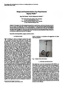
placement can be seen in Fig. 1. An extra IR sensor is placed under of the body for sensing small objects. The detailed information about the sensors is given in Section 2.2.1. The total weight of the robot is 1786 gr. The physical dimensions of the robot are given in Table 1.
Fig. 1. Views of the robot. (a) Cad design. (b) Prototype with electronics. Table 1. Robot dimensions
Parts Part 3 (a3) Part 2 (a2) Part 1 (a1) Body width Body length Total weight
Dimensions 103mm 60mm 49mm 125mm 291mm 1986gr
II. DESIGN OF THE ROBOT The design is presented as three subsections. In the mechanical design section; body design, leg design, kinematics and electronics placement are explained. In the electronic design section; mainboard, FPGA based co-processor, sensors and general hardware structure are given. In the software design section, walking algorithm and man-machine interface is explained. The FPGA based co-processor is our early study and the detail can be found in [8]. A. Mechanical design The mechanical design consists of six legs, a body and placement of the electronics components. The body houses the electronics, battery and has connections for the legs. The 3D-CAD design of the robot is given in Fig. 1.a and the prototype is given in Fig. 1.b. All mechanical parts are Plexiglas machined by a laser CNC machine and ABS made by a 3D printer. The legs are designed as three degree of freedom with revolute joints. The 3-DOF for a leg is the minimum DOF for moving to all directions in narrow environments [7]. A servo motor is placed on each joint as seen in Fig. 2. Motor 1 manipulates the leg on the body plane. Motor 2 and motor 3 move the part 3 and part 2 up and down. Force sensors are placed to foot tips to sense contact with ground. The sensor produces analog values depending on the applied force. They are used to generate suitable gaits balancing the body on the rough terrain. The detailed drawing of a leg is given in Fig. 2. In addition a head that include three IR sensors is placed to front of the robot for sensing around. The head is given in Fig. 3 and the
Fig. 2. Detailed leg structure.
Fig. 3. Head structure with sensors.
In the study, the walking algorithm produces feet positions for walking (see section 2.3.1). The kinematic equations are used for generating the joint angles depending on the feet positions. The leg design in a simplified form is given in Fig. 4. The leg has 3-DOF. Z0 is the Z axis of the reference frame. ZN (N=1, 2, 3) is the Z axis of the Joint N. Origins of the Z0 and Z1 are coincident. Z2 and Z3 are parallel and the angle between Z1 and Z2 is 90º. All joints are revolute. Denavit–Hartenberg parameters of the leg are given in Table 1 and forward kinematic equation is given in eq. (1). In the equation, the position of the foot is determined by the variables of joints. Herein, the notations ci and si are the
All Rights Reserved © 2016 IJARCET
1757
ISSN: 2278 – 1323 International Journal of Advanced Research in Computer Engineering & Technology (IJARCET) Volume 5, Issue 6, June 2016 abbreviations for cos βi and sin βi, respectively. The notations si,j, ci,j denote respectively sin(βi+βj), cos(βi+βj) [9]. The last column of the matrix in eq. (1) gives the position of the foot [15].
components in electronics are the main board, FPGA board, DSP board, radio modules, sensors and batteries. Electrical connections of the system are given in the Fig. 5. The robot prototype and the all electronics are shown in the Fig. 6.
Fig. 4. Basic leg structure and joints of the six-legged robot Table 1. Denavit–Hartenberg parameters of the leg
i 1 2 3
αi 0 90 0
ai 49mm 60mm 103mm
di 0 0 0
βi β1 β2 β3
Fig. 5. Electrical connections of the system
c23 .c1 s23 .c1 s1 c1 .(a1 a3 .c23 a2 .c 2 ) c .s s .s c s .(a a .c a .c ) 23 1 1 1 1 3 23 2 2 T30 23 1 (1) s23 c23 0 a3 .s 23 a2 .s 2 0 0 1 0 We can find the ci and si (i=1, 2, 3) by using the forward kinematic equations as follows. And after we can obtain the βi (i=1, 2, 3) angels using the ci and si using equations given above. The motion of the legs is provided using the computed βi angels using eq. (2). c3
Px 2 Py 2 a12 2.a1 . Px 2 Py 2 Pz 2 (a2 2 a32 ) 2.a2 .a3
s3 1 c3 2
c2
Px 2 Py 2 a12 2.a1 . Px 2 Py 2 .(a2 a3 .c3 ) Pz .a3 .s3
s2
a2 2 a32 2.a2 .a3 .c3 Pz (a2 a3 .c3 ) Px 2 Py 2 a12 2.a1 . Px 2 Py 2 .a3 .s3 a2 2 a32 2.a2 .a3 .c3 c1
Px Px Py 2
2
s1
,
si ci
i arctan
Py Px 2 Py 2
(2)
B. Electronic design The designed electronic hardware provides the electrical connections between the components, supplies the required electrical power and includes expansion slots. The main
The main controller of the robot is the STM32F4 Discovery Board of STMicroelectronics [16]. The board takes direction commands from the computer and sends the all sensor data to computer by the radio module. A walking algorithm is also run on the board. The algorithm generates the gaits for walking in the direction required by the direction command. For this purpose, it generates feet positions in X/Y/Z coordinates and sends to the kinematic co-processor on the FPGA via serial port. The kinematic co-processor is realized on an Altera DE0-Nano FPGA board [17]. It calculates the required joint angles for producing the required motion and sends them to the servo motors via serial port. The motion is realized in this way. The power supply of the system is 7,4V lithium-polymer battery. The servo motors use the battery voltage and it is regulated 5V and 3,3V for the other components. A mainboard is designed for the system integration. The main board has power circuits for the FPGA, DSP and the servo motors. It has also sensor circuit and data lines for serial communication with DSP, FPGA and servo motors. The input voltage is 7,4-12V and a battery or power supply can be used. It is shown in Fig. 6. The radio module used on the system is Xbee Seri 1 module produced by Digi [18]. The module has a standard serial interface for communicating the DSP. It has a range about 90m and communication speed is 250 kbps. The servo motors used on the robot are Dongbu HerkuleX DRS-0101 digital servos [19]. The motors have serial interface and internal controller. Up to 254 motors can be controlled on an only single data line. This reduces the cable mess and the load on the main controller is reduced by the internal controller of motors. The servos have 12kg.cm stall torque and 7,5-12V operating voltage. The rotor can be controlled in a 320º area. The position commands are sent in a standard data package to the servos. When the motor received the command, the internal controller moves the
www.ijarcet.org
1758
ISSN: 2278 – 1323 International Journal of Advanced Research in Computer Engineering & Technology (IJARCET) Volume 5, Issue 6, June 2016 rotor to the target angle with required speed. The serial communication signals are TTL standards. All commands needed for controlling the servo motors are produced by the co-processor realized on the FPGA. The co-processor makes the kinematic calculations of a six-legged robot. It has also serial interfaces
generates gaits, manages wireless communication and controls all electronics. Its general structure is given in Fig. 7. The algorithm takes the direction command from the computer by the radio module. There are four gait generators used to realize walking forward, back and turning to left and right. The generators produce the commands sequentially
Fig. 6. Electronics and their placement on the robot. Top view of the robot (left). Front view of the robot (right).
for controlling the servo motors and taking the commands from DSP. It takes the feet positions via serial port and computes the required joint angles. The computed angles are packaged and sent to the servo motors via a serial port. This hardware is a part of previous study and detail can be found in [8]. On the computer side, Xbee module is used with an explorer card [18]. The explorer card has a USB interface for communication with the computer. In this way any data can be sent to robot from the computer. Two types of sensor are used on the robot. One of them is infrared (IR) sensor. Three GP2Y0A41SK0F for short range (4-30 cm) and one GP2Y0A02YK0F (20-150 cm) for long range of Sharp are used [20]. Their outputs are nonlinear and changes in the range of 0-3,3V. The long range IR sensor is placed on the front of the head. Two of short range IR sensors are placed on the left and right side of the head for widening the sensing area. The angle between the long range IR sensor and the short range ones is 45º. Fourth IR sensor is placed to bottom surface of the robot body for sensing the little objects in a short range (see Fig. 6). Its direction is the same of the long range IR sensor. The second type of the sensor is the force resistive sensor produced by Interlink Electronics. It is used for sensing the contact between the foot and the ground or an object under the foot. Its resistance changes depending on the force applied on it. This sensor is used on up-side of a voltage divider circuit. The voltage change depending on the resistance is used to sense objects under the foot tip. The voltages are read by the analog to digital converters (ADC) on the DSP and used by the walking algorithm. C. Software design Walking algorithm was developed by Matlab/Simulink program and embedded on the DSP card. The algorithm
seen in Table 3 for realizing the walking. The commands are sent to the leg controller. The leg controller generates feet positions in X/Y/Z coordinates to draw the trajectory path. Each of the generated position is packaged and sent to the co-processor. The co-processor calculates the required joint angels to reach the target position by solving the kinematic equations of robot and sends the angels to the servo motors via serial port. In this way, the motion required by the leg controller is realized.
Fig. 7. General structure of walking algorithm.
All of the sensors are read and sent to the computer via radio module. The outputs of feet sensors are also used in the walking algorithm as parameters. The analog values of the force sensors are converted to “1” if it is higher than the reference and “0” if it is lower than the reference. The reference value is determined experimentally and used to be sure that the foot is unshakably contacted with ground or an object. The motion toward down is stopped when the output of the foot sensor gets higher than the reference. Because this mean the foot is contacted with the ground or an object. This sensor is read by the leg controller when the leg is only lifting down. In this way, more stable walking on rough terrain is
All Rights Reserved © 2016 IJARCET
1759
ISSN: 2278 – 1323 International Journal of Advanced Research in Computer Engineering & Technology (IJARCET) Volume 5, Issue 6, June 2016 achieved. The three foot walking style is preferred. Feet are divided in two groups in this style. The groups are shown as black and white in the Fig. 8. One of the groups is always contacted with ground. This means that the robot standing on at least three feet and this case make simply balancing the robot. During the motion, one group is lifted up and moved forward. The other group standing on the ground is moved back. This moves the body forward. After this step, feet in the fly are lifted down and the other group is lifted up and all of these steps are
leg controller for each leg and all of them run independently from each other. The algorithm also sends all senor information to the computer by radio module in every 0,1s. In this way, the operator can track the sensor data by man-machine interface. The man-machine interface was developed for controlling the robot. All direction commands can be sent to the robot and all sensor data can be read by the software. It is developed using the C# language with VisualStudio.NET. A screen view of the interface is given in Fig. 10. There are “open serial port”, “clear the graphs” and “exit” buttons on
Table 3. Commands and orders for realizing walking Order 1
Moving forward Lift up F1, F3, F5
Moving back Lift up F1, F3, F5
2
Move forward F1, F3, F5
Move back F1, F3, F5
3
Move back F2, F4, F6
Move forward F2, F4, F6
5
Lift down F1, F3, F5 Until S1, S3, S5 get „1‟ Lift up F2, F4, F6
Lift down F1, F3, F5 Until S1, S3, S5 get „1‟ Lift up F2, F4, F6
6
Move forward F2, F4, F6
Move back F2, F4, F6
7
Move back F1, F3, F5
Move forward F1, F3, F5”
4
Lift down F2, F4, F6 Until S2, S4, S6 get „1‟ * F(N) refers to FootN (N=1,2,3…6) 8
Lift down F2, F4, F6 Until S2, S4, S6 get „1‟
repeated sequentially. In this way walking is realized. The basic motions for walking forward, walking back, turning right, turning left and their orders are given in the Fig. 8. Replacement of all feet is in the same direction when walking forward or back as seen in the Fig. 8.a. and Fig. 8.b. Replacement of right feet and left feet are in reverse direction when turning to right or left as seen in the Fig. 8.c. and Fig. 8.d. During the motion, feet in the fly are moved in the same direction with walking direction. Feet on the ground are moved in the reverse direction to the walking direction. In this way the body is moved in the walking direction. The leg controller produces the required position information when each command in the Table 3 is sent to the leg controller. The structure of the leg controller is given in the Fig. 9.
Turning to right Lift up F1, F3, F5 Move forward F1, F3 and back F5 Move back F2 and forward F4, F6 Lift down F1, F3, F5 Until S1, S3, S5 get „1‟ Lift up F2, F4, F6 Move forward F2 and back F4, F6 Move back F1, F3 and forward F5 Lift down F2, F4, F6 Until S2, S4, S6 get „1‟
Turning to left Lift up F1, F3, F5 Move back F1, F3 and forward F5 Move forward F2 and back F4, F6 Lift down F1, F3, F5 Until S1, S3, S5 get „1‟ Lift up F2, F4, F6 Move back F2 and forward F4, F6 Move forward F1, F3 and back F5 Lift down F2, F4, F6 Until S2, S4, S6 get „1‟
the right side of main screen. There are direction buttons on the middle. They are “go forward”, “go back”, “turn right/left” and “stop” buttons. There are sensor information displays on the left side. Long range and three short range IR sensors values are displayed and refreshed every 0.1s. They are also displayed as graphs on the bottom of main screen. Output of the long range sensor is shown in first graph, and short range sensors are displayed together in the second graph. In addition the output of feet sensors are displayed in two separate groups. The units of all sensor values are mV. The connection between the robot end man-machine interfaces is established by the radio modules.
Pos. X
Gate Generator Pos. Y
Pos. Z
No New position?
No New position?
No New position?
Yes
Yes
Last pos.= Yes new pos. ?
Last pos.= Yes new pos. ?
No Start moving to the new X pos.
Yes Last pos.= Yes new pos. ? No
No Start moving to the new Y Pos.
Start moving to the new Z Pos.
Fig. 8. Moving directions of legs when walking
No
The leg controller compares the last position and the target position when it takes a new position command. If they are not the same, the controller moves the leg to the target position and start to wait a new position. During the position change in Z axis, if the direction is down, the controller checks the foot sensor. If there is a contact with ground or an object, the motion in Z axis is stopped. The process returns to the starting when the foot sensor sense a contact. There is a
www.ijarcet.org
Reach the No target ? Yes Stop moving
Reach the No target ? Yes Stop moving
Direction is down ?
Yes
Leg sensor gets „1‟ ?
No
Yes
Reach the No target ?
Stop moving
Fig. 9. General structure of the „leg controller‟
1760
ISSN: 2278 – 1323 International Journal of Advanced Research in Computer Engineering & Technology (IJARCET) Volume 5, Issue 6, June 2016 5-7 numbered views. Then, first group of legs is lifted up again; the body moved forward by second group of leg; first group of leg lifted down and all feet are free as seen in 10 numbered view. All steps are repeated and the object is passed successfully. IV. CONCLUSIONS
Fig. 10. Control and data tracking interface
III. SIMULATION AND EXPERIMENTAL DEMONSTRATION The walking algorithm is simulated by Matlab/Simulink program. In the simulation, a go forward command is given the algorithm and a foot sensor output as „1‟ is produced between 13-15 seconds. As seen in the Fig. 11, all steps are realizing with the same X/Y/Z positions on flat surface. At the 13th second, Z position of the leg is limited to -110mm. because the foot sensor sensed an object the height is about 30mm (140-110)=30mm). The object is passed at the next step and the Z position of the leg is get -140mm. In the experimental demonstration, a table used as a flat surface for walking and a box height is about 2cm is used as a barrier. Consecutive snapshots of walking over the barrier are given in Fig.12. Before the start of demonstration, it is no needed any parameter or tuning. The man-machine interface is started and the robot is turned on. After this step we give the walking command by the man-machine interface. After the robot takes the command, the DSP produces the feet positions and it walks over the object by sensing objects and protecting the body balance. The arrows on the snapshots show the moving direction of the legs.
In this study, a low cost, six-legged robot with 3-DOF legs was designed and implemented successfully. A man-machine interface was developed for remote control of the robot. Direction commands can be sent to the robot and all sensor data can track by the interface. The robot takes only the direction commands form the operator and produces the gaits by the developed walking algorithm. The algorithm can produce feet positions for walking on flat or rough terrain and can optimize the body position and balance using the force sensors placed on the food tips. A co-processor that developed for solving the kinematic equations of robot and can control the servo motors via serial port is used for decreasing the load on the DSP and simplifying the system. In this way, the walking algorithm is embedded on a low cost DSP board. Simultaneous localization and mapping studies are planning as a future work on the robot.
Fig. 12. Snapshots of a walking demonstration
ACKNOWLEDGMENT
Fig. 11. Simulation outputs when walking over an object
As seen in 2-4 numbered views in the Fig. 12, first group of legs is lifted up; the body moved forward by second group of leg; first group of leg lifted down and sensed the object. Then, second group of legs is lifted up; the body moved forward by first group of legs when one of the legs is standing on the object; second group of legs is lifted down as seen in
This study is supported by Department of Scientific Projects in Karabük University (No. KBÜ- BAP- 13/1DR-011). REFERENCES [1]
J. Chen, Y. Liu, J. Zhao, H. Zhang, H. Jin, Biomimetic design and optimal swing of a hexapod robot leg, J. Bionic Eng. 11 (2014) 26–35. doi:10.1016/S1672-6529(14)60017-2.
All Rights Reserved © 2016 IJARCET
1761
ISSN: 2278 – 1323 International Journal of Advanced Research in Computer Engineering & Technology (IJARCET) Volume 5, Issue 6, June 2016 [2]
[3]
[4]
[5]
[6]
[7]
[8]
[9] [10]
[11]
[12]
[13]
[14]
[15] [16] [17]
[18] [19]
[20]
S.A. a. Moosavian, A. Dabiri, Dynamics and planning for stable motion of a hexapod robot, in: IEEE/ASME Int. Conf. Adv. Intell. Mechatronics, AIM, Ieee, 2010: pp. 818–823. doi:10.1109/AIM.2010.5695819. M. Schilling, T. Hoinville, J. Schmitz, H. Cruse, Walknet, a bio-inspired controller for hexapod walking, Biol. Cybern. 107 (2013) 397–419. doi:10.1007/s00422-013-0563-5. G.P. Candini, E. Paolini, F. Piergentili, Design and manufacture of a low cost educational hexapod rover, Acta Astronaut. 65 (2009) 525–536. doi:10.1016/j.actaastro.2009.01.061. P.S. Pa, C.M. Wu, Design of a hexapod robot with a servo control and a man-machine interface, Robot. Comput. Integr. Manuf. 28 (2012) 351–358. doi:10.1016/j.rcim.2011.10.005. M. Agheli, L. Qu, S.S. Nestinger, SHeRo: Scalable hexapod robot for maintenance, repair, and operations, Robot. Comput. Integr. Manuf. 30 (2014) 478–488. doi:10.1016/j.rcim.2014.03.008. B. Klaassen, R. Linnemann, D. Spenneberg, F. Kirchner, Biomimetic walking robot SCORPION: Control and modeling, in: Rob. Auton. Syst., 2002: pp. 69–76. doi:10.1016/S0921-8890(02)00258-0. H.O. Erkol, H. Demirel, A VHDL application for kinematic equation solutions of multi-degree-of-freedom systems, J. Zhejiang Univ. Sci. C. 15 (2014) 1164–1173. doi:10.1631/jzus.C1400120. B. Siciliano, L. Sciavicco, L. Villani, G. Oriolo, Robotics, Springer, 2009. doi:10.1007/978-1-84628-642-1. Q. Zeng, K.F. Ehmann, J. Cao, Tri-pyramid Robot: Design and kinematic analysis of a 3-DOF translational parallel manipulator, Robot. Comput. Integr. Manuf. 30 (2014) 648–657. doi:10.1016/j.rcim.2014.06.002. Y. Song, H. Gao, T. Sun, G. Dong, B. Lian, Y. Qi, Kinematic analysis and optimal design of a novel 1T3R parallel manipulator with an articulated travelling plate, Robot. Comput. Integr. Manuf. 30 (2014) 508–516. doi:10.1016/j.rcim.2014.03.006. [J.H. Barron-Zambrano, C. Torres-Huitzil, H. Rostro-Gonzalez, Versatile FPGA-based locomotion platform for legged robots, in: 2012 Int. Conf. Reconfigurable Comput. FPGAs, 2012: pp. 1–6. doi:10.1109/ReConFig.2012.6417035. C.A. Lara-Nino, C. Torres-Huitzil, J.H. Barron-Zambrano, Versatile educational and research robotic platform based on reconfigurable hardware, in: 2014 Int. Conf. ReConFigurable Comput. FPGAs, 2014: pp. 1–6. doi:10.1109/ReConFig.2014.7032564. D. Spenneberg, F. Kirchner, Ambulating robots for exploration in rough terrain on future extrateresstial missions, in: 8th ESA Work. Adv. Sp. Technol. Robot. Autom., 2004: pp. 1–7. R.M. Murray, A Mathematical Introduction to Robotic Manipulation, CRC Press, 1994. STMicroelectronics, STM32F4 Discovery kit, (2015). http://www.st.com/. Altera, DE0-Nano Development and Education Board, (2015). http://www.altera.com/education/univ/materials/boards/de0-nano/unv-d e0-nano-board.html. Digi, XBee Module 1, (2015). www.digi.com. Dongbu Robot, Herkulex User Manual, (2011). http://www.sgbotic.com/products/datasheets/robotics/herkulexeng.pdf (accessed January 1, 2011). Sharp, Infrared Distance Sensors, (2015). http://www.sharp-world.com/,” IEEE Trans. Image Process., vol. 10, no. 5, pp. 767-782, May 2001. Hüseyin Oktay ERKOL is an Assistant Professor in the Department of Mechatronic Engineering in Karabuk University. He received the B.Sc and Ph.D. in Electric-Electronic Engineering.
Hüseyin DEMİREL is an Assistant Professor in the Department of Electric-Elctronic Engineering in Karabuk University.
www.ijarcet.org
1762