For example: tactile displays, electronic canes, mobile phones, laptop computers, etc. ... ETA wearable kind depend on infrared light emitting diode technique.
International Journal of Innovative Research in Engineering & Science ISSN 2319-5665 (June 2013, issue 2 volume 6)
Design and Implementation of an Electronics Travel Aid for Environment Discovery Using Infrared Technique Ali Qader Baki (1), Ibrahim Kaittan Fayyadh (2) , Aseel Ibrahim Mahmood , Farhan Lafta Rashid(3) and Muhammad Asmail Eleiwi(4) Ministry of Science and Technology-Iraq (4)
Lecture, Tikrit University, College of Engineering Mechanical Engineering Department
Abstract The goal of this paper is to design and implementation of wearable device which can be use as a guide to blind people by allowing them to imaging and response to spatial information by using IR transceiver then give an alarm as a vibration to skin by using a mobile vibrator. This vibration is give alarm to blind person to avoid obstacle, its look like sensory appendages of insects. This device can be used instead of dogs or cane to help blind people also it can be used by workers whose work in dangerous construction locations. Keyword: Electronics Travel Aid (ETA), IR System Technique, Blind Assistive Device 1. Introduction Globally, an estimated 40 to 45 million people are totally blind, 135 million have low vision and 314 million have some kind of visual impairment. The incidence and demographics of blindness vary greatly in different parts of the world. In most industrialized countries, approximately 0.4% of the population is blind while in developing countries it rises to 1%. It is estimated by the World Health Organization (WHO) that 87% of the world's blind live in developing countries [1].So Assistive devices are a key aspect in wearable systems for biomedical applications, as they represent potential aids for people with physical and sensory disabilities that might lead to improvements in the quality of life. These devices can be Wearable devices are distinctive from portable devices by allowing hands-free interaction, or at least minimizing the use of hands when using the device. This is achieved by devices that are actually worn on the body such as head-mounted devices, wristbands, vests, belts, shoes, etc. Portable devices are usually compact, lightweight, they can be easily carried (but not worn) by the user and require constant hand interaction. For example: tactile displays, electronic canes, mobile phones, laptop computers, etc. Head-mounted devices such as headsets and headbands are the most popular kind of wearable assistive devices [2]. This classification is according how use the device but according to technique its can be either Electronic Travel Aids (ETAs) or Tactile-Visual sensory Substitution (TVSS) that two different paths have been explored in the past: one consist in extending the capabilities of the cane for the blind (using ultrasound or even laser rangefinders or infrared), and converting the sensed range-data to a convenient vibro-tactile cue on the hand wearing the device [3] .The other approach uses the input from an imaging device to drive a two-dimensional haptic display (placed on the skin or even on the tongue). This approach benefits from the research on reading aids based on TVSS [4]. Our device is ETA wearable kind depend on infrared light emitting diode technique. 30
International Journal of Innovative Research in Engineering & Science ISSN 2319-5665 (June 2013, issue 2 volume 6)
2. Electronic Travel Aids (ETAs) An Electronic Travel Aid [ETA] is form of assistive technology having the purpose of enhancing mobility for the blind pedestrian. Perhaps the most widely known device is the Laser Cane, which is a regular long cane with a build in laser ranging system. The primary function of an electronic travel aid (ETA) is to detect and locate objects along the user’s pathway and provide as much information as possible to allow the user to determine range, direction, dimension, and height of objects. The main requirements for an ETA are: 1) detection of obstacles from ground level to head height for the full body width; 2) travel surface information including textures and discontinuities; 3) detection of objects bordering the travel path for shore lining and projection; 4) distant object and cardinal direction information for projection of a straight line; 5) landmark location and identification information; 6) information enabling self-familiarization and mental mapping of an environment [5]. In general the main limitations of the ETAs based on ultrasound ,reported in literature, are: the limited useful range, the difficulties of operating on highly reflective surfaces (smooth surfaces), with a low incidence angle (< 40°) and when detecting small openings due to the aperture of the emission cone of ultrasonic waves. Optical ETA systems do not suffer from these limitations, due to their shorter wavelength, however there are other difficulties such as ambient natural light or dependence on the optical characteristics of the obstacle surface (transparency or mirror-like reflection), Optical ETA have fact response because its depending on electromagnetic wave which travel with speed of light as shown in equation [1]: C=ƒ * λ ………………………...(1) Where: C is velocity of light=3*10ˆ8 m/sec , λ, wavelength of electromagnetic wave in meter, ƒ=frequency of wave in hertz. It is generally agreed that currently no ETA is available which incorporates all the required features to a satisfactory extent. Blind individuals find traveling difficult and hazardous because they cannot easily determine things are, a process otherwise known as spatial sensing. Thus the problem of mobility can be described as a problem in spatial sensing. The techniques for spatial sensing are well know, radar, sonar, and optical triangulation methods being the most common, and the latter two have been incorporated into a wide variety of past ETA designs [6]. However, there are many problems with currently available devices. First, the rangefinder technology is unreliable in its detection of step-downs or step-ups, such as curbs. Secondly, blind users find the sounds of various pitches or tactile vibrations being used to code the spatial information to be esoteric and difficult to understand. Thirdly, most blind users do not find the slight improvement in mobility performance to be worth the extra cost, and the additional worry of maintaining a complex, expensive battery operated system that must be carried around and kept track of. The device is intended to detect obstacles in front of the long cane, and also those which the cane cannot detect at all (an example is a large panel with supporting poles which are very far apart). Blind people have to be protected from the knees to the top of the head and for the width of their shoulders. The device is clipped onto the cane. Several near Infra-red beams (950 nm) are generated by collimated LEDs, in different directions and at different emission powers, to cover the protected field[7]. 3. Materials and Procedures This device consists of three circuits: Transmitter circuit, Receiver circuit and Alarm circuit (vibrator circuit). 3.1 Transmitted Circuit 31
International Journal of Innovative Research in Engineering & Science ISSN 2319-5665 (June 2013, issue 2 volume 6)
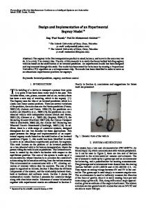
It is consist of infrared Light Emitting Diode (LED) with wavelength=940nm., and three CMOS oscillator: first oscillator generates 37.7kHz, second oscillator generate 833.33 Hz and third oscillator pulse them, we use integrated circuit (IC) have NAND gates, Figure (1) explain this meaning. The signal in figure (2) Is representing the transmitted signal. The IR detector it work with only the frequency of 37.7 kHz as a center frequency High level pulse width of 600 micro second [8].
Fig.(1): Transmitter wave form
Fig.2: Transmitted circuit 3.2 Receiver circuit The receiver circuit receives the IR ray from transmitted at wavelength of 940nm. The receiver Circuit is consist two main parts, The first part is Infrared Remote Control Receiver Circuit and the second part is Vibrator Driver Circuit with output connect to mobile vibrator, as shown in figure (5). 3.2-a Infrared Remote-control Receiver Module[IRM]: The device is a miniature type infrared remote control system receiver which has been developed and designed by utilizing the most updated IC technology that shown in figure (3). The PIN diode and preamplifier are assembled on lead frame, the epoxy package is designed as an IR filter in additional it's also contains an electronic filter as its clear in figure (4) [9].
Fig. (3) IRM- 3238S13 32
International Journal of Innovative Research in Engineering & Science ISSN 2319-5665 (June 2013, issue 2 volume 6)
Fig.( 4): Block diagram of IRM. 3.2 b Vibrator Driver Circuit This circuit consist of a mobile vibrator (working on 3.7 volt), four transistors, several piece of a resistances, one piece of capacitance and one piece of diode. This circuit act as an alarm unit to give a signal as a vibration to the skin to avoid obstacle or objects, figure (5) shown the circuit diagram for vibrator and receiver circuit .
Fig. (5) :Circuit diagram for vibrator & receiver circuit 4. Results Signals that's taken from oscilloscope which is shown in figures (6 and 7) represented a frequencies generated by transmitter circuit which contain NAND gates ICs theses frequencies modulated with IR wave that emitted from LED, we choice these frequencies (37.7 KHz) and (833.33 Hz) depending on receiver type which is response just to these frequencies because receiver circuit contains of band pass fitter.
Fig. (6) :Frequency of oscillator 1 (37.7 kHz) 33
International Journal of Innovative Research in Engineering & Science ISSN 2319-5665 (June 2013, issue 2 volume 6)
Fig. (7): Frequency of oscillator 2 (833.33 Hz). We build a circuit of receiver and transmitter on separated Ferro board and fixed their bases like a sandwich as it shown in figure (8). Front side represent receiver circuit and back side transmitter circuit. We put IRM with receiver circuit to be in front of our device. IR LED will transmit a modulated signal with mention frequency, when it hit an object or obstacle it will be reflected and scattered, IRM will sensing the reflected part from the object and convert this signal to an electrical one to operate the vibrator which give a signal to the skin.
Fig. (8) :The terminal circuit of the device.
The final shape of this device shown in figure (9); when we design it we take many construction light weight, small size, suitable shape and easy to wear and use by the blind people.
Fig. (9): The final shape of the device ( we put pen beside it to comparison ) 34
International Journal of Innovative Research in Engineering & Science ISSN 2319-5665 (June 2013, issue 2 volume 6)
5. Conclusion & Discussion Obstacle detection by means of electromagnetic energy is based mainly on two types of radar systems: pulsed and continuous wave (CW) radars. The electromagnetic pulsed radar seems to be the most suitable system for application to a realistic mobility scenario for a blind people. in our project the user can stand still or walk at an acceptable speed (although not very high, < 80 cm/s). Even if the radar is mounted on our haptic, and it is moved by the user in order to explore the obstacle in front, (thereby intrinsically performing a space scanning like a real surveillance radar), mechanical motion is far slower than the speed of the electromagnetic pulse. We can observe some advantage of this device like low cost, easy use, work on low voltage (3.7V), we can recharge it easily, this devise has light weight, it is work long time because it spends a little current from the battery, it work with invisible ray (Infrared ray), it has a high efficiency with difference environment. This device have many applications: 1. It can be used by blind to avoid obstacles. 2. It can be used by workers who work in danger places. 3. It can be used as a sensor for car or motorcycle. 4. It can be used as a sensor unit in a Robot. 5. It can be used in security field for example we can use it as alarm device to detector any motion of persons or object in fortified places. 6. References 1. Ramiro Velázquez, "Wearable Assistive Devices for the Blind", Wearable and Autonomous Biomedical Devices and Systems for Smart Environment: Issues and Characterization, LNEE 75, Springer, pp 331-349, 2010. 2. Brabyn J, Seelman K, and Panchang S, "Aids for people who are blind or visually impaired, An introduction to rehabilitation engineering", Taylor & Francis, pp 287-313, 2007. 3. Alvaro Cassinelli, Carson Reynolds and Masatoshi Ishikawa, "Augmenting spatial awareness with the Haptic Radar", Department of Information Physics and Computing University of Tokyo, 7-3-1 Hongo, Bunkyo-ku, Tokyo 113-8656, Japan. 4. J. M. Benjamin, N. A. Ali, and A. F. Schepis." A laser cane for the blind". Proc. San Diego Biomedical Symp., 12:53–57, 1973. 5. L. Scalise, et,al. ; "Electromagnetic Aids for Visually Impaired Users", Dip di Ingegneria Industriale Scienze Matematiche, Università Politecnica delle Marche, via Brecce Bianche, 60131 Ancona. 6. Simon Harper, MSc thesis,; "Standardizing Electronic Travel Aid Interaction for Visually Impaired People", The University of Manchester Institute of Science and Technology, 1998. 7. René Farcy, et,al., " Electronic Travel Aids And Electronic Orientation Aids For Blind People: Technical, Rehabilitation And Everyday Life Points Of View", Conference & Workshop on Assistive Technologies for People with Vision & Hearing Impairments Technology for Inclusion CVHI, 2006. 8. WWW.DATASHEETCATALOG.COM 9. www.everlight.com, Device no.: DMO-032-213, 2003
35