capacitive pressure sensor using COMSOL/Multi-physics. It provides detailed visualization of distributions of stresses and displacements. Deflection, Eigen ...
International Journal of Computer Applications (0975 – 8887) Volume 163 – No 6, April 2017
Design and Simulation of MEMS Capacitive Pressure Sensor Array for Wide Range Pressure Measurement Kirankumar B. Balavalad
B. G. Sheeparamatti
Veekshit B. Math
Electronics & Communication Engineering Department, Basaveshwar Engineering College, Bagalkot-587103, Karnataka, India. (Affiliated to VTU, Belagavi)
Electronics & Communication Engineering Department, Basaveshwar Engineering College, Bagalkot-587103, Karnataka, India. (Affiliated to VTU, Belagavi)
Electronics & Communication Engineering Department, Basaveshwar Engineering College, Bagalkot-587103, Karnataka, India. (Affiliated to VTU, Belagavi)
ABSTRACT The major breakthrough for future in MEMS is to integrate micro sensors, micro actuators and micro electronics and other technologies on a single chip. MEMS pressure sensor are the very first MEMS components that have emerged in the micro system world. MEMS pressure sensors are widely being adopted in many applications for their high performance, low cost and small size. This paper presents novel design of MEMS capacitive pressure sensor array. The proposed MEMS capacitive pressure sensor array is demonstrated with each sensor having diaphragm of side length 60µm and gap depth of 3µm but with different diaphragm thickness of viz., 1.5µm, 2µm, 2.5µm and 3µm. The linearity of each MEMS capacitive pressure sensor in the array is studied and the output within good linearity is read out using combinational switching mechanism available in COMSOL and MATLAB Simulink. This proposed work makes possible to measure pressure over a large range of about 0-33.25MPa and can be even varied by varying diaphragm thickness of each sensor in an array or by varying the number of array elements. Hence this design can possibly be called universal pressure sensor and can be used in variety of applications.
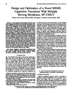
microchips. MEMS have applications in various fields such as Automotive, Medical, Communication, Defense and so on. Pressure sensors are playing a vital role today in modern industries. MEMS pressure sensor is being widely adopted in different applications for its high-performance, low cost and small size. MEMS pressure sensor is one of the very first MEMS components that appeared in the micro system world. MEMS pressure sensor for consumer applications especially for smart phones and tablets, follow the model of accelerometers and gyroscopes. Since pressure sensors have diverse applications, it has certain specifications that are adopted to make them work optimally in a given environment. MEMS capacitive pressure sensors have many advantages over other types of sensors such as low noise, high sensitivity to temperature, low power consumption compared to other sensors and used in high power applications. This is the motivation for proposed work, to use capacitive pressure sensor. Micro machined capacitive pressure sensors typically use two elastic diaphragms with a sealed cavity in between. These diaphragms form parallel plates required for capacitive mechanism. Lower plate is fixed and upper plate acts as movable plate. The work considers clamped diaphragms. Simple capacitive pressure sensor model is shown in Fig. 1.
Keywords MEMS pressure sensor array, Polysilicon, Linearity, Switching, COMSOL, Simulink, Diaphragm thickness.
1. INTRODUCTION Micro-electro mechanical systems (MEMS) are a technology used to create tiny integrated devices, which are fabricated using integrated circuit (IC) batch processing techniques. These systems have the ability to sense, control and actuate on the micro scale, and generate effects on the macro scale. In the most general form, MEMS consists of mechanical micro structures, micro sensors, micro actuators and micro electronics, all integrated. MEMS have several distinct advantages as a manufacturing technology. In first place the interdisciplinary nature of MEMS technology and its micromachining techniques, as well as its diversity of applications has resulted in its use in large domain of application, which were actually untouched. Secondly, MEMS with its batch fabrication techniques enables components and devices to be manufactured with increased performance and reliability, combined with the obvious advantages of reduced physical size, volume, weight and cost. Thirdly, MEMS provides the basis for the manufacture of products that cannot be made by other methods. These factors make MEMS as pervasive technology as integrated circuit
Fig. 1 Capacitive Pressure Sensor The applied pressure is directly proportional to the capacitance between the diaphragms. The capacitive value is calculated using the below equation.
c
o r A d
39
International Journal of Computer Applications (0975 – 8887) Volume 163 – No 6, April 2017 Where C=Capacitance value of the system, 0 = Relative permittivity of free space = 8.854*(10-12) F/m, r = Relative permittivity of free dielectric medium, A = effective surface area and d = separation distance between the membrane. This work aims at designing an efficient MEMS capacitive pressure sensor array for broad measurement range and to read out output within better linearity using conditional switching mechanism, possible with COMSOL and MATLAB Simulink model. This makes pressure sensor array a universal pressure sensor. Rest of the paper is organized as following. In section II literature review over designing of MEMS capacitive pressure sensor array is done. In section III the proposed work is explained briefly In section IV simulation of proposed work is explained. In sections V and VI describe results and conclusion at last.
2. LITERATURE REVIEW Paper [1] provides an overview including developments, challenges with respect to design, modeling, simulation and analysis of MEMS pressure sensors. The paper provides a review on various types of capacitive pressure sensor principles, design, modelling, parameters and simulation. In paper [2], two MEMS capacitive pressure sensors with varying geometries are analyzed in FEM based Multi-physics simulation platform. The geometries are very common having parallel plates with spring loaded. In first case the shape of the parallel plates are circular and in second case it is square. During modeling of these two different shaped sensors, the area of parallel plates in both cases is set equal. Electromechanical analysis has been performed and observed that these types of pressure sensors can withstand a wide range of absolute pressure from kPa to several MPa. This sensor targets a absolute pressure measurement for pulse rate measurement. Paper [3], describes the design of MEMS based capacitive pressure sensor using COMSOL/Multi-physics. It provides detailed visualization of distributions of stresses and displacements. Deflection, Eigen frequency and stress of the capacitive pressure sensor are computed. The capacitance measurement is simulated for a capacitive pressure sensor for a capacitance of about 2.12e-14F. In paper [4], the effect of variations in shape and membrane thickness in capacitive pressure sensors is pictorized. Specifically, square, rectangular and circular shapes are considered with three different membrane thicknesses. Capacitive changes and membrane deformations with respect to pressure variation were computed using the IntelliSuite simulation software, and the sensitivity of the sensor was assessed. Square-shaped pressure sensor with least membrane thickness was found to be more sensitive than the circular and rectangular shaped sensors, with the rectangular one showing the least sensitivity. In paper [5], various factors which play a critical role in the performance of a MEMS pressure sensor are discussed. The design of the diaphragm is vital for the efficiency of the sensor. The dimensions of the diaphragm like length, radius, thickness and shape are taken into consideration and the effects of variations in pressure on the geometry of the sensing element are discussed using the Weka data mining tool. In paper [6], for the first time, the modeling of capacitance and sensitivity for MEMS capacitive pressure sensor with clamped square diaphragm is presented. In capacitive sensor the sensitivity is proportional to deflection and capacitance changes with pressure. Therefore, first the diaphragm displacement, capacitance and sensitivity of sensor with square diaphragm have been modeled and then simulated using FEM. It can be seen that the analytical results agree
with simulation. The results also show that the high sensitivity can be achieved by decreasing the diaphragm thickness and increasing its size. In paper [7], novel Liquid Crystal Polymer (LCP) based capacitive pressure sensors are fabricated using printed circuit processing techniques. LCP exhibits good dimensional stability, material flexibility, high chemical resistance, and extremely low moisture absorption, which makes it suitable for MEMS applications. The pressure sensor comprises of a cylindrical cavity formed by a sandwich of LCP substrate, LCP spacer layer with circular holes and LCP top layer. The bottom electrode and the top electrode of the capacitive pressure sensor are defined on the top surface of the LCP substrate and the bottom surface of the top LCP layer, respectively. A typical pressure sensor with a diaphragm diameter of 3.2 mm provides a total capacitance change of 0.7627 pF for an applied pressure in the range of 0170 kPa. In paper [8], the design and simulation of capacitive and piezo-resistive MEMS pressure sensors for pressure measurement are described. Performance measurement parameters like sensitivity and deflection of both the sensors are compared through simulated results. The comparison supports to know the suitability of sensors for various applications. It also helps to know the change in behavior and performance of a sensor due to change in geometrical parameters of the sensors such as L/h ratio, thickness etc. In paper [9], the design simulation and characterization of a blood pressure sensor for healthcare and biomedical applications is presented. Vital sign measurement and assessment are important components of the review of systems in a physical therapy examination for individuals with and without documented cardiopulmonary disease. The measurement of blood pressure based on the blood flow gives the therapist information regarding the patient‟s baseline cardiovascular status, response to exercise/activity, and guides exercise prescription. Accurate measurement of blood pressure is critical for making appropriate clinical decisions especially if physical therapists or doctors wish to play an important role as primary health care providers. This paper presents a stimulated structure used for measuring accurate pressure of blood flow through a vein or an artery using basic known technology of microelectromechanical (MEMS) systems along with the simulation of design on CATIAV5. The literature survey reveals that, Capacitive pressure sensor received special attention due to several advantages over Piezo-resistive pressure sensor and others. Capacitive pressure sensor with square diaphragm is more sensitive than circular and rectangular diaphragms. For a particular pressure, the deflection as well as the change in capacitance of Polysilicon type diaphragm is greater compared to the silicon and SiC type diaphragm. Diaphragm deflection and change in capacitance are inversely related to diaphragm thickness. This motivates in designing an array of square diaphragm based capacitive pressure sensor of different diaphragm thickness on a single silicon substrate with Polysilicon as the diaphragm material.
3. METHODOLOGY The proposed model consists of an array of capacitive pressure sensors of different diaphragm thickness on a single silicon base substrate. The model consists of 4 capacitive pressure sensors with diaphragm thickness of 1.5µm, 2µm, 2.5µm and 3µm. Fig. 2 shows the model of MEMS capacitive pressure sensor array. Each block represents one capacitive pressure sensor with different measuring range. The diaphragm of each block is made up of Polysilicon with air
40
International Journal of Computer Applications (0975 – 8887) Volume 163 – No 6, April 2017 sealed cavity between them. In the proposed model the dimensions of each block is as given below with air sealed cavity of 3μm.
Pressure is applied on each of the block separately in terms of MPa. The applied pressure is increased in steps of 0.25MPa till the top diaphragm displaces to one third of the distance between top and bottom plate of each sensor. The simulated capacitance value with respect to applied pressure is noted and compared with analytically calculated values using the formula given below
C C0 C0
Where, C- Capacitance for applied pressure P, C0Capacitance at zero pressure, P- Pressure applied, l- Length of diaphragm, d- Distance between top and bottom diaphragms, h- Thickness of diaphragm. The graphical comparison of simulated and analytically calculated capacitance values is carried through MATLAB, which is as shown in Fig. 3. It is found that simulated (blue) and analytical values (red) are nearly equal. The linearity range is obtained by plotting simulated capacitance values with respect to applied pressure for each sensor and linear fitting is done using Data fit software. The linearity range of sensor1 is 0-6MPa i.e capacitance value vary linearly with respect to applied pressure in this range. This is clearly pictorized in Fig. 4. In the same way, linearity range of sensor2, sensor3 and sensor4 is 3.25-14.25MPa, 6.25-22.25MPa and 9-33.25MPa respectively. This is as shown in Fig. 5-7. On obtaining the linearity ranges of all the four sensors the pressure input is given to each of the sensor in the array model using combinational mechanism which is available in COMSOL software. It helps in switching from one sensor to other when applied pressure increases above certain linearity range. This makes the lower linearity range sensors stable in the array. Combinational input is as shown in below fig.. Add all the parameters globally and put specified combinations as shown in fig. 8.
Fig. 2 The block diagram of Pressure Sensor Array a. Sensor1 Height of the diaphragm- 1.5μm, Width of the diaphragm60μm, Depth of the diaphragm- 60μm b. Sensor2 Height of the diaphragm- 2μm, Width of the diaphragm60μm, Depth of the diaphragm- 60μm c. Sensor3 Height of the diaphragm- 2.5μm, Width of the diaphragm60μm, Depth of the diaphragm- 60μm d. Sensor4 Height of the diaphragm- 3μm, Width of the diaphragm60μm, Depth of the diaphragm- 60μm -14
1.2
-14
Sensor1
x 10
1.35
1.16 1.14 1.12 1.1
1.2 1.15 1.1
1.06
1.05
0
1
2
-14
3 Pressure applied
4
5
6
2
4
6
-14
Sensor3
x 10
0
6
x 10
1.6
1.35
8 10 Pressure applied
12
14
16
18 6
x 10
Sensor4
x 10
1.5 Change in capacitance
Change in capacitance
1.25
1.08
1.3 1.25 1.2 1.15
1.4 1.3 1.2 1.1
1.1 1.05
Sensor2
x 10
1.3 Change in capacitance
Change in capacitance
1.18
1.4
12.5* P * l 2025* d * h
0
0.5
1
1.5 Pressure applied
2
2.5
3 7
x 10
1
0
0.5
1
1.5
2 2.5 Pressure applied
3
3.5
4
4.5 7
x 10
Fig. 3 Comparison of simulated and analytical capacitance
41
International Journal of Computer Applications (0975 – 8887) Volume 163 – No 6, April 2017
B Linear Fit of Data1_B
B Linear Fit of Data4_B
1.20E-014
1.20E-014
1.16E-014
Change in Capacitance
Change in Capacitance
1.18E-014
1.14E-014
1.12E-014
1.10E-014
1.14E-014
1.08E-014
1.08E-014 1.06E-014 0
1000000
2000000
3000000
4000000
5000000
6000000
0
Applied Pressure
7000000
Fig. 4 Change in Capacitance Vs Applied Pressure of sensor1 sensor2
Fig. 5 Change in Capacitance Vs Applied Pressure of
B Linear Fit of Data3_B
B Linear Fit of Data4_B
1.20E-014
1.19E-014
Change in Capacitance
Change in Capacitance
14000000
Applied Pressure
1.14E-014
1.12E-014
1.08E-014
0
10000000
20000000
0.00E+000
Applied Pressure
2.00E+007
4.00E+007
Applied Pressure
Fig. 6 Change in Capacitance Vs Applied Pressure of sensor3
Fig. 7 Change in Capacitance Vs Applied Pressure of sensor4
Add all the parameters globally and put specified combinations shown in fig. 8.
Fig. 8 Combinational input for switching mechanism
42
International Journal of Computer Applications (0975 – 8887) Volume 163 – No 6, April 2017 The boundary load is applied on sensor 1, 2, 3 and 4 in thier linearity range with the help of combinational mechanism as shown in Fig. 9. For example, if pressure is 4.25MPa then it is applied on sensor1 and sensor2 and if the pressure is
33.25MPa then it just switches to sensor4. This is how switching takes place and it is clearly picturised in Fig. 10 and Fig. 11.
Fig. 9 Boundary load applied to sensor2 within its linearity range
Fig. 10 Applied Pressure of 4.25MPa on sensor1 In this way, switching mechanism takes place in the proposed array model. The obtained capacitance value for an unknown applied pressure is used in Simulink model containing look-up table to get the pressure applied as shown in Fig. 12. Similar look-up tables are put for sensor 2, 3, and 4 which contains pre-data base of capacitance values for a definite pressure applied. This is how pressure measurement is done for a wide range.
Fig. 11 Applied Pressure of 33.25MPa on sensor4
4. RESULTS AND DISCUSSION The result consists of 4 stages, in first stage the pressure with index value 1-25 is applied on sensor1, in second stage the pressure with index value 26-70 is applied on sensor2, in third stage the pressure with index value 71-135 is applied on sensor3 and in the fourth stage the pressure with index value 136-233 is applied on sensor4. If for example index value is 28 then the pressure is applied on sensor2 and the Displacement of sensor2 is as shown in Fig. 13.
43
International Journal of Computer Applications (0975 – 8887) Volume 163 – No 6, April 2017
Fig. 12 Look-Up table of sensor1
Fig. 13 Diaphragm displacement of sensor2 Capacitance across sensor2 is obtained by selecting index value as 28 in capacitance 3D plot. This is as shown in Fig. 14. Capacitance across sensor2 is found to be 1.09055E-14 farad. This is to be put in Simulink model as an input to obtain the applied pressure value, where it checks the look-up table.
As number of array elements i.e sensor elements increases to „n‟ number, the calculation of pressure applied for the capacitance obtained becomes complex in an array.
44
International Journal of Computer Applications (0975 – 8887) Volume 163 – No 6, April 2017
Fig. 14 Capacitance of each sensor in an array Hence a pre-data base containing capacitance values with respect to applied pressure of each sensor element is to be maintained, this is shown in Fig. 12. The Simulink model containing look-up table is shown in Fig. 15 where constant block represents capacitance value given as input to all 4 sensor elements look-up table, the applied pressure is found to be 3.75MPa in Display scope.
Fig. 15 Simulink model with look-up table to find applied pressure
5. CONCLUSION AND FUTURE SCOPE
6. REFERENCES
The novel design of MEMS capacitive pressure sensor array helps in measuring pressure over a large range of about 033.25MPa with the help of combinational switching mechanism possible with COMSOL Multi-physics. This makes the design a universal and can be used for variety of applications. The measuring range can be varied by varying diaphragm thickness of each sensor in an array. But practically intelligent circuitry is to be used for switching operation in the array model. In future, number of array elements can be increased to „n‟ number with varying dimensions of diaphragm to increase pressure measurement over a long range according to the requirement in application.
[1] Kirankumar B. Balavalad, B. G. Sheeparamatti, “A Critical Review on MEMS Capacitive Pressure Sensors”, Sensors & Transducers journal, IFSA publication, ISSN: 2306-8515, e-ISSN 1726-5479 Volume 187, Issue 4, pp120-128, April 2015. [2] Priya Singha Roy “A Simulation Based Geometrical Analysis of MEMS Capacitive Pressure Sensors for High Absolute Pressure Measurement”, Dept. of Applied Electronics and Instrumentation Engineering, IESA 2014. [3] Priya Singha Roy, Madhurima Chattopadhyay, “Simulation of MEMS Based Capacitive Pressure Sensor
45
International Journal of Computer Applications (0975 – 8887) Volume 163 – No 6, April 2017 Using Comsol Multiphysics”, Kurukshetra Institute of Technology & Management, Kurukshetra. [4] Arash Sabet, Xavier J. Avula, “Sensitivity to Shape and Membrane Thickness Variations in Capacitive Pressure Sensors”, Department of Mechanical and Aerospace Engineering Washington University in St. Louis, Campus Box 1185, Jolley Hall 305. [5] K. Y. Madhavi, M Krishna, “Diaphragm Design for MEMS Pressure Sensors using a Data Mining Tool”, World Congress on Engineering 2011 Vol II July 6 - 8, 2011. [6] B. A. Ganji, M. Shams Nateri, “Modeling of Capacitance and Sensitivity of a MEMS Pressure Sensor with Clamped Square Diaphragm”, Department of Electrical & Computer Engineering, Babol University of Technology, Babol, Iran. [7] Jithendra N Palasagaram and Ramesh Ramadoss, “MEMS Capacitive Pressure Sensor Array fabricated Using Printed Circuit Processing Techniques”, Department of Electrical and Computer Engineering, Auburn University.
IJCATM : www.ijcaonline.org
[8] M.Z. Shaikh, Dr. S.F. Kodad, Dr. B.C. Jinaga, “A Comparative Performance Analysis Of Capacitive And Piezoresistive MEMS For Pressure Measurement”, International Journal Of Computer Science And Applications Vol. 1, No. 3, December 2008 ISSN 09741003. [9] Shivam Kohli, Anish Saini, “MEMS BASED PRESSURE SENSOR SIMULATION FOR HEALTHCARE AND BIOMEDICAL APPLICATIONS”, International Journal of Engineering Sciences & Emerging Technologies, Dec. 2013. ISSN: 2231 – 6604. [10] MEMS & NanoTechonology Lab, School of Mechanical Systems Engineering, Chonnam National University, Intelligent Machine Technology, KIMM. [11] http://www.wrh.noaa.gov/slc/projects/wxcalc/formulas/p ressureConversion.pdf [12] Richard De Jongk, "MEMS Pressure Sensor Array for Aeroacoustic Analysis of the Turbulent Boundary Layer", Calvin College, Grand Rapids, MI, USA.
46