Using Comsol Multiphysics for Intraoral Applications. 1Mr.K.Sathesh, 2Dr.N.J.R.Muniraj, 3T.Divya Bharathi, 3S.Priyadarshini,3S.Sharmila. 1Research Scholar ...
ISSN (Online): 2319-8753 ISSN(Print): 2347 - 6710
International Journal of Innovative Research in Science, E ngineering and Technology An ISO 3297: 2007 Certified Organization,
Volume3, Special Issue 4, April 2014
Second National Conference on Trends in A utomotive Parts Systems and Applications (TAPSA-2014)
On 21st& 22nd March, Organized by Sri Krishna College of Engineering & Technology, Kuniamuthur, Coimbatore-641008, Tamilnadu, India
Modeling and Simulation of Capacitive Pressure Sensor Using Comsol Multiphysics for Intraoral Applications 1
Mr.K.Sathesh, 2 Dr.N.J.R.Muniraj, 3T.Divya Bharathi, 3S.Priyadarshini, 3 S.Sharmila 1
Research Scholar, Anna University, Chennai, India
2
Principal,Tejaa Shakthi Institute of Technology for Women, Coimbatore, India
3
Department of Electronics and Communication Engineering, Anna University, Tejaa Shakthi Institute of Technology for Women, Coimbatore, India.
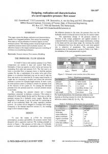
ABSTRACT: Tooth grinding is a contentiousphenomenon. Both its definition and the diagnostic procedure contribute to the fact that the literature about the set of causes of this disorder is difficult to explicate. Further, factors like smoking, alcohol, drugs, diseases and trauma may cause tooth grinding. Psychological factors like stress and personality are frequently allude to bruxism as well. However, research to these factors comes to vacillating results and needs further attention. Taken all evidence together, bruxism appears to be mainly controlled. In order to study teeth grinding behaviour and other oral conditions requires the ability to accurately measure the pressure on the teeth. So design of pressure sensor is being proposed. This pressure sensor measures the grinding force applied on teeth. So to place a sensor in the mouth requires small size devices with powering and measurement techniques that do not hinder the normal life of the patient. To meet these requirements, a MEMS based Capacitive sensor is being designed for its biocompatibility and zero power consumption. KEYWORDS- Bruxism, Pressure Sensor, Force, Biocompatibility, Zero power consumption. I. INTRODUCTION Tooth grinding is an activity which results in tooth wreckage, breakage of dental restoration or rehabilitation, intensification of temporomandibular disorders or initiation of temporal tension headache and grinding sounds. The movement disorder characterized by grinding and clenching of teeth for non-functional prospect is Bruxism. It is an oral parafunctional activity that are non-functional oromandibular or lingual motion. Studying teeth grinding activity and other oral conditions requires the potential to accurately measure the pressure on the teeth. Pressure is force per unit area applied in a direction perpendicular to the surface of an object. Thus a Capacitive pressure sensor is used.
Fig.1 Positioning of the Sensor in the Mouth
Copyright to IJIRSET
www.ijirset.com
151
ISSN (Online): 2319-8753 ISSN(Print): 2347 - 6710
International Journal of Innovative Research in Science, E ngineering and Technology An ISO 3297: 2007 Certified Organization,
Volume3, Special Issue 4, April 2014
Second National Conference on Trends in A utomotive Parts Systems and Applications (TAPSA-2014)
On 21st& 22nd March, Organized by Sri Krishna College of Engineering & Technology, Kuniamuthur, Coimbatore-641008, Tamilnadu, India
II. SYSTEM MODEL A. Capacitance A Capacitor is a device that can stock charge. A capacitor is a device that dwells two conductive plates serrated by a small distance, with the distance and surface area of the plates disporting a part in the total capacitance of the capacitor. A capacitor is charged by fleeting current through it. One plate of the capacitor will collect positive charge and the other negative charge. As the charge frames up on each plate, a voltage potential figures up between the plates. This voltage potential crosswise the capacitor will endure to frame until it meets the voltage source. The amount of charge dwelled in a capacitor is resolved by the equation Q=CV Where Q is the stocked charge in coulombs, C is the capacitance of the device in farads and V is the voltage across the device. B. Capacitive Pressure Sensor Capacitive pressure (C-P) plate sensors quote changes in pressure by the deflection of a conducting diaphragm due to applied pressure. Parallel plate C-P sensors mostly have a field between the two electrodes, and the deflection in the diaphragm crops a quadratic modification in capacitance. C-P sensors deprived with a diaphragm that contacts a dielectric coated ground plane customarily have a nonlinear response at lower pressures and a larger, more linear response at higher pressure ranges with consideration to the full range of the sensor. An initial pressure is essential to bring the conducting plane in connection with the reference ground plane, and the residual stress in the diaphragm adds a substantial resistance to deformation correlated to the driving force builds by the applied pressure. This residual stress shortens the sensitivity at low pressures and produces a nonlinear signal. Capacitive sensing mechanisms can easily be engaged to realize pressure sensors, despite the fact that this mechanism is intrinsically non-linear (because capacitance is inversely proportional to gap width). Since the membranes engaged are consistently clamped at all edges, the capacitance of such membranestructures is not given easily by the parallel-plate capacitor equation, but it can be used as a crude starting point, C= Є x A/D This gives a ΔC in terms of change in gap width, Ώ d, of, ΔC = Є x A x Ώ d /d. C. Capacitance in Bio-Medical Applications Micro Electro Mechanical Systems is a present technology that can miniaturize mechanical and electro mechanical elements that are made using the approach of microfabrication. The range of these devices can vary from one micron to several millimeters. Similarly, these devices can vary from relatively uncomplicated structures that have no moving elements to immensely complex electromechanical systems with multiple moving elements under the control of integrated microelectronics. Recently MEMS Capacitive Pressure Sensor gains more advantage over micromachinedpiezoresistive pressure sensor due to high sensitivity, low power consumption, free from temperature effects, IC compatibility, etc,. The spectrum of capacitive pressure sensor application is increasing, hence it is essential to review the path of technological development and further prospective of micromachined capacitive pressure sensor. The sensitivity curve of piezoresistive is steeper than that of capacitive pressuresensor piezoresistive pressure sensor sensitivity changes up to 180mmHg whereas capacitive pressure sensor sensitivity changes up to 335mmHg. From this discussion it can be concluded that the sensitivity of capacitive pressure sensor is more than that of piezoresistive pressure sensor the smaller value of thickness has more deflection. Capacitive pressure sensor has larger pressure dependency due to which there is fast response in the deflection for minimum thickness than the piezoresistance sensor. Capacitive MEMS are even more suitable for Bio medical applications especially pressure measurement. III. DESIGN OF SENSORS A. Geometry The fixed plate is kept static. The movable plate is placed above the fixed plate and the gap between fixed and the movable plate is 1µm. The radius of the fixed and movable plate is kept same in order to sense comfortably. Above Copyright to IJIRSET
www.ijirset.com
152
ISSN (Online): 2319-8753 ISSN(Print): 2347 - 6710
International Journal of Innovative Research in Science, E ngineering and Technology An ISO 3297: 2007 Certified Organization,
Volume3, Special Issue 4, April 2014
Second National Conference on Trends in A utomotive Parts Systems and Applications (TAPSA-2014)
On 21st& 22nd March, Organized by Sri Krishna College of Engineering & Technology, Kuniamuthur, Coimbatore-641008, Tamilnadu, India
the movable plate coupling is placed which is used to couple movable plate and diaphragm. The isolator which is kept below diaphragm and so the radius of the coupling and isolator are kept small than diaphragm radius to increase sensitivity. The thickness of each cylinder is maintained as 1µm to achieve maximum sensitivity. All the five plates are kept circular to have high dynamic range whereas structures like square and rectangle has lower dynamic range because of high stress points and corners.
Fig.2 Geometry of the Capacitive Pressure sensor using COMSOL Multiphysics. B. Operation Normally a capacitive pressure sensor has a diaphragm for sensing the pressure. By increasing the diaphragm size, reducing the diaphragm thickness and decreasing sensing gap we can achieve high sensitivity of the sensor. Pressure is applied on the upper layer of the diaphragm and the relative change in the deformation in the structure of the diaphragm can be sensed by the movable plate via coupling plate. The change in pressure is the measure of reduction in gap between the two plates (fixed and movable). Geometry of the capacitor can be changed to adjust dynamic range and sensitivity. The principle of the design is that pressure deflects the diaphragm until the elastic reaction force of the diaphragm balances it. IV. RESULT AND DISCUSSION The capacitive pressure sensor made up of Poly-Si material is capable of sensing pressure by deforming from its original structure. The pressure sensor is given Young’s modulus E= 160Gpa and Poisson ratio v=0.22 then the deformation for all the given parametric values is shown in fig. This sensor increases understanding of the large pressure dependency due to which there is fast response in the deflection for minimum thickness as analysed in the graph( shown in Fig.4).
Copyright to IJIRSET
www.ijirset.com
153
ISSN (Online): 2319-8753 ISSN(Print): 2347 - 6710
International Journal of Innovative Research in Science, E ngineering and Technology An ISO 3297: 2007 Certified Organization,
Volume3, Special Issue 4, April 2014
Second National Conference on Trends in A utomotive Parts Systems and Applications (TAPSA-2014)
On 21st& 22nd March, Organized by Sri Krishna College of Engineering & Technology, Kuniamuthur, Coimbatore-641008, Tamilnadu, India
Fig.3 Ideal outcome of Force versus Maximum deflection for the pressure in the scale of 5
Fig.4 Rational outcome of Force versus Maximum deflection for the pressure in the scale of 5 It is found from the result that the Force versus Maximum deflection of Diaphragm that the smaller value of thickness has more deflection. If the applied pressure is maximum then the deflection in the moving plate will be maximum. V. CONCLUSION Thus MEMS basedCapacitive pressure sensor with very low temperature dependence, miniature size, low power consumption and with suitable dynamic pressure range was designed and simulated. From the result it is clear that the amount of deflection with respect to material, diaphragm thickness, sensing gap, can influence applied pressure. Thus a capacitive pressure sensor with appropriate influencing factors is made. VI. FUTURE WORK For healthy monitor of pressure the capacitance should be added to the resonance tank so that the change in resonance frequency will make possible to measure the pressure. And also include energizing circuit and an adaptive
Copyright to IJIRSET
www.ijirset.com
154
ISSN (Online): 2319-8753 ISSN(Print): 2347 - 6710
International Journal of Innovative Research in Science, E ngineering and Technology An ISO 3297: 2007 Certified Organization,
Volume3, Special Issue 4, April 2014
Second National Conference on Trends in A utomotive Parts Systems and Applications (TAPSA-2014)
On 21st& 22nd March, Organized by Sri Krishna College of Engineering & Technology, Kuniamuthur, Coimbatore-641008, Tamilnadu, India
filter to adjust the energizing frequency to new resonance frequencies to in order to improve reliability and freedom in design. REFERENCES [1]. AbhijeetV.Chavan, Kensall D., “A Monolithic Fully-Integrated Vacuum-Sealed CMOS Pressure Sensor”, IEEE Transactions onElectron Devices, Vol. 49, No. 1, pp. 164-170, January 2002. [2]. C.Hierold, B.Clasbrummel. “Low power integrated pressure sensor system for medical applications,” Sensors and Actuators (Part A) Physical, no. 73, 1999, pp. 68-67. [3]. Guchuan Zhu, LahcenSaydy, MehranHosseini, Jean-François Chianetta, and Yves-Alain Peter, “A Robustness Approach for Handling Modeling Errors in Parallel-Plate Electrostatic MEMS Control”, Journal of Microelectromechanical Systems, vol. 17 , Issue: 6 pp. 1302 – 1314, Dec. 2008. [4]. Yong s lee, kensall D. wise, “A batch fabricated silicon capacitive pressure transducer with low temperature sensitivity”, IEEE transactions on Electron Devices, Vol, 29, No.1, pp. 42-49, January 1982. [5]. Y. Zhang, S. Massoud-Ansari, G. Meng, W. Kim, and N. Najafi, "A Ultra-Sensitive, High-Vacuum Absolute Capacitive Pressure Sensor," TechnicalDigest of the 14th IEEE International Conf. on MicroElectro Mechanical Systems (MEMS 2001), pp. 166-169, Interlaken, Switzerland, Jan. 21-25, 2001. [6]. Y.Hezarjaribi, M.N.Hamidon, S.H.Keshmiri, A.R.Bahadorimehr, ‘Capacitive pressure sensors based on MEMS, operating in harsh environments’, ICSE 2008 proc 2008, Johor, Malaysia. [7]. Albert Lozano-Nieto, "Educating students in the new wireless technologies: Educational experiences in RFID systems," the Technology Interface Journal, 10, No. 3 Spring (2010). [8]. Vladimir Kutis, Jaroslav Dzuba, JurajPaulech, Justin murin, JurajHrabovsky, TiborLalinsky, ‘Piezoelectric analysis of MEMS pressure sensor’. [9]. Youbok Lee, "Antenna Circuit Design for RFID Applications," AN710, Microchip Technology Inc., (2003)International Journal Of Computer Science And Applications Vol. 1, No. 3, December 2008. [10]. K.V.Seshagiri Rao, V.Nikitin, ‘Antenna design for UHF RFID tags: A review and a practical application’, IEEE transactions on antennas and propagation, vol.53, no.12, dec 2005. [11]. T.T.T.Dao, G.J.Lavigne, ‘Oral splints: The crutches for temporomandibular disorders and bruxism’. [12]. Sleep bruxism: Therapeutic possibilities based in evidences, Machado, Eduardo; Machado, Patricia; Cunali, Paulo Afonso; Dal Fabbro, Cibele (2011), Dental Press Journal of Orthodontics16 (2): 58–64. [13]. NestoriucYuonne; Martin, A; Rief, W; Andrasik, F (September 2008). "Biofeedback treatment for headache disorders: a comprehensive efficacy review", Applied psychophysiology and biofeedback33 (3): 125–40. doi:10.1007/s10484-008-9060-3. PMID 18726688. [14]. Nestoric Y, Rief, Winfried, Martin, Alexandra, ‘Meta-analysis of biofeedback for tension-type headache:efficacy, specificity and treatment moderators’, journal of consulting and clinical psychology, volume 76(3), june 2008, p 379-396. [15]. Erik peper, Richard Harvey, Naoki Takabayashi, ‘Biofeedback an evidence based approach in clinical practise’, Japanese Journal of Biofeedback Research, 36(1), 3-10. [16]. J.O. Dennis, M.S.B. Mat Sihat,, A. Yousif Ahmed and Farooq Ahmad “ Piezoresistive Pressure Sensor Design, Simulation and Modification using Coventor Ware Software” Journal of Applied Sciences, 8, pp. 1426-1430, (2011).
Copyright to IJIRSET
www.ijirset.com
155