I2c Bridge Protocol by using System Verilog and OVM. Keywords: ..... Mastering
the I²C Bus; Vincent Himpe; 248 pages; 2011; ISBN 978-0-905705-98-9. [14].
IOSR Journal of Electronics and Communication Engineering (IOSR-JECE) e-ISSN: 2278-2834,p- ISSN: 2278-8735.Volume 8, Issue 2 (Nov. - Dec. 2013), PP 27-31 www.iosrjournals.org
Design and Verification of USB-I2C Bridge Protocol by OVM K Surya Narayana Reddy*, K Jansi Lakshmi
**
Asst .Professor in Dept of ECE ,Annamacharya Institute of Technology and Sciences, Tirupati-517520, Chittoor Dist., INDIA, Asst .Professor in Dept of ECE ,Annamacharya Institute of Technology and Sciences, Tirupati-517520, Chittoor Dist., INDIA,
Abstract: The challenge of the verifying a large design is growing exponentially. There is a need to define new methods that makes functional verification easy. Several strategies in the recent years have been proposed to achieve good functional verification with less effort. Recent advancement towards this goal is methodologies. The methodology defines a skeleton over which one can add flesh and skin to their requirements to achieve functional verification. Open verification methodology (OVM) is one such efficient methodology and best thing about it is, it is free. This OVM is built on system verilog and used effectively to achieve maintainability, reusability, speed of verification etc. This project is aimed at building a reusable test bench for verifying UsbI2c Bridge Protocol by using System Verilog and OVM Keywords: verification; methodology; Usb-I2c Bridge Protocol; System Verilog;
I.
Introduction
Verification is not a test bench, nor is it a series of test benches. Verification is a process used to demonstrate that the intent of a design is preserved in its implementation. Importance of verification Today, in the era of multi-million gate ASICs and FPGAs, reusable intellectual property (IP), and system-on-a-chip (SoC) designs, verification consumes about 70% of the design effort. Design teams, properly Given the amount of effort demanded by verification, the shortage of qualified hardware design and verification engineers, and the quantity of code that must be produced, it is no surprise that, in all projects, verification rests squarely in the critical path. The fact that verification is often considered after the design has been completed, when the schedule has already been ruined, compounds the problem. It is also the reason verification is the target of the most recent tools and methodologies. These tools and methodologies attempt to reduce the overall verification time by enabling parallelism of effort, higher abstraction levels and automation. If efforts can be parallelized, additional resources can be applied effectively to reduce the total verification time. For example, digging a hole in the ground can be Parallelized by providing more workers armed with shovels. To parallelize the verification effort, it is necessary to be able to write—and debug—test benches in parallel with each other as well as in parallel with the implementation of the design. Functional verification approaches Functional verification can be accomplished using three complementary approaches: black-box, whitebox and grey-box. a. Black box verification With a black-box approach, functional verification is performed without any knowledge of the actual implementation of a design. All verification is accomplished through the available interfaces, without direct access to the internal state of the design, without knowledge of its structure and implementation. This method suffers from an obvious lack of visibility and controllability. It is often difficult to set up an interesting state combination or to isolate some functionality. The advantage of black-box verification is that it does not depend on any specific implementation. Whether the design is implemented in a single ASIC, RTL code, transactionlevel model, gates, multiple FPGAs, a circuit board or entirely in software, is irrelevant.
b. White box verification
As the name suggests, a white-box approach has full visibility and controllability of the internal structure and implementation of the design being verified. This method has the advantage of being able to set up an interesting combination of states and inputs quickly, or to isolate a particular function. It can then easily observe the results as the verification progresses and immediately report any discrepancies from the expected behavior. www.iosrjournals.org
27 | Page
Design And Verification Of USB-I2C Bridge Protocol By OVM c. Gray box verification Grey-box verification is a compromise between the aloofness of black-box verification and the dependence on the implementation of white-box verification. The former may not fully exercise all parts of a design, while the latter is not portable.
Testing versus verification Testing is often confused with verification. The purpose of the former is to verify that the design was manufactured correctly. The purpose of the latter is to ensure that a design meets its functional intent. During testing; the finished silicon is reconciled with the net list that was submitted for manufacturing. Testing is accomplished through test vectors. The objective of these test vectors is not to exercise functions. It is to exercise physical locations in the design to ensure that they can go from 0 to 1 and from 1 to 0 and that the change can be observed. The ratio of physical locations tested to the total number of such locations is called test coverage. The test vectors are usually automatically generated to maximize coverage while minimizing vectors through a process called automatic test pattern generation (ATPG).
II. Verification Methodology Methodology is a systematic way of doing things with a rich set of standard rules and guidelines. Methodology provides the necessary infrastructure to build a robust, reliable and complete Verification environment. Methodology shrinks verification efforts with its predefined libraries. It will make your life easier down the road by preventing you from making mistakes or poor decisions whose outcome may not be obvious at the time you made them. It also helps make sure that whatever you do will mesh nicely with what others do (re-usability).Methodology is basically set of base class library which we can use to build our test benches. Building the testbench environment using Methodologies have following advantages Common test bench structure and run flow. Reusability. Time required to build any test bench is very less. Avoids poor coding practices Debugging simplicity Layered Test bench Architecture Verification Methodology Types List of verification Methodologies are given below AVM Advanced Verification Methodology (System C & Systemverilog) by Mentor Graphics RVM Reference Verification Methodology (open Vera) by Synopsys OVM Open verification Methodology (systemverilog) by Mentor Graphics VMM Verification Methodology Manual (systemverilog) by Synopsys
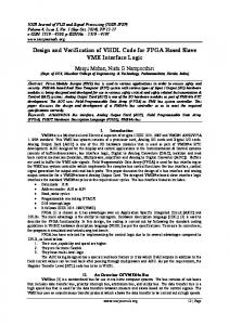
Figure 2-1 OVM Environment OVM components The OVM Verification environment consist of OVM components like OVM Transactor OVM Sequencer OVM Driver OVM Monitor OVM Scoreboard
www.iosrjournals.org
28 | Page
Design And Verification Of USB-I2C Bridge Protocol By OVM OVM Transactor : The transactor contains the code to send the transaction to the next test bench level. Here we are creating the basic transaction class alu_item which is extended from OVM base class ovm_sequence_item. A transaction is just a collection of related data items that get passed around the verification environment as a single unit. OVM Sequencer : A sequencer is an advanced stimulus generator that controls the items that are provided to the driver for execution. By default, a sequencer behaves similarly to a simple stimulus generator and returns a random data item upon request from the driver. OVM Driver: A driver is an active entity that emulates logic that drives the DUT. A typical driver repeatedly receives a data item and drives it to the DUT by sampling and driving the DUT signals. OVM Monitor: A monitor is a passive entity that samples DUT signals but does not drive them. Monitors collect coverage information and perform checking. Even though reusable drivers and sequencers drive bus traffic, they are not used for coverage and checking. OVM Scoreboard: A crucial element of a self-checking environment is the scoreboard. Typically, a scoreboard verifies the proper operation of your design at a functional level. The responsibility of a scoreboard varies greatly depending on the implementation. Making the OVC Reusable: There are times when you as the developer know the context in which the OVC you are developing will be used. In such cases you should take care to separate the requirements of the OVC’s protocol from those of the project. It is strongly recommended that you use only the interface-protocol documentation in developing the OVC. Later, you can consult your project’s documentation to see if there are some generic features which might be useful to implement. For example, you should be able to configure slave devices to reside at various locations within an address space. As another example, if within a protocol frame a few bits are defined as reserved, they should stay reserved within the OVC. The verification logic that understands how a specific implementation uses these bits should be defined outside the global generic code. As a developer, it is critical to identify these generic parameters and document them for the environment users.
III.
Testbench Architecture for USB-I2C Bridge
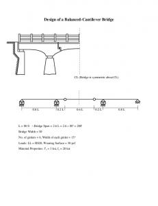
In this paper, we take an example USB-I2C bridge to verify the results by using OVM Interfaces The Interface is a group of I/O signals that connects DUT to the outside world. The interface should be clearly defined for any project so that the components developed will be reused for any project whose interface is same. In USB-I2C Bridge there are two interfaces, one is on USB side and the other is on I2C side. In this section we start defining both the interfaces and all the components should be designed for these interfaces
Figure 3- 1 Top level diagram of DUT USB Interface The USB 2.0 specification says that the USB interface contain four signals, two among them are supply and ground the remaining two signals carry data in differential encoded format. Within these two data lines different voltage levels represent different bus states. The USB-I2C Bridge design claims only digital part has been implemented and not analog parts. So the two data lines should be restricted to strict digital boundaries, but if we do so it is not possible to represent different states of the bus. As a simple solution to this problem the design comes with another signal with which we can represent the states of bus. The original interface signals www.iosrjournals.org
29 | Page
Design And Verification Of USB-I2C Bridge Protocol By OVM are bidirectional but in the design we have two different set of signals for input and output. Since no analog things are designed, power and ground signals can be removed from the interface. Finally two more pins are added for clock and the reset.
Figure 3-3 USB Controller Part of DUT I2C Interface I2C specification defines the interface as two signals one for clock and the other for data. These signals are bidirectional and they are active high signals or they are pulled up. If on either side of the signal wants to drive a zero into the bus, it pulls the signal to low then to drive a one, it releases the signal. To model such a scenario one way is to declare the signals as wands and assign them to 1 so that they are active high, then the signals can be driven by either end with a zero. The second way to do this is to take two different signals connect them as a single wire through a tristate buffer or tristate inverter.
Figure 3-2 I2C Part of the DUT
IV.
Testplan And Results
A collection of all test specifications for a given area the Test Plan contains a high-level overview of what is tested and what is tested by others for the given feature area. The test plan is implemented using ovm test component. Generally the method to write a test case is to define a base test in which all the environment is instantiated and all the common configurations used for all the test cases are written and then articulate test case can extend the base test and then concentrate on implementing a particular test. www.iosrjournals.org
30 | Page
Design And Verification Of USB-I2C Bridge Protocol By OVM Simulation Results The above figures shows the simulation results of test cases applied to the DUT. Figure 4.1shows the response of the device for the control test case at the USB interface. Figure 4.2 shows the master transmitter sending random data to the external slave device.
Figure 4-1Usb Interface signals and some internal signals
Figure 4-2 I2c Interface signals and some internals signals
V.
Conclusion
The result shows that OVM methodology can be used to make reusable test benches successfully. Large part of the test bench is made reusable over multiple projects even though this reusability is limited to the interfaces. A large class of devices that are built on these interfaces can be verified successfully. Once these components are made the amount of time required to build test benches for other projects can be reduced a lot.
References
[1] [2] [3] [4] [5] [6] [7] [8] [9] [10] [11] [12] [13] [14] [15] [16]
J.Bergeron,” what is verification?,” in Writing TestBenches:Functional Verification of HDL Models, 2nd ed.New York:Springerscience,2003, ch1,pp.1-24. Mihaela E.Radhu and Shannon M.Sexton,”Integrating Extensive Functional Verification into digital design Education”,IEEE Trans.Educ.,vol 51,no.3,pp 385-393,Aug.2008. http://testbench.in?TB_07_VERIFICATION_FLOW.html http:/www.doulos.com?knowhow/systemverilog/ovm/tutorial_0/ http:/www.ovmworld.org/white_paper.php http://www.ovmworld.org?whitepapers/OVM_Whitepaper_12-21-07.pdf ovm_open-verification-methodology_cookbook.pdf http://www.testbench.in/OT_02_OVM_TESTBENCH.htm http://www.opencores.org/projects.cgi/web/usb2.0-i2c protocol/overview Wile,J.C.Goss and W.Roesner,”Comprehensive Functional Verification,” MorganKaufmann,ISBN-10:0-12-751803-7,Elsevier 2005. Cadence Designs Systems and Mentor Graphics Inc.,”Open Verification Methodology User Guide” Version 2.0,Sept.2008 avilable from http://www.ovmworld.org M.Mintz, R.Ekendahl,”Hardware verification with SystemVerilog:An object oriented framework”,Spinger ISBN-10:0-387-717382,2007. Mastering the I²C Bus; Vincent Himpe; 248 pages; 2011; ISBN 978-0-905705-98-9. The I2C Bus : From Theory to Practice; Dominique Paret; 314 pages; 1997; ISBN 978-0-471-96268-7. Debugging USB 2.0 for Compliance: It's Not Just a Digital World . Technologies Application Note (1382–3). Agilent.. USB Complete: The Developer's Guide (4th ed.). Lakeview Research. ISBN 978‐1‐931448‐08‐6. 506 pp. *
K.Surya Narayana Reddy receieved B.Tech (ECE) from S.V University,Tirupati,in 2008 and M.Tech (DECS) from JNT University, Anantapur,in 2013. He is currently working as Assistant Professor in Annamacharya Institute of Science and Technology, Tirupati .His research area of interest in VLSI System Design and DIP
www.iosrjournals.org
**
K. Jansi Lakshmi receieved B.Tech (ECE) from JNT University, Hyderabad,in 2010, and M.Tech(VLSI System Design) from JNT University, Anantapur,in 2012.She is currently working as Assistant Professor in Annamacharya Institute of Science and Technology, Tirupati.Her research area of interest in VLSI System Design .
31 | Page