point: integration of DySER into OpenSPARC, a design we call OpenSPlySER. .... of this accelera- tor, the load-slice executes on a general purpose processor,.
Appears in the 18th International Symposium on High Performance Computer Architecture, 2012
Design, Integration and Implementation of the DySER Hardware Accelerator into OpenSPARC Jesse Benson∗ Ryan Cofell∗ Chris Frericks∗ Chen-Han Ho Venkatraman Govindaraju Tony Nowatzki Karthikeyan Sankaralingam Vertical Research Group University of Wisconsin-Madison {vertical}@cs.wisc.edu
Abstract
primitives. However, they all share complexities in both integrating with a general purpose processor and in their utilization, either from the perspective of a compiler/runtime system or programmers themselves. No study has investigated implementation details with regards to how well these techniques port to a commercial design and what practical issues can hamper their integration into a processor.
Accelerators and specialization in various forms are emerging as a way to increase processor performance. Examples include Navigo, Conservation-Cores, BERET, and DySER. While each of these employ different primitives and principles to achieve specialization, they share some common concerns with regards to implementation. Two of these concerns are: how to integrate them with a commercial processor and how to develop their compiler toolchain. This paper undertakes an implementation study of one design point: integration of DySER into OpenSPARC, a design we call OpenSPlySER. We report on our implementation exercise and quantitative results, and conclude with a set of our lessons learned. We demonstrate that DySER delivers on its goal of providing a non-intrusive accelerator design. OpenSPlySERruns on an Virtex-5 FPGA, boots unmodified Linux, and runs most of the SPECINT benchmarks with our compiler. Due to physical design constraints, speedups on full benchmarks are modest for the FPGA prototype. On targeted microbenchmarks, OpenSPlySER delivers up to a 31-fold speedup over the baseline OpenSPARC. We conclude with some lessons learned from this somewhat unique exercise of significantly modifying a commercial processor. To the best of our knowledge, this work is one of the most ambitious extensions of OpenSPARC.
1
In this paper, we report on a study of one particular accelerator design, namely DySER [7], integrated into the OpenSPARC processor pipeline, which we call OpenSPlySER. DySER is a stateless accelerator comprising an array of heterogeneous functional units interconnected with a switched network. A co-designed compiler offloads a portion of the computation onto DySER’s dynamically specialized datapath. This paper reports on the OpenSPlySER system, which consists of a compiler toolchain built using LLVM [12] that produces SPECINT benchmarks and an FPGA mapping of the design that boots Ubuntu 7.10 Linux for SPARC and runs these benchmarks to completion. This paper makes three broad contributions:
Implementation and prototyping description: First, we elucidate the implementation details in prototyping with a commercial processor. We present a design description for integrating DySER into OpenSPARC, spanning issues in ISA design, microarchitecture, RTL implementation, FPGA prototyping, and compiler development. We discuss refinements to the originally proposed DySER design to make it implementable in a prototype, including a discussion on why some of the novel mechanisms from the “original” DySER design proved too difficult to implement (Section 3). We then discuss its interface to the OpenSPARC processor and the changes required in OpenSPARC for DySER integration (Section 4), and the modifications to the compiler toolchain (Section 5) for FPGA prototyping (Section 6).
Introduction
Accelerators and specialization techniques are emerging as an important means to increase processor performance [10, 8, 4, 11, 18, 7, 9]. The primary motivation is to remove the overheads of general purpose processing and thus improve energy and power efficiency. These various specialization efforts, which tightly integrate with a processor’s pipeline, vary significantly in their primary design ∗ First authors Jesse Benson, Ryan Cofell, and Chris Frericks have made equal contributions to this work and are listed alphabetically.
1
Demonstration that DySER is non-intrusive: Second, we demonstrate that the previously proposed DySER architecture can indeed non-intrusively integrate with a commercial processor. An FPGA prototype of OpenSPlySER runs unmodified Ubuntu Linux 7.10, and runs most of the SPECINT benchmarks compiled through our toolchain. This complete software stack was successfully developed in only 10 months with a 5-person team. The details of implementation and the demonstration that integration is possible with a commercial processor is a significant and interesting contribution. Further, the fact that integration was possible without requiring a whole host of additional complexities and enhancements to DySER is a significant positive result adding to the previously proposed DySER work. Lessons learned: Finally, we discuss our lessons learned through the implementation and prototyping process. Our work is subtly different from the many implementation studies in the past [17, 13, 16, 15, 6] and more recent FabScalar [5]. Unlike those previous designs, OpenSPlySER is not a from-scratch design. DySER was proposed with the goal of non-intrusively integrating with existing processors and non-intrusively enabling programmers to utilize it. Thus, it is unique in requiring “easy” integration with an existing processor, and hence must address design and implementation decisions of a different kind. Second, DySER builds upon a large body of work on the compiler side, and our rapid bringup of the software stack provides valuable lessons of interest to the community. Third, unlike those previous efforts, the OpenSPlySER prototype was mapped to a small off-the-shelf FPGA board and not a custom ASIC. We describe some of these challenges and demonstrate what is feasible. The study by Solomatnikov et al. on rapid prototyping is the closest in spirit to our work: a case study on building hardware prototypes for research [15]. They used a Tensilica processor generator to create both their processor and software stack. In our case, we start with commercial RTL (for the hardware) and LLVM and its suite of analysis passes (for the software) and implement the new processor: OpenSPlySER. We feel that our approach is a good middle ground between configurable processor generation and starting from scratch. With regards to OpenSPARC, without enormous effort, one can develop a detailed understanding. We show that it is feasible to prototype new architectures using existing hardware with far less effort than is commonly thought. With regards to the compiler, LLVM was designed with extensibility in mind and we found it an outstanding vehicle for compiler work. The SPARC-based eco-system of operating system, applications and libraries allowed easy system-level studies. The rest of the paper is organized as follows. Section 2
provides an overview of OpenSPARC and DySER. The next four sections describe the implementation refinements for DySER, integration of OpenSPARC and DySER, the software stack, and verification/physical bringup on FPGA. Section 7 presents performance results, Section 8 summarizes our lessons learned, and Section 9 concludes.
2
Overview and Background
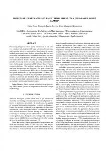
We first summarize our design process, goals, and necessary background on OpenSPARC and DySER. Our overarching goal was to determine the feasibility of the claim that DySER is a practical and non-intrusive solution that can be integrated with a commercial processor. To this end, our primary implemenation goal was to take the DySER design [7], which had been verified to some extent as stand-alone Verilog, and produce an implementation of DySER integrated as an accelerator block into the OpenSPARC processor. We call this OpenSPlySER. We had the additional requirements that the prototype be able to boot an unmodified operating system, and run real applications to completion. The ultimate goal of the software stack was to compile existing source-code transparently and without modification while using DySER efficiently. A fiveperson team was involved in accomplishing these goals: a three-person hardware design team to implement OpenSPlySER and a two person team to develop the software stack. OpenSPARC Background: OpenSPARC T1 is the open source release of Sun’s UltraSPARC T1. Its pipeline consists of six stages: fetch, thread select, decode, execute, memory, and writeback. It is a simple RISC processor lacking advanced architectural techniques such as staging and aggressive bypassing found in other in-order processors [2]. We ignore its multi-threading capability. DySER Background: The DySER architecture is built to exploit the insight that applications execute in phases and that a heterogeneous array of functional units can be configured into a specialized datapath matching these phases. A high-level design has been proposed and evaluated through simulation [7]. DySER assumes a profile-guided compiler that identifies these phases by determining common pathtrees of control-flow. It then slices these into a load-slice and computation-slice. The computation-slice is devoid of any accesses to memory and is thus a good candidate for specialization. In the execution model of this accelerator, the load-slice executes on a general purpose processor, which communicates with DySER using a simple set of ISA extensions. Figure 1 shows a high-level overview of DySER integrated into the OpenSPARC pipeline. More details on the architecture and program characterization on how well this execution model works are provided in [7].
Fetch
Thread Sel Thread Select
ICache
Decode
Execute
Decode
Switches
FU
Functional Unit Static config path
DCache S
S FU
S FU
S
S
S FU
FU
S
S
S
DySER OUTPUT INTERFACE
S
DySER INPUT INTERFACE
Register File
Memory Writeback
Execution pipeline
Dynamic Synthesized Execution Resources
Figure 1. OpenSPlySER with DySER integrated in execute stage.
The DySER block is built from a two dimensional array of functional units that support a heterogeneous mix of instructions. A switch array routes data between functional units. An input and output bridge serve as an interface between the processor and DySER to buffer data. They have a set of addressable ports that correspond to inputs or outputs for switches along the edge of the switch array. The switch and functional unit arrays are configured dynamically during execution to form a specialized datapath that matches the computation slice. Once configured, a DySER block looks and acts like a pipelined long latency functional unit. A 64 functional-unit DySER block with a mix of various 32-bit functional units occupy approximately the size of a 64KB SRAM. Two key features that differentiate DySER from other specialization approaches are i) its easy integration into conventional processor pipelines, and ii) its capability for supporting control-flow and arbitrary memory accesses because the load-slice executes on the main processor.
3
DySER: Taking the Concept to a Practical Implementation
To take the DySER architecture from design to a physical implementation, we had to undertake two steps. First, we had to evaluate whether the design was practical enough to implement and make a set of key refinements to the previously proposed DySER design. This design was well suited for integration into a commercial processor, and specifically, the basic tile architecture and the input/output interface required only small modifications. However, some mechanisms were too complex for a “real” implementation. These were related to DySER’s control flow execution, han-
dling of constants, output retrieval, and the issue of where the configuration information would be stored and how it would be read from memory and fed to DySER. Second, we had to design and implement some mechanisms which were previously conceptually ignored. These were related to debugging DySER applications, page faults and exceptions. We discuss these issues in detail below. Henceforth, we refer to the design from [7] as the “original design” to distinguish from our implementation. 3.1
Refinements for implementation
Control-flow and switch design: To support control flow inside the accelerator, DySER requires the implementation of φ functions, which determine the correct data values at merge points in the control flow. In the original design, these operations were assumed to be supported using a subset of the functional units. For our implementation, we moved this functionality to the switches to better use the FUs for computation. The switch design was modified to be able to examine data from two different ports and decide which to forward. This makes the switch more complex, but proved useful. Handling constants: The original design assumed that instructions that contained constants were assumed to be handled for “free”, without explicitly providing a mechanism. For this implementation, we developed an elegant solution that embeds the constant values as part of the configuration information. To implement this functionality, we allow the right operand of every FU to be configured to use an 8-bit sign-extended constant value instead of an input direction. These constants are sent once during configuration
and are always marked ready. This technique comes close to realizing the constants are “free” assumption. Configuration Path: In the original design, the configuration information would be stored consecutively in the application binary’s code segment, and a configure instruction would cause the processor to stream all the information to DySER. This design introduced various complexities in implementation. First, such a long multi-cycle instruction is hard to implement into OpenSPARC’s RISC pipeline tuned for single-cycle instructions. Second, where exactly to place these bits, and how to make them interact with the instruction cache, ITLB, etc. proved almost impossible to implement and this design was ultimately abandoned. Instead, we implemented a far simpler and effective solution. We designed the dyser init instruction as a single-cycle operation that partially configures the DySER block and embeds in its encoding some bits of the DySER configuration. A sequence of dyser init instructions fully configures the DySER block. The actual process of configuration was also radically simplified. The “original design” had a sophisticated proposal to form parallel scan-chains and configure the entire block in 10 cycles or so. Ultimately, that design was abandoned because setting up the parallel paths required many raw instructions or configuration bits from memory. With a single dyser init and SPARC’s single issue design, only 21 bits are available every cycle. Hence, what we implemented is as follows. When the dyser init instruction is executed, these 21 bits are sent to the DySER block to be shifted into the statically determined configuration path as shown in Figure 1, effectively creating a large, distributed shift register that shifts by 21 bits on each dyser init. Output Retrieval: The original design included an instruction called dyser commit. This instruction indicated that the current DySER invocation is over, and that DySER’s output values should be written to the appropriate registers or memory. Like the original dyser init instruction, the implementation of this instruction proved to be too difficult due to the complexities of integrating a long multi-cycle operation with OpenSPARC’s RISC pipeline. We solved this problem by defining the dyser recv instruction, which receives only a single value from DySER. Several of these instructions, along with dyser stores, are used to retrieve all output values. This modification also alleviates the need for the configuration to contain destination registers. 3.2
Additional mechanisms for implementation
Page-faults and Exceptions Our design choice for dyser init solved many of the subtle practical issues for
DySER. Cache misses, page faults, exceptions, and interrupts can all potentially disturb and interact with the configuration process. For DySER, these represent a variable length stall or unexpected termination of the configuration. Since configuration occurs as a sequence of dyser init instructions, any stall between two dyser init instructions is naturally handled. During the stall, the DySER block pauses configuration and stops shifting the configuration bits. Exceptions or other effects that cause an unexpected termination during configuration will leave the DySER block in an unknown, partially configured state. The DySER block will be in some configuration, but no data will be flowing through it. When execution resumes, the configuration also resumes as expected. Exceptions, interrupts, and context-switch of programs during DySER execution need additional OS support. The OS must be modified to “wait” until the DySER block finishes executing before swapping out the process. This has not been implemented and our prototype runs unmodified Ubuntu. In our system, only one application uses DySER at a time, so we can ignore this issue and still guarantee correct execution. Code Debugging Debugging code targeted for DySER is an important consideration for programmability. The compiler separates the code into two distinct sections: the loadslice and computation-slice. Instructions that are part of the load-slice execute on the SPARC processor using regular SPARC instructions, so existing debugging utilities like gdb can be used with no changes. Instructions that are part of the computation-slice are scheduled on the DySER block for execution. The internal state of DySER cannot currently be monitored from software. Debugging of the computation-slice is limited to monitoring the viewable processor state such as memory values and the register file. As part of our compiler verification, we built a “debugging” backend, that generates SPARC instructions for the computation-slice. This approach can be used by programmers debugging DySER code in a production environment as well.
4
OpenSPARC Integration
We now describe our extensions to the SPARC ISA and modifications to the OpenSPARC T1 processor to integrate DySER. To simplify our efforts, we used the singlethreaded version. 4.1
SPARC ISA Modifications
Table 1 provides a stylized listing of the assembly instructions added for OpenSPlySER. Table 2 shows the exact instruction encodings. dyser init, dyser send, and dyser recv are encoded via the impdep2 instruction in the
Instruction dyser init [config data] dyser send RS1 → DI1 dyser send RS1 → DI1, RS2 → DI2 dyser recv DO → RD dyser load [RS] → DI dyser store DO → [RS] dyser commit
Description DySER block placed in config mode, and the config data shifted in. Reads data from the register file and sends the data to a DySER input port. 1 or 2 source registers are sent to the specified DySER input ports. Write data from DySER output port DO to register RD. Read from memory address in register RS and send result to DySER input port DI. Writes data from DySER output port DO to memory using the address in register RS. Signals DySER to write all ready data back to the register file and/or memory, allowing OOO execution. Unused in OpenSPARC.
Table 1. A stylized listing of the DySER instructions. Instruction dyser init dyser send dyser recv dyser load dyser store
10 10 10 10 10
config DI1[4:0] DO1[4:0] DI1[4:0] DO1[4:0]
110111 110111 110111 000000 000100
Instruction encoding config RS1[4:0] DI2[4:0] V RD[4:0] unused RS1[4:0] 0 1000000 RS1[4:0] 0 1000000
000 001 010 000 000
config RS2[4:0] unused RS2[4:0] RS2[4:0]
Table 2. Design of the DySER instruction extensions for OpenSPARC. SPARC ISA with bits [7:5] as the DySER instruction opcode. dyser load and dyser store are encoded as SPARC load/store type instructions. The instructions provide a means for the processor and compiler to configure and interact with the DySER block. dyser init: Once a dyser init is decoded, DySER is signaled to take the 21 configuration bits from the instruction in the execute stage. dyser send: A dyser send reads up to two values from the register file, specified by RS1 and RS2, and pipelines the data to the DySER input ports denoted by DI1 and DI2 respectively. Setting the ’V’ bit to zero sends only the first value. dyser recv: A dyser recv sends the results from a DySER output port, specified by DO1, to a register file destination, denoted by RD. It behaves no differently than a normal SPARC arithmetic instruction by pipelining the data and register destination from the execute stage to writeback. dyser load: dyser load loads data from memory directly into DySER, using the bits normally restricted for the register destination as the DySER port destination. The source address is specified by r[RS1] + r[RS2]. The dyser load is identical in every way to a normal SPARC load instruction except for bits [10:5], which are reserved for loading from alternate space. If no alternate memory is specified (as is the default case for OpenSPARC), then anything non-zero will throw an illegal instruction exception. We take advantage of this behavior by reserving the most significant alternate space bit as a one for dyser loads and dyser stores and remove them from being trapped by the illegal instruction logic. The difference between a load and a dyser load is that when the data comes back, it is forwarded to DySER instead of the register file. It is important to note that in nei-
ther the dyser load nor dyser store are we allowed to use immediate bits instead of a register operand. Loads with immediate values do not have the reserved bits for alternate space, making it very difficult to decode in our scheme. dyser store: As with dyser loads, dyser stores also take advantage of the alternate space bits for decoding. dyser stores behave similar to dyser recvs in that the data coming out of DySER is stored, but in memory. It is also similar to SPARC stores in that the ALU calculates the memory address destination. 4.2
OpenSPARC Pipeline Modifications
DySER is designed to be placed alongside the ALU in the execute stage of the SPARC pipeline (Figure 1), consuming operands from memory and the register file like an ALU, and producing data for memory or the register file. Careful modification was required to the decode, execute, and memory stages to ensure proper DySER functionality as well as normal pipeline behavior. The fetch, thread select, and writeback stages required no modification. Much effort was required to understand OpenSPARC through reverse engineering the Verilog RTL before making modifications. Details on the exact modifications are elaborated in a related technical report [3]. Table 3 summarizes all the changes showing the files modified, number of lines, and state added. Before arriving at this final implementation, 1000s of lines were modified and reverted. Of course, lines modified is not always a direct reflection of complexity or design effort. From our design experience, integrating with OpenSPARC’s MMU and implementing the dyser load and dyser send instructions were the hardest tasks. Our lessons learned section elaborates further.
File
Description
Decode RTL files Instruction Decode Fetch Control Thread Switch Long Latency Instruction Control sparc ifu thrcmpl Thread Completion Control sparc ifu ifu Fetch Thread Select Decode Unit’s Top Level Execute RTL files sparc exu byp Bypass Mux Module sparc exu ecl Execute Control sparc exu ecl wb Bypass Control sparc exu Top Level Execute Module (18 flip-flops added) Load Store Unit RTL files lsu stb rwdp Store Buffer Datapath lsu dctldp Store Buffer Control sparc sparc sparc sparc
ifu ifu ifu ifu
dec fcl swl swpla
Lines Modified 205 4 15 5 4 42
13 15 10 178
9 14
Table 3. OpenSPARC RTL modifications. All changes except to sparc exu add no state.
An input and output interface supports the interaction between the OpenSPARC T1 pipeline and the DySER block. A DySER block has separate addressable input ports and output ports. Each input or output port contains a FIFO queue that buffers data taken in at the port specified by the dyser load or dyser send instruction. If a destination input queue is full or an output queue is empty, the processor stalls until space frees up or the data arrives, respectively. The final interface consisted of only 11 signals in the RTL as shown in Table 4. The relatively “small” changes and simple interface show that DySER integration is non-intrusive.
5
Software Stack
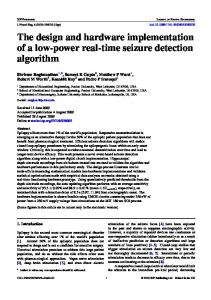
Tools: The approach we use for our software stack differs from prior DySER work [7] which performed program transformations at the binary level. In this work, we instead chose to operate on a compiler’s intermediate representation (IR), which was beneficial both in the short-term and longterm. In the short term, we were able to use existing analysis and compilation tools, and also leverage source level information that would be lost in the final binary. Using the IR also provides the long term advantage of being able to target multiple ISAs with little to no changes to our infrastructure. We chose the LLVM compiler framework and its associated IR primarily because of its ease of development. Compilation Flow: Figure 2 shows the compilation flow, from source to binary. First, we perform profiling to determine frequently executed code regions. During the slicing
stage, we use these profiles to decide what code to specialize, and how. Then, instructions marked for DySER are scheduled onto particular DySER functional units. Finally, a configuration is generated from these schedules, and the final binary is created. Profiling: To find frequently executed regions of code, we use known code profiling techniques. Not only does this provide us with execution frequency information, but we also use this stage to build what we call “path-trees”. These are single entry, multiple exit regions of code which do not cross function call boundaries. The profile information associated with each path-tree is referred to as a path-tree profile. These regions are the target for specialization in our compilation framework. Slicing: The first step in our slicing stage is to make all path-trees completely independent of each other. This involves duplicating a small amount of code, and making some control flow modifications. Each path-tree is then considered for slicing. The basic premise of the slicing algorithm is simple: load instructions, and other instructions on which these loads depend, are to be executed only on the processor pipeline. The remaining instructions are “pure computation” and are suitable for execution on DySER. The portion of the path-tree which can be executed in DySER is termed the “computation-slice” and the portion of the pathtree which is executed on the host processor is termed the “load-slice”. In our previous DySER work we showed that the computation-slice accounts for 59% to 95% of execution time. Since this entire work is on the compiler IR, it reduced our implementation time, eliminated spurious memory accesses due to register spills, simplified the slicing and the PDG-to-DySER mapping steps, and allows easy back-end retargetting. Scheduling: After determining the computation-slice, we have to map these LLVM IR instructions to DySER functional units. Also, we need to create a routing for all communication between instructions. To accomplish this cleanly, we use another intermediate form called the Program Dependence Graph (PDG). Here, both control and data dependences are represented as edges between instructions. Each node in the PDG will be mapped to a DySER node, and each edge in the PDG will be mapped as a series of routes though DySER’s switches. Program controlflow, which is represented with φ functions, is implemented by assigning them to switches and mapping paths for input values for the φ function into the switch. The goal of the scheduler is to achieve efficient schedules in terms of critical path length (speed) and overall switch utilization (power). Our current scheduling algorithm traverses the PDG in topological order, attempting many locations for each node, and greedily selects the location with the most efficient routes. Routing is accomplished through a simple but optimal breadth first search algorithm. It is possible that,
Signal Name dyser config enable dyser send enable0(1) dyser receive enable0(1) dyser sendport0(1)[4:0] dyser dyser dyser dyser
receiveport0(1)[4:0] commit write mux select
dyser reg dest[4:0] send data r0(1)[63:0] dyser data out0(1)[63:0]
Description Inputs Signals DySER to take incoming configuration data. Enabled on a dyser init Signals DySER to receive data incoming from register file specified by RS1(2) Signals DySER to send results from DySER ports specified by dyser receiveport0(1) to register specified by dyser reg dest. High on dyser recv Address that specifies DySER input ports where data from register file goes. dyser sendport1 is only used when two register sources are specified by dyser send instruction Address that specifies port on DySER that writes to the register file Signals DySER block to commit. Enabled on dyser commit instruction Register file write enable for dyser recv instructions. Enabled on dyser recv instruction Selects DySER output signals from muxes in execute stage, which include dyser write, dyser data out and dyser reg dest Register destination for dyser data out on a dyser receive Data from the register file sent to DySER on a dyser send Outputs Output data from DySER block to be written into memory or a register. dyser data out1 can be used as the address where dyser data out0 is stored in memory
Table 4. The microarchitectural interface between DySER and OpenSPARC with signal descriptions.
during scheduling, some nodes cannot be scheduled due to resource or routing limitations. The instructions associated with these nodes are returned to the load-slice, which we call computation-slice spilling. Again, LLVM’s design and API made this straight-forward to implement. Binary Generation: In this stage, the program is altered to complete the slicing process. First, configuration bits generated using the schedules from the previous stage are inserted at the start of the path-tree. A path-tree with self loops will branch to a point just after the configuration so that configuration time can be amortized. Computation-slice instructions are removed from the load-slice, and communication instructions (dyser send, dyser load, dyser recv) are inserted into the load-slice. Our simulation infrastructure is able to handle many of the SPECCPU2006 benchmarks. Specifically, six SPECINT benchmarks, bzip2, gobmk, h264ref, hmmer, libquantum and mcf, compile and run to completion on the prototype. The remaining benchmarks suffer from system call problems. We did not include floating point units in this implementation and hence cannot run the SPECFP benchmarks.
6
FPGA Prototype Implementation
Verification: We verified the RTL using a fairly straightforward bottom-up approach before FPGA mapping. We concentrated on ensuring the new DySER-based functionality performed as desired, while always checking that the pre-packaged SPARC regression tests (which do not use DySER) never failed. Collectively, our verification efforts consisted of unit-level testing of the DySER module, RTL
simulations of the modified OpenSPlySER pipeline, and FPGA emulation of the full-system running applications under the Ubuntu 7.10 operating system. We further ran specific targeted tests to verify exceptions and ITLB behavior for the DySER instructions. We used Synopsys VCS for verification and the Xilinx suite for FPGA mapping and verification. For FPGA bring-up and simulation, we followed instructions from the OpenSPARC design guide.
FPGA Prototyping: The OpenSPARC processor included the processor core and other modules around it for I/O etc. All of our changes were restricted to the OpenSPARC core; we were able to leverage the prepackaged support for memory controllers, Ethernet controllers etc. OpenSolaris proved problematic, so we used Ubuntu 7.10 for our operating system. We used a Virtex5 board with a XC5VLX110T FPGA for prototyping. Ultimately, we did not have to expend significant effort for physical design. We knew from the start that the 64 functional unit DySER would not fit on the board (more elaboration in Section 8). Due to switch and routing congestion on the FPGA, LUT utilization increases quadratically with the number of FUs in DySER. For this reason and for sensitivity studies, the DySER module, how it integrated with the processor, and the software-stack was parameterizable for DySER “size” which includes number of functional units and datapath width. Ultimately, we could fit a 2x2 DySER with 32-bit functional units, a 4x4 DySER with 8-bit functional units, or an 8x8 DySER with 2-bit functional units. We synthesized and mapped each of these, and their utilization characteristics are shown in Table 5. We emphasize that this is an FPGA prototyping limitation and does not
Application Source code
Profiler PathTree Profile
PathTree Transform Modified CFG
PathTree Analysis
Scheduler
Spill info
Load slices Slicer Transform Load & comp slices
Slicing info
Comp slices
Code generator binary
DySER config
config bits
Figure 2. Compiler Implementation. reflect that DySER is prohibitively expensive compared to OpenSPARC. Based on synthesis on a standard-cell library, 8x8 32-bit DySER occupies area similar to a 64KB SRAM. Our first result is that the prototype works, boots unmodified Linux, and runs several SPECINT benchmarks compiled through our toolchain correctly and to completion. As a further demonstration of DySER’s lack of intrusiveness, the critical timing path remained within the OpenSPARC pipeline regardless of which DySER configuration was used. The OpenSPARC design had a critical path of 10.1ns. With DySER integration, OpenSPlySER had a critical timing path of 12.7ns. The critical path (startpoint signal to end-point signal) of the processor remains the same between OpenSPARC and OpenSPlySER, i.e. neither the blocks in DySER or blocks/paths added to interface with OpenSPARC are on the critical path. The reason for the numerical difference of 10.1ns to 12.7ns is that with OpenSPlySER about 40% of the FPGA is devoted to DySER and it introduces additional routing delays. Hence, although the logical path is the same, its numerical delay is different. Due to the FPGA size limitations, the largest 32-bit datapath DySER block we could integrate for FPGA execution of OpenSPlySER was 2x2. On this configuration, little speedup is possible: the sends and receives introduce overheads, and many path-trees in real applications require more than four computation instructions. Thus, our prototype is of limited value in performance evaluation of complete applications. This paper’s primary goal and contribution though is not performance evaluation, but a demonstration that DySER is practically implementable. An 8x8 or 4x4 DySER is required to provide meaningful performance improvements. We are considering three FPGA-specific design optimizations in the future as part of a prototype performance evaluation: building a virtual 32-bit datapath out of a 2-bit datapath, but consuming 16 cycles across every link, multi-board simulation, and implementing a stateful DySER that can emulate a larger stateless DySER.
7
Performance Evaluation
We now discuss performance results of hand-optimized kernels and briefly discuss application results. Microbenchmark Results: We developed microbenchmarks to highlight individual features in DySER and isolate application characteristics that perform well and that perform poorly on a processor containing DySER. We report results for the 2x2 32-bit DySER which represents a usable 32-bit datapath but with only 4 FUs and the 8x8 2-bit DySER which represents a realistic design point of 64 FUs, but with only a 2-bit datapath. This configuration allows us to understand the interface issues and design integration issues of a practical DySER unit, and obviously the 2-bit datapath provides little usable functionality on real applications or benchmarks. The execution times are measured (in terms of clock cycles) from FPGA execution, excluding loader time etc. We report speedups compared to the OpenSPARC and note that both designs operate at 50Mhz. Table 6 describes the characteristics of the microbenchmarks. Because of the different number of FUs in the 2x2 and 8x8 DySER, the microbenchmarks are different. Figure 3 shows speedup for four microbenchmarks run on OpenSPlySER with a 2x2 DySER block and 8x8 DySER block. In general, we see that well tuned microbenchmarks are able to sustain the close-to peak performance of DySER. For the in-order machine, the sends and receives are the primary bottleneck. The maximum speedup for OpenSPlySER is given by the number of functional units in DySER divided by the time to send and receive all the inputs and outputs. Thus in best case, it is 32 for 8x8 DySER. We also ran these same microbenchmarks on our simulator to validate its accuracy. Our simulator was built on top of M5-SPARC and adjustments were made to make it cycle accurate with OpenSPlySER. The grey bars in Figure 3 shows its predicted speedup. Errors ranged between ≤ 1% to 5%. The main source of error is the difference in the modeling of the memory system.
Available # Slice Registers # Slice LUTs # Logic LUT # Memory LUT
OpenSPARC
69120 69120
19634 31010 29187 1823
17920
OpenSPlySER 4x4 8bit DySER 37027 55706 52540 3166
2x2 32bit DySER 36404 58288 55130 3159
8x8 2bit DySER 38579 63032 59865 3167
Table 5. OpenSPlySER FPGA utilization with different DySER blocks. Proto Simulated
1.5 1.0 0.5 0.0
K1
K2
K3
2x2 DySER
35
Speedup over Baseline
Speedup over Baseline
2.0
25 20 15 10 5 0
K4
Proto Simulated
30
K5
K6
K7
8x8 DySER
K8
Figure 3. Normalized speed-up of microbenchmarks on OpenSPlySER with 2x2 32-bit DySER and 8x8 2-bit DySER blocks. Results from FPGA-prototype and our M5 Simulator are shown.
Complete Application Results: Since our FPGA prototype for a 32-bit datapath allows only a 2x2 DySER block, performance speedups on complete applications are practically insignificant. We briefly present performance analysis from our validated prototype simulator which has an accuracy of 5% and can support various DySER configurations. We present results for OpenSPlySER with an 8x8 DySER and also contrast with the performance results in the original DySER work [7]. Table 7 compares speedup to the baseline processor considering a representative sample of 100 million instructions. The speedups are not very significant for two reasons. First, additional compiler work is required to improve the size of the path-trees. Second, and more importantly, SPARC’s single issue, in-order instruction retirement limits path-tree scheduling and thus performance. Because of its instruction retire semantics, we could not overlap multiple DySER invocations, unless software pipelining was possible with simple loops. These speedups are also much lower than previous DySER results, which demonstrated speedups for DySER integration with a single-issue core as shown in the column labeled [7] in Table 7. Our prototype’s results are lower for the three following reasons. i) The main reason is the OpenSPARC’s implementation of the load instruction. On OpenSPARC every load introduces at least a 3cycle bubble in the pipeline. In our original design evaluated in [7], we assumed a sophisticated in-order processor
which allows other independent instructions to proceed behind the load (thus allowing overlap of sends with loads, etc.) and assumed the FIFOs in the output interface could decouple this retirement problem. ii) A secondary source for lower performance is the compiler. Previously, we used gcc-produced binaries transformed for DySER. For the prototype, we use LLVM and compile from source. LLVMproduced code remains sub-optimal to gcc code — loop unrolling, for example, is done only when the loop-bound is static, and hence the path-trees are smaller. iii) A final source for the differences is that with our LLVM infrastructure, some control-flow instructions are replicated in the load-slice. To summarize, the performance results on microbenchmarks show that “well-behaved” programs can extract good performance. On more irregular programs, the baseline processor must have some latency hiding techniques else speedup from DySER is limited. Without modifying the OpenSPARC pipeline, adding some form of software pipelining can improve performance on loops that are executed many times. A detailed performance evaluation, which requires further compiler tuning and FPGA-specific optimizations, is on-going work.
8
Lessons Learned
We conclude with lessons learned under three categories: hardware, software stack, and FPGA implementation.
Name
dyser send
dyser recv
K1 K2 K3 K4
1 2 2 1
1 5 5 1
K5 K6 K7 K8
1 1 4 8
Pipelined?
Notes
Microbenchmarks for OpenSPlySER with 2x2 DySER Yes Best case example Yes “Regular” kernel; many inputs and outputs No Same as K2 but no s/w pipelining No Reconfigured every invocation Microbenchmarks for OpenSPlySER with 8x8 DySER 1 Yes Best case example 1 Some Less s/w pipelining compared to K5 8 Yes Moderate number of sends and receives 8 Yes Large number of sends and receives
Equivalent SPARC inst. 4 7 7 4 64 64 64 64
Table 6. Description of the microbenchmark kernels. Benchmark bzip2 hmmer h264ref
Proto 8% 9% 11%
[7] 50% 130% 36%
Benchmark gobmk libquantum mcf
Proto 7% 1% 0.2%
[7] 20% 9% 30%
Table 7. Speedup over baseline processor. 8.1 Hardware Design and Implementation ISA extensions: Fitting the additional DySER instructions in the SPARC ISA proved to be far less problematic than we initially had thought. Early on we noticed that there is very little room for new instructions in the SPARC ISA due to how compact it is in the first place. However, the SPARC ISA does include some flexibility in the form of two implementation dependant instructions. Fortunately, one of these was available and was adequate for all of our needs. Because the dyser init, dyser send, dyser recv, and dyser commit instructions are similar to a typical SPARC arithmetic instruction, we encoded them in the same fashion. The source registers from the register file for a dyser send (and the register destination of a dyser recv) are encoded into the same bits as any other SPARC arithmetic instruction. This allows the pipeline to be ignorant of the additional instructions and carry on as it normally does. Most SPARC arithmetic instructions do not use bits [12:5], so we used bits [7:5] for the DySER opcode. In the end, we purposefully modeled our nonmemory DySER instructions after the SPARC arithmetic instructions closely, so that built-in mechanisms like forwarding and register data fetching needed little modification. Don’t reinvent the wheel: A simple way we found to cut down additional hardware (along with additional verification) was to find ways of reusing the SPARC provisions or our own pre-existing hardware, similar to the way we took advantage of SPARC ISA conventions. As we developed the nature of how the DySER instructions interact with the pipeline, we noticed that on a fundamental level, dyser send and dyser load behaved nearly identically, as did dyser recv
and dyser store. Since they only differ in whether data is coming from or being written to a register or memory address, no additional DySER-SPARC interface signals for dyser load and dyser store were needed. Hardware overhead in the decode stage for adding DySER memory instructions only required adding one extra bit for whether or not a DySER operation uses the register file or memory. Co-designing OpenSPlySER and the compiler: The codesigning or co-refinement of the DySER hardware with the software compiler was an important contributing factor to the success of the project. Primary examples of the importance of co-designing the hardware and compiler for DySER were the embedded constant values and control flow execution. Performance is improved by sending the constants to DySER once only during configuration rather than on every invocation. While control flow execution in DySER is also not needed for correctness, designing the hardware to support control flow execution efficiently gives the compiler more flexibility in scheduling. DySER’s design is indeed simple: DySER was designed to be non-intrusive. This implementation confirms that it indeed is. The simple modular design of DySER made it easy to integrate into OpenSPARC. The interface between DySER and the processor is simple, entailing only 4 basic operations. The processor can configure, write data to, read data from, and send a commit signal to DySER. The process of configuration was also chosen primarily because it was a simple design. Each 32-bit dyser init instruction encodes 21 bits of configuration information that is shifted into the DySER block. Interrupts, stalls, and exceptions are handled naturally by the processor. These benefits were a significant contributing factor to get a configurable DySER block running in the OpenSPARC processor. The configuration interface specifies that configuration occurs in 21-bit increments with no other restrictions. This means the bit ordering and number of configuration bits per DySER component has no effect on how configuration oc-
curs. This separation makes it easy to change or extend the internal configuration. An example is when embedded constants were added to the functional units.
be scheduled. Similarly, we realized a typed dyser send for integer and floating point datatypes provided several performance benefits - this was trivial to achieve.
Understand the implementation (not just the design): We found that learning the idiosyncracies at the RTL level took the longest time among the design, implementation, and verification stages. Understanding the behavior goes a long way when debugging changes, especially when the design exhibits unexpected behavior. For example, while providing DySER the ability to stall the processor pipeline, we realized that our idea of stalling the processor’s pipeline was different from what OpenSPARC actually does. Another important reason to study the RTL is that it provides a better idea of design decisions made by the original team and perhaps the reasoning behind them. This can then provide key insights about design modifications. For example, SPARC decodes register operand information in the thread select stage, not the decode stage. SPARC also has its own methodology of where to put pipeline latches in the code. Understanding these and the myriad of other decisions helped our team to correctly interface with OpenSPARC.
Comparison to other compiler efforts: We summarize with some thoughts on our compiler bring-up in relation to three previous compilers: Multiscalar [19], IMPACT [1], and TRIPS [14]. We went from nothing to a full-fledged compiler pass that provides retargetable code to different ISA in about 5 months, with two full time graduate students. In some ways, the path-profiling, slicing, spilling, and scheduling are more sophisticated and place more restrictions on our compiler, than compilers for Multiscalar, IMPACT, or TRIPS. While those projects were from a different decade, their initial bring-up time (not time for optimized code) varied from 36 person-months to 96-person months. Significant effort had been expended in parsing, developing data-analysis passes and back-end code-generation. From day one, our effort was spent toward analysis passes need for DySER and not in basic infrastructure. In our opinion, LLVM’s sophistication gives researchers more freedom in contemplating compiler-heavy projects.
Must understand every detail: The unifying lesson that we learned modifying a commercial CPU is that it is equally important to understand the big picture as well as the bottom-most level of detail. The best way to accomplish this is to spend time thinking about modifications long before a single line of code is written. The time spent coming up with better solutions is time saved undoing invasive and undesirable changes that may break functionality. The more invasive a change is, the more likely it may unknowingly break other functionality. 8.2
Compiler Design and Implementation
LLVM’s IR is extremely powerful: In several ways we found LLVM’s IR and modular design extremely useful. It does not have a steep learning curve as GCC does, and is easily retargetable to different back-ends. However, its generated code quality, as of LLVM 2.8 for SPARC is worse than GCC 4.4.0, however. GCC-level translator impossible to maintain: We had initially started with a translator of GCC’s generated code. In many ways this was impossible to analyze, extend, and use to support various ISAs. So we moved the analysis into LLVM’s IR. This allowed us to trivially generate code targeting x86, SPARC, and ARM. Further, our entire compiler was split into multiple LLVM passes instead of being one large pass. Thus, we could run these in different order or multiple times if necessary. This proved crucial in implementing spilling - that is folding instructions from the computation-slice back to the load-slice when parts cannot
8.3
FPGA Prototyping
Overall, FPGA prototyping turned out to be problematic in several ways. The initial OpenSPARC bringup proved more tedious than we expected as many things in the documentation did not quite work. Bring up of the final OpenSPlySER was straight-forward after we had succeeded with OpenSPARC. Ultimately, our ideal goal of fitting a 64 function-unit (8x8) DySER block remain unfulfilled, due to insufficient FPGA density. To fit this large design, we will need a larger board than the Virtex-7 (due to the quadratic growth mentioned before). Building a parameterizable DySER block allowed us to build a 4x4 DySER with internal 8-bit datapath. While we could not run full benchmarks, this allowed us to run several microbenchmarks. A straight-forward set of tools for multi-board FPGA simulation would have helped significantly.
9
Concluding Thoughts
The DySER architecture was previously proposed for non-intrusively adding dynamic specialization capability to a conventional processor. This work demonstrates the feasibility of integrating the DySER design into a commercial processor by implementing an FPGA prototype based on the OpenSPARC T1 processor. The complete software stack of a compiler that builds the path-trees needed for specialization was also constructed. The prototype shows that it delivers on the goal of non-intrusive integration. The question of what we learned from the prototype that we
did not know from simulation poses a unique perspective for DySER. Non-intrusive integration was a primary goal which cannot be demonstarted without an actual implementation. While our initial work developed standalone DySER RTL as proof-of-concept, this prototype building exercise confirms it delivers on its goal of non-intrusive integration and confirms the design assumptions we made were largely valid. Several of the system integration issues which we abstracted away had to be designed first and then implemented. They all proved tractable without introducing significant complexity. Much compiler work and detailed performance evaluation is required to confirm if it delivers on its goal of performance improvement when integrated into a real processor. Our design serves as a good starting point to converge toward what an “accelerator” framework should be when integrating into a known core. Based on our experience, the following three principles seem most important: i) a simple set of mechanisms to interact with the processor core pipeline, perferrably accessing only register state; ii) a well defined interface for accessing memory or avoiding direct memory access; and iii) some mechanism to handle issues like precise exceptions and debugging. More broadly, such prototype implementation is required to understand subtle design and integration issues that cannot be uncovered until implementation time. Ultimately the significant advances in CAD tools, LLVM compiler technology, and pre-packaged FPGA development suites prove that small design teams can effectively build prototypes around OpenSPARC. Our work demonstrates this as a viable route for researchers.
Acknowledgments We thank the anonymous reviewers and the Vertical group for comments. Support for this research was provided by NSF under the following grants: CCF-0845751, CCF-0917238, and CNS-0917213. Any opinions, findings, and conclusions or recommendations expressed in this material are those of the authors and do not necessarily reflect the views of NSF or other institutions.
References [1] Impact compiler. http://impact.crhc.illinois.edu/. [2] M. Baron. Cortex-A8: High speed, low power. Microprocessor Report, 2005. [3] J. Benson, R. Cofell, C. Frericks, C.-H. Ho, V. Govindaraju, T. Nowatzki, and K. Sankaralingam. OpenSPLySER: The Integrated OpenSPARC and DySER design. Technical report, Department of Computer Sciences, The University of Wisconsin-Madison, Madison, WI, 2012. [4] T. J. Callahan, J. R. Hauser, and J. Wawrzynek. The garp architecture and c compiler. Computer, 33:62–69, April 2000.
[5] N. K. Choudhary, S. V. Wadhavkar, T. A. Shah, H. Mayukh, J. Gandhi, B. H. Dwiel, S. Navada, H. H. Najaf-abadi, and E. Rotenberg. Fabscalar: Composing synthesizable rtl designs of arbitrary cores within a canonical superscalar template. In ISCA ’11. [6] M. Fillo, S. W. Keckler, W. J. Dally, N. P. Carter, A. Chang, Y. Gurevich, and W. S. Lee. The m-machine multicomputer. In MICRO ’95. [7] V. Govindaraju, C.-H. Ho, and K. Sankaralingam. Dynamically specialized datapaths for energy efficient computing. In HPCA-17, 2011. [8] S. Gupta, S. Feng, A. Ansari, S. Mahlke, and D. August. Bundled execution of recurring traces for energy-efficient general purpose processing. In MICRO 2011. [9] R. Hameed, W. Qadeer, M. Wachs, O. Azizi, A. Solomatnikov, B. C. Lee, S. Richardson, C. Kozyrakis, and M. Horowitz. Understanding sources of inefficiency in general-purpose chips. In ISCA ’10. [10] M. Hempstead, G.-Y. Wei, and D. Brooks. Navigo: An early-stage model to study power-constrained architectures and specialization. In Workshop on Modeling, Benchmarking, and Simulation, 2009. [11] J. H. Kelm, D. R. Johnson, M. R. Johnson, N. C. Crago, W. Tuohy, A. Mahesri, S. S. Lumetta, M. I. Frank, and S. J. Patel. Rigel: an architecture and scalable programming interface for a 1000-core accelerator. In ISCA ’09. [12] C. Lattner and V. Adve. LLVM: A compilation framework for lifelong program analysis & transformation. In CGO ’04, pages 75–88. [13] K. Sankaralingam, R. Nagarajan, R. McDonald, R. Desikan, S. Drolia, M. Govindan, P. Gratz, D. Gulati, H. Hanson, C. Kim, H. Liu, N. Ranganathan, S. Sethumadhavan, S. Sharif, P. Shivakumar, S. W. Keckler, and D. Burger. Distributed Microarchitectural Protocols in the TRIPS Prototype Processor. In MICRO ’06. [14] A. Smith. Explicit Data Graph Compilation, PhD Dissertation, UT-Austin, 2009. [15] A. Solomatnikov, A. Firoozshahian, O. Shacham, Z. Asgar, M. Wachs, W. Qadeer, S. Richardson, and M. Horowitz. Using a configurable processor generator for computer architecture prototyping. In MICRO ’09. [16] S. Swanson, A. Putnam, M. Mercaldi, K. Michelson, A. Petersen, A. Schwerin, M. Oskin, and S. J. Eggers. Areaperformance trade-offs in tiled dataflow architectures. In ISCA ’06. [17] M. B. Taylor, J. Kim, J. Miller, D. Wentzlaff, F. Ghodrat, B. Greenwald, H. Hoffman, P. Johnson, J.-W. Lee, W. Lee, A. Ma, A. Saraf, M. Seneski, N. Shnidman, V. Strumpen, M. Frank, S. Amarasinghe, and A. Agarwal. The raw microprocessor: A computational fabric for software circuits and general-purpose programs. IEEE Micro, 22:25–35, March 2002. [18] G. Venkatesh, J. Sampson, N. Goulding, S. Garcia, V. Bryksin, J. Lugo-Martinez, S. Swanson, and M. B. Taylor. Conservation cores: reducing the energy of mature computations. In ASPLOS ’10. [19] T. Vijaykumar. Compiling for the Multiscalar Architecture, PhD Dissertation, UW-Madison, 1998.