negotiation and high speed run on a road surface having random profile. All these tests completed successfully and vehicle validated the design process prior to.
MATEC Web of Conferences 95 , 09007 (2017)
DOI: 10.1051/ matecconf/20179509007
ICMME 2016
Design, Modeling and Virtual Validation of Mobility platform of Tracked Vehicle Syed Talat Shabbir and Chen Hui-yan School of Mechanical and Vehicular Engineering Beijing Institute of Technology, Beijing, 100081, China
Abstract. Hull design of a tracked vehicle plays a critical role in the vehicle mobility, crew protection and combat performance. This work is intended to design a hull of 50 Ton tracked vehicle using conventional layout of suspension and running gear components. Driver compartment of hull is designed based upon driver height of 1.69m. Critical hull parameters such as angle of departure, location of 1st road wheel w.r.t idler wheel, location of last road wheel w.r.t sprocket and distribution of middle road wheels are calculated. Finally, designed hull is modeled in Pro/Engineer software and Recurdyn software is used to ascertain vehicle performance in various prototype tests. In the wake of scarcity of papers on this subject, this paper not only outlines the process of hull design for conventional tracked vehicles but also for unconventional ones such as autonomous tracked vehicles .
1 Introduction
2.2 Length of the hull.
The mobile platform of the tracked vehicle, which can carry the turret with or without gun, is called as the hull of a tracked vehicle. This platform or hull ensures high mobility and protection in combat condition. Three main characteristic of the tracked vehicle are fire power, mobility and protection [1]. The hull of tracked vehicle has very high relation to the mobility and reasonable relation to the protection. The purpose of this study is to design a mobility platform of a tracked vehicle and to investigate its performance prior to field testing. In the course of design of high speed tracked vehicle, number of field tests are required to analyse the performance of designed vehicle. Development cycle based upon field testing is long and cost intensive. Therefore, mathematical design and simulation process is adopted for initial design calculations of mobility platform of 50 Ton tracked vehicle. Designed mobility platform is investigated by using multibody dynamic simulation in Recurdyn program.
Again the ergonomic studies on tracked vehicles and practical experience indicates that the driver should have some suitable distance at his disposal for his body and controls. Here the height of the man considered is 1.69 m tall. Including the protection thickness of the front nose gives the length from front to the driver's compartment.
2 Hull design 2.1 Height of the hull In Asian standard a driver's compartment with a height of 900 - 1000 mm and a suitably designed seat a man can be easily accommodated in the compartment. This information is from the ergonomic study of a man and experience [2]. We cannot play much with this height or increase it to our desire since it effects the overall height of the tracked vehicle.
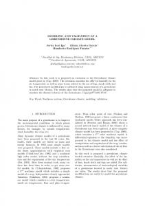
2.3 Width of the hull The width of the tracked vehicle would be restricted by the railway carriages and the transporters to be used for the tracked vehicles. The performance or steerability would also be effected by too wide or too narrow tracked vehicle. As an experience the hull width is generally kept up to 2 meters. This would end up with the tracked vehicle width up to 3.5m. 2.4 Design of hull profile. Following steps indicate the procedure for hull profile design. First we draw a line to indicate the ground. Next draw a reference line 470mm higher from the ground line to represent ground clearance. Now draw a line at a height of 990 mm to represent driver’s compartment. Draw another horizontal line in the front at a height of 0.85 meters which is the required vertical obstacle crossing capability of the tracked vehicle. Now place the nose tip at the 0.85 m high line. If it is lower the tracked vehicle will have difficulty in negotiating vertical obstacles. Idler wheel position is determined on the basis of the required angle of approach for the tracked vehicle. Draw a line at 8° from the tip backward to mark the
© The Authors, published by EDP Sciences. This is an open access article distributed under the terms of the Creative Commons Attribution License 4.0 (http://creativecommons.org/licenses/by/4.0/).
MATEC Web of Conferences 95 , 09007 (2017)
DOI: 10.1051/ matecconf/20179509007
ICMME 2016
R1 = vertical distance of shock absorber from bottom;
profile of the top plate cutting the 990-mm height. Angle of 8° is the angle with the nose armour. If it is reduced the blind zone of the driver would increase.
�
= shock absorber and sprocket clearance (7~10mm)
8⁰
O2O5 � (O1O2 )2 � (O1O5 )2
(3)
A � O2O5 � a1
(4)
a1 = distance of shock absorber center from torsion bar
�1 � tan �1
h O1O2
(5)
Now (Fig. 2)
�2 � sin �1 (
Figure 1. Frontal profile of hull
2.5 Layout of chassis/Hull.
)
(6)
� � �1 � �2
Center of Final drive
δ
Horizontal distance of Shock absorber from bottom plate
O3
O1
R1
a1
R2
Distance of torsion bar from Shock absorber
O5
Hull bottom Plate
Figure 3. Layout of torsion bar, shock absorber and Final drive
Location of the first road wheel is calculated with respect to idler wheel by keeping the angle of approach as 35° as shown in Fig. 4. Idler Wheel
(1)
Refer Fig. 2 to determine distance between center of final drive and torsion bar at sixth road wheel ( A ) Balance Arm
(7)
Center of shock absorber
Rb is radius of balance arm.[3], [4].
O1O3 � A1 � Rb
Balance arm radius
O D
Sprocket
Road Wheel
Torsion Bar
F
Φ1 Φ2
O2 h a
(O1O2 )2 � h2
Finally, angle of departure is as under
In designing running gear arrangement of a tracked vehicle, the critical parameters considered are location of 1st road wheel w.r.t idler wheel, location of 6th road wheel w.r.t sprocket, angle of approach, angle of departure and distribution of middle road wheels. The angle of approach is generally kept between 30-40° for modern tracked vehicles. Therefore, the hull is designed to negotiate a slope of 60% (31°) and vertical obstacle crossing of 0.85 meter. Angle of departure or angle between ground and rear can only be found after determining the position of the sprocket and the last road wheel. The location of the sprocket basically depends on the output of the engine through transmission and final drive. This gives us the starting point and is marked as O1 in Fig. 2 where sprocket radius is Rz , Rw is road wheel radius and
Rw � Rz
b Rb O3
O4
O1
Distance from Ground
E Road Wheel height
C Hull Height
RW Track height from ground
Φ
Angle of Approach = 35⁰ A
A
Between the sixth and the first road wheel we can now distribute the other 4 road wheels. Before doing the distribution, it is essential to determine the distance between the two torsion bars. The procedure to be adopted is for worst condition at maximum travel of
Figure 2. Angle of departure
O1O2 � R1 � RZ � �
B
Figure 4. Location of 1st road wheel from Idler
A1
(2)
2
MATEC Web of Conferences 95 , 09007 (2017)
DOI: 10.1051/ matecconf/20179509007
ICMME 2016 wheel no 6 in upward direction.
D1D2 is the distance
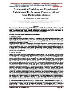
3. Virtual prototyping
between two road wheels which is calculated from the dimensions given in Fig. 5. D1 D2 is also the minimum
Virtual prototype of tracked vehicle [7,8] is built to perform field test prior to design finalization. These tests are costly and often dangerous when conducted on real prototype. In order to construct a virtual model of tracked vehicle we used two software namely Recurdyn and Matlab. 3D designed CAD model is imported in Recurdyn to add suspension and running gear components. Matlab is used to calculate design parameters such as suspension stiffness, damping ratio, etc. Random road profile is also generated in Matlab which is later used in Recurdyn to construct 3D road surface as shown in Fig. 7.
between other road wheels for which allowance is added according to the space requirement for suspension system. Road Wheel Clearance
Road Wheel # 6
Road Wheel # 5
D1 Rb D2 Rb Bottom Plate
Figure 5. Distance between road wheels
Calculation of layout parameters of hull are summarized in Table-1.
Figure 7. Random road surface
Table 1. Summary of Hull critical parameters.
S/No 1 2. 3. 4 5 6. 7. 8 9.
Balance arms, road wheels, sprocket, idler wheels are added to hull using revolute joints. A real damper curve is added to represent non-linear behaviour of damper. A “sphere-cylinder” connection is also used [9] to represent hydraulic limiter to restrain vertical motion of road wheel.
Critical Hull Parameter Distance b/w Wheels 1-2 850 890 2-3 890 3-4 890 4-5 5-6 882 Location of 1st Rd wheel 600 w.r.t Idler wheel (mm) 1038 Location of 6th rd wheel w.r.t Final drive (mm) Angle of approach 35° Angle of departure 22.2°
Figure 8. Assembled tracked vehicle without track
2.6 Hull modeling As per the design process outlined in previous section, hull is modeled in Pro/Engineer software [5, 6] which is best suited for parametric modeling. Designed hull exhibits 3 rotational and 3 translation DOF. Ride (pitch and bounce) and handling (yaw, sides slip and roll) characteristics of tracked vehicle are highly dependent on the design layout hull of tracked vehicle. If these motions are controlled the platform is considered to be stabilized. 3D CAD model of designed hull is shown in Fig. 6.
Vehicle speed
Figure 9. Assembled tracked vehicle with track
Constant speed 60 km/h
5-12sec. Acceleration to 60 km/h 0-5 sec. Motion stablization
Time (s)
Figure 6. CAD model of hull of tracked vehicle
Figure 10. Motion Input curve
3
MATEC Web of Conferences 95 , 09007 (2017)
DOI: 10.1051/ matecconf/20179509007
ICMME 2016 3.1 Motion input
provisioning the technical support and bearing the financial effects of our whole research and in particular for this work.
Motion input is given at revolute joints provided on sprockets. Step input relation is used to represent tracked vehicle acceleration from 0 to 60 km/h in 12 seconds. Vehicle speed curve is shown in Fig. 10.
References 1.
4 Results Various real field tests were conducted in Recurdyn software to ascertain the performance of designed hull for tracked vehicle. These tests include ditch crossing, slope negotiation and high speed run on a road surface having random profile. All these tests completed successfully and vehicle validated the design process prior to assembling a real prototype.
2. 3.
4.
5.
6. Figure 11. Tracked vehicle over rough terrain
7.
5 Conclusion In the wake of scarcity of papers on the design of tracked vehicle, a complete design process for the hull of tracked vehicle is outlined. Virtual testing of prototype validated the design process and it is inferred that simulation completed successfully and designed tracked vehicle passed prototype testing such as high speed run, trench and obstacle crossing. Design process can be further extended for selection and optimization of suspension and running gear components for different hull layouts.
8.
9.
Acknowledgement We gratefully acknowledge to NORINCO China (HITNORINCO PhD Scholarship 2013-17) and Vehicle Laboratory of Beijing Institute of technology, Beijing for
4
National Research Council Canada, Armour Combat Vehicle Mobility Development Study, (Phase 2 Report, 5 July 1999), 29-49. Richard Ogorkiewicz, Technology of Tracked vehicles II, Jane’s Information Group Ltd, (1991) Christian Guenther and Cornelius Leondes. Synthesis of a high-speed tracked vehicle suspension system - part I: Problem statement, suspension structure, and decomposition. IEEE. 22: 158-165, April (1977). Murakami M, Watanabe K and Kitano. A mathematical model for spatial motion of tracked vehicles on soft ground. Journal of Terramechanics, 29(1) :71-81, (1992). Zi-Yue, Ya-Dong GAO et al. Modeling and Simulation of tracked vehicle based on Pro/E and RecurDyn. 5th International Conference on Advanced Design and Manufacturing Engineering, (2015). ChangLiang Cai, Simulation of the tracked duct cleaning robot based on Pro/E and RecurDyn[J], Manufacturing automation, (11):53-56, (2014). Yin Huabing, Hu Licheng, Zhang Zhongsheng, Huang Yingxin. Modeling and simulation of virtual prototype for tracked vehicle with hydro-pneumatic suspension system. 6th Int. Conf. on System Simulation and Scientific Computing (Beijing). Oct. 24-27. (2005) C. Q. Ma, X. X. Liu, B. Q. Dai, "Research and Design of Mechanical System Virtual Prototyping", Applied Mechanics and Materials, 52-54, pp. 624629, (2011) RuiQiang and Wang Hongyan. Multi-body dynamic simulation and experimental validation of high-speed tracked vehicle. Proceedings of the 7th ICFDM 2006 International Conference on Frontiers of Design and Manufacturing, Guangzhou, China, pp: 31-34, June 19-22, (2006).