Sang Yoon Park*, Nam Ik Cho*, Sang Uk Lee*, Kichul Kim**, Jisung Oh* * *. *School of ... *DMS Lab, Samsung Electronics, Kyungkido, Korea. ABSTRACT.
DESIGN OF 2W4WSK-POINT FFT PROCESSOR BASED ON CORDIC ALGORITHM IN OFDM RECEIVER Sang Yoon Park*, Nam Ik Cho*, Sang Uk Lee*, Kichul Kim**, Jisung Oh* * *
*School of Electrical Engineering, Seoul National University, Seoul 151-742, Korea **Dept. of Electrical Engineering, University of Seoul, Seoul 130-743,Korea * * *DMS Lab, Samsung Electronics, Kyungkido, Korea ABSTRACT In this paper, the architecture and the implementation of a 2K/4K/SK-point complex fast Fourier transform (FFT) processor for OFDM system are presented. The processor can perform 8K-point FFT every 2 7 3 p , and 2K-point every 68.26~sat 30MHz which is enough for OFDM symbol rate. The architecture is based on the Cooley-Tukey algorithm for decomposing the long DFT into short length multi-dimensional DFTs. The transposition and shuffle memories are used for the implementation of multi-dimensional transform. The CORDIC processor is employed for the twiddle factor multiplications in each dimension. A new twiddle factor generation method is also proposed for saving the size of ROM required for storing the twiddle factors.
1. INTRODUCTION Discrete multitone is widely used for digital data transmission systems such as xDSL and digital video/audio broadcasting. Specifically, orthogonal frequency-division multiplexing (OFDM) is the standard for European digital terrestrial video transmission (DVB-T) system[ 13. In OFDM, the spectra of the subcarriers overlaps, and their spacing is chosen so that each subcarrier is orthogonalto all other subcarriers. Because ,the process of obtaining orthogonal subcarriers is realized by the discrete Fourier transform (DFT), efficient implementation of the DFT is one of the most important problems in OFDM systems. In the modulation and demodulation of OFDM system, it would be almost impossible to implement the generation of a large number of subcarriers in a parallel demodulator. Hence, it is implemented with the FFT processor of s u e 2" that is slightly greater than the number of subcarriers. A simplified block diagram of modulation and demodulation schemes based on the FFT processor is shown in Fig. 1. Each synchronous subcarrier generated by IFFT is not modulated by bandpass filtering, but by the baseband signal processing utilizing the orthogonal property of the base function of carriers. Due to the
0-7803-7080-510 lI$lO.OO 0200 1 IEEE
Fig. 1. Block Diagram of ModulatiodDemodulation Schemes in OFDM System large number of subcarriers in OFDM modulation, high speed and long FFT with sequentialinput data is needed. In this paper, we present an FFT processor that can perform 2K and 8K DFT for European standard, and also 4 K for Japanese standard. This paper is organized as follows. The FFT algorithm for the proposed system is given in Section 2. In Section 3, the description of entire architecture is given, and the multiplication and memory controller are also presented in detail. Section 4 gives the implemented chip feature. And Section 5 gives conclusions. 2. FFTALGORITHM
The N-point discrete Fourier transform is defined by N-I
X(k)=
z(n)W$
k = 0,1,...N - 1
(1)
n=O
where, WN = e - j ( 2 n / N ) .z(n)and X ( k ) are assumed to be complex numbers. There are various fast algorithms for the implementationof DFT,such as DIT (Decimationin-Time), DIF (Decimation-in-Frequency),Cooley-Tukey, and Winograd algorithms. Forthe 2"-DFT, Cooley-Tukey algorithm results in DIT or DIF algorithm[2]. In this
457
needed for convertingthe row-column order into columnrow order. Proposed structure is pipelined for the parallel processing of DFTs. Serial to parallel converter (SPC) and parallel to serial converter (PSC) are located between each DFT unit and memory system for efficient pipelining. Detailed description of multipliers, Th4 and SM will be given in the following subsections, and explanationon SPC and PSC are omitted.
paper, we implement the DFT according to the CooleyTukey algorithm,i.e., the long-IengthDFT is decomposed into short-length multi-dimensionaltransforms. By using the Cooley-Tukey algorithm, the architecture has modularity, and 2K/4K/8K selection mode is easily implemented. sum4.m
II
c Ounm
I
i
n
i
3.2. Complex multiplier
I
U
i
n
The 4point and 8-point DFTs are realized by direct implementation of the signal flow graph of decimation-intime FFT. For the efficient computation of the twiddle factor multiplication, we apply different methods to three different cases. 3.2.1. Two real multiplications
I
I
In 8-point FFT,the only twiddle factor that requires actual multiplication is cos(0.75~)f jsin(0.75~)(Other twiddle factor is Aj). Since the real and imaginary components are the same, two real multipliers are sufficient in the 8-point FFT module. The schematic diagram of complex multiplier for 8-point DFT is shown in Fig. 3.
U
n
n
Fig. 2. Block Diagram of the Proposed 2K/4K/8K FFT Structure
3. ARCHITECTURE In this section, we describe the architecture of proposed FFT processor in top-to-down order.
Fig. 3. The Schematic Diagram of Complex Multiplier for 8-point DFT
3.1. Entire architecture The main components of the proposed architecture are the short-length DFTs and transposition memory (TM) or shuffle memory (SM) for interfacing each short-length DFTs. The block diagram of the proposed 2K/4K/8K complex FFT processor is shown in Fig. 2. The 8K DFT is decomposed into 4 x 2K two-dimensional DFT by the Cooley-Tukeyalgorithm. The 2K-point DFT is again decomposed into 64 x 32 DFTs. They are again decomposed into smaller DFTs. The basic building blocks of the proposed method are the 4-point and 8-point DFTs, twiddle Edctor multipliers (Wl, W2,W 3 and W4 inFig. 2), and the memory controllers. Note that the TM is used in 64-point DFT,and the SM is used elsewhere, which are
3.2.2. Tlree real multiplications
For the implementation of twiddle factor multipliers in 64-point and 32-poht DFT modules (Wl and W3 in Fig. 2), we employ complex multiplier employing booth algorithm. Futhermore, we reduce the number of real multipliers by using the properties of trigonometric functions. More precisely, the twiddle factor multiplication can be expressed as
458
A x W E k = ( A ~ + j A 1x)( c o s 0 - j s i n 8 ) = (ARcos 8 + AI sin 8) + j ( A 1 cos 0 - ARsin 0 ) (2)
where A = AR + jAI is the input to the multiplier and Wgk = e-jsnk= e-jo. The terms in the righthand of the eq. (2) can be expressed as AR cos6 AIcosO
+ AI sin6 = &(sin6 + d)+ AI sin6 = (AR + AI) sin 0 + A R ~(3)
- ARsin6 = AI COS^ - A R ( C O S-~d) = (A, - AR) COS@ + A R ~(4)
where d = cos 6 - sin 6. From eqs. (3) and (4), it is observed that the complex multiplication can be performed with three real multiplications, whereas the conventional FFT implementations employ four real multiplications. As a result, the implementation of this method obtains 23% hardware saving as shown in Table. 1 (23,589 vs. 18,171gates) and about 0.007 lower RMS error than the conventional approach for the 12bit integer random inputs. 3.2.3. CORDICprocessor
In the twiddle factor multiplications for larger transforms (W2 and W4 in Fig. 2), the booth multiplier is not efficient because it requires large ROM for storing many twiddle factors. For example, the conventionalmultiplier with four real multiplications needs two ROM storage (cos and sin value) for every twiddle factor, which results in 81,920-bit ROM in the case of 8K-point FFT.In order to obviate such large ROM, we employ a complex multiplier based on the Coordinate Rotation DIgital Computer (CORDIC) algorithm[3] in this paper. Specifically, all the twiddle factor multiplications in FFT are formulated as a rotation of a 2 x 1vector in various coordinate systems. The CORDIC computationis to decomposethe angle of the twiddle factor into the weighted sum of a set of predefined elementary rotation angles. The CORDIC algorithm can be summarized as zi+1 = zi
-
Bi
.2-'
yi+1 = yi f ai .2-'
= z; - Bi * ai ai = tan-'(2-9 ui = sign(4i)
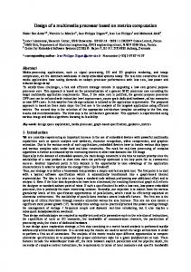
on the fact that if n x k in the eq. (2) is known, we can have the angle for the CORDIC processor. Since n x IC is equal to multiplication of row index by column index of memory address as shown in Fig. 4, the twiddle factor generator can be easily implemented using counter and circular shifter as shown in Fig. 5 . It can also be efficiently applied to all other FFT algorithms as well as Cooley-Tukey algorithm. Using the proposed scheme, not only the overall ROM size but additional hardwares such as word-line decoder and pull up registers, are significantly reduced as comparedto conventionalapproach, while the number of gates required for the complex multiplication is comparable as summarized in Table. l.
CORDIC PROCESSOR input
output
Circular Shifter
MxN-bit binary counter
Fig. 5. CORDIC structure using twiddle factor generation method
. yi *
Fig. 4. 'Twiddle factor generation method
zi
Zi+l
(5)
where [zi, yi] is the input vector and [zi+l, yi+l] is the output vector which is the result of rotating [zi,yi] by ui ai. The conventional CORDIC processor also requires 2560-word 17-bit ROM for storing gi in eq. (5) and additionalhardwares when 17 iteration processes are performed. Hence, we propose a twiddle factor generation method that obviates the ROM required for storing the twiddle factors in W2 and W4. This method is based
Table.1. Hardware Requirement of Complex Multiplier (given 16-bit for each sine and cosine value). Conventional approach
Proposed scheme
(real multiplierx4)
-
(WZ.W4)
ROM size
81,920-bit
&bit
&bit
Complex multiplier
23,589 gates
18.171 gates
26.9i4 gates
459
33. Memory control
ceeds the S N R of 45dB, which is enough for digital terrestrial TV broadcasting. The Proposed architecture has been synthesizedin the 1.8V 0.18pm CMOS technology. It results in about 600,000 gates for logic and storage.
For the implementationof DFT using the Cooley-Tukey algorithm, the memory control also plays an important role. We employ the transposition memory (TM) and shuffle memory (SM) in [4],which are the memory systems that convert row order to column order with the minimum amount of memory. For the N x N transforms, the conventionalTM can be used as shown in Fig. 2. But, for the M x N transforms, where M is not equal to N , SM can provide memory efficient architecture. Basic building blocks of SM are memory-cell-array using 3-TDRAM, address generator, word-line decoder, input data buffer, sense amplifier and bus driver. In particular, because bit lines of read mode can be operated independent of that of write mode in memory-cell-array using 3-T DRAM, consecutiveread-then-write at the same address can be performed with partitioning clock cycle. 8K-word shuffle memory, shown in Fig. 6, is decomposed into four 2K-word memory blocks and 2K-word memory subblock is again decomposed into eight 256word 3-T DRAM for the stability of read mode. 8Kword shuffle memory operates as 8K or 2K-word memory according to the block selection signal. Moreover, the proposed memory system has been designed to tolerate guard interval that is defined in OFDM system in order to combat the delay-spread distortion of transmitted data.
5. CONCLUSIONS
In this paper, we have proposed an FFT processor for the OFDM system. The architecture is based on the CooleyTukey algorithmto have modular structure and thus 2K/4K/8K point selection is easily achieved. Booth multiplier and CORDIC processor are employed for twiddle factor multiplications. For saving the ROM size in CORDIC processor, twiddle factor generator is also proposed. The overall 2K/4K/8K-FFTprocessor requires 600,000 gates and is implemented in 1.8V 0.18pm CMOS. The processor can perform 8K-point FFT every 273ps, and 2Kpoint every 68.26~sat 30MHZ, which exceeds OFDM symbol rate. 6. REFERENCES [11 M.Alard and R.Lasalle, ”Principles of modulation and channel coding for digital broadcasting for mobile receivers,” ZTU WARC-ORBConference., Sep. 1988.
[2] J.W.Cooley and J.W.Tukey, ”An algorithm for machine computation of complex Fourier series,” Math. Cornput., vol. 19, 1965 [3] Y. H.Hu, ”CORDIC based VLSI architecture for digital signal processing,” ZEEE Signal Processing Mag., pp. 16-35, July 1992.
[4]Kichul Kim, ”Shuffle memory system,” 1 3 4 Zntert
I
L
bloskmabk
T
national Parallel Processing Symposium., p p.268272, April, 1999.
I
Fig. 6.Structure of 8K-word Shuffle Memory.
[SI M.BEKOOIJ and J.HUISKEN, ”Numerical Accuracy of Fast Fourier Transforms with CORDIC Arithme tic,” JournaI of VUZ SignaI Processing., vol. 25, pp.187-193,2000. ,
4. CHIP FEATURES
Based on the fixed-point error analysis of the CORDIC forDFT[5],[6], we have analyzedthe finite precision rounding and approximationerror of the proposed system, and determined the appropriate word length. More specifically, the proposed system has been designed with 2 x 10bit input, 2 x 12-bit output, and 2 x 16-bit internal precision. Also, 5 extra bits are added and 17 iteration processes have been performed in order to guaranteethe accuracy of conventional complex multiplier. As a result, the performance of proposed FFT processor always ex-
460
[6] Y.H.Hu, ”The quantization effects of the CORDIC algorithm,” ZEEE Transactions on Signal Processing., vol. 40, No. 4,April 1992.