Design of a Digital PID Regulator Based on Look-Up Tables for Control of High-Frequency DC-DC Converters Aleksandar Prodić and Dragan Maksimović Colorado Power Electronics Center Department of Electrical and Computer Engineering University of Colorado at Boulder Boulder, CO 80309-0425, USA
[email protected] Abstract – This paper describes design of a digital PID regulator based on look-up tables for high frequency dc-dc switching converters. The use of the look-up tables instead of multipliers enables a small, low-power implementation and operation at high switching frequencies. Design guidelines are given for the resolution and size of entries in the look-up tables. A design example and experimental results are presented for a digital controller IC used to control a 1 MHz, 2.7 V, 3 W buck converter.
I. INTRODUCTION Digital controllers can offer a number of advantages over analog controllers, including flexibility, lower sensitivity, and programmability without external components [1-6]. Figure 1 shows a digitally controlled switching converter. It consists of an analog-to-digital converter, a processing unit (regulator) that implements a control law, and a digital pulse width modulator (DPWM). In order to achieve dynamic characteristics comparable with analog PWM controllers, fast implementation of a discrete-time control law is required. For cost-driven low-power, high-frequency applications, simplicity, small size and low power consumption are important. In order to implement a digital controller for these applications, hardware optimization is needed. The hardware requirements that DPWM and + Vin
Switching Converter
Load
Vout(t)
-
analog-to-digital converter have to satisfy are defined in [7, 8]. In this paper, we focus on minimum hardware requirements for the computational unit that implements a discrete-time PID control law. In Section II, the regulator structure is given and problems of conventional implementation based on multipliers are addressed. Design guidelines for selection of the resolution of the computational unit are given in Section III. Section IV shows experimental results obtained with an on-chip implemented, look-up table based regulator for a buck converter operating at 1 MHz switching frequency. II. REGULATOR STRUCTURE In the controller of Figure 1, the sampled output voltage is compared to a reference and their difference forms an error signal. A regulator that implements a control law processes the error signal. The control law can be represented in the following form: d [n] = α 1 d [n − 1] + α 2 d [n − 2] + .. + β 0 e[n] + + β 1 e[n − 1] + β 2 e[n − 2] + ...
(1)
where d[n] and e[n] are the current values of the duty ratio and the error signal, while d[n-i] and e[n-i] are the values of the duty ratio and the error signal i cycles before the current cycle. The coefficients αi and βi determine the regulator characteristics.
d(t)
Digital Pulse Width Modulator (DPWM) d[n]
Regulator (Processing unit)
Vout[n]
e[n]
-
+
A/D
Vref[n]
Figure 1. Block diagram of a digitally controlled dc-dc switching converter. This work was supported by National Semiconductor Corp. through the Colorado Power Electronics Center.
It can be seen that implementation of the discrete-time control law (1) requires several multiplications and additions. Digital multipliers are relatively large or slow components. For a properly operating feedback system, the difference between the measured output voltage and the reference is relatively small. This opens the possibility of implementing the regulator using relatively small look-up tables instead of multipliers [3].
A block diagram of the look-up table based structure is shown in Figure 2. The regulator performs the following discrete-time PID control law [9]: d [n] = d [n − 1] + a ⋅ e[n] + b ⋅ e[n − 1] + c ⋅ e[n − 2]
+
1uH Vin
2.7 V
+ C
[4-6]V
22uF
R
M2
(2)
Outputs of the look-up tables are pre-stored values of their inputs multiplied by the controller coefficients. The current and previous values of the error signal are used as address generators for the tables. New value of the duty ratio is formed as a sum of its previous value and the values at the look up tables’ outputs. The PID control law given by Equation (2) results in zero steady-state error. Furthermore, there is no further processing of the previous value of the duty ratio. This is important because the duty ratio has large variations and the result of multiplication by a controller coefficient cannot be stored in a small look-up table.
L
M1
-
d(t)
1MHz
DPWM d[n] Vout PID regulator
e[n] A/D
e(t)
+ Vref
Integrated Digital Controller
Figure 3. Experimental system: buck converter controlled by a digital controller integrated circuit with PID regulator based on look-up tables.
III. CONTROLLER DESIGN The size of the look-up tables and the number of bits needed for representation of the previous value of the duty ratio are discussed in this section in relation to the desired dynamic and static characteristics, resolution of the DPWM, analog-to-digital converter, and the converter configuration. Principles of controller design are illustrated using the buck converter example of Figure 3. An objective is to find the minimal structure that can satisfy desired dynamic and static voltage regulation characteristics. Necessary conditions for the resolution of the A/D converter and the DPWM to avoid undesired limit-cycle oscillations are analysed in [7]. The minimum DPWM resolution for the buck converter is
where: npwm is the number of bits of DPWM, VQ is the A/D quantization level, Vref is the reference voltage, and D is the minimum steady-state value of the duty ratio, which corresponds to the maximum input voltage. The value given by Equation (3) is also the minimum number of bits required at the regulator output. For example, starting from the requirement for 1.5% voltage regulation at the nominal output voltage of 2.7 V, an analog-to-digital converter with the quantization level VQ of 40mV and an 8bit DPWM are needed. A. PID Regulator design The block diagram of Figure 4 shows the system model.
Vref n pwm ≥ int log 2 VQ ⋅ D
d[n]
+
To PWM d[n-1]
(3)
+
Look up table ae (n)
Look up table be(n-1)
+
Look up table ce (n-2)
Figure 2. PID regulator based on look-up tables.
e[n]
e[n-1]
e[n-2]
From A/D
KDPWM
d(t)
e
-sTd
Gvd(s)
Vref e(t)
dq(t)
d[n]
PID regulator
e[n]
The desired loop gain characteristics are shown in Figure 5. Bandwidth of the closed loop system is limited by additional phase shift caused by the processing delay.
Vout(t)
eq(t)
+
-
In order to keep the phase margin higher than 45 degrees, the cross-over frequency is limited to the range between 50 kHz and 100 kHz.
KA/D
Figure 4. Block diagram of the sampled-data system consisting of a PWM switching converter and a discretetime digital controller. The system is divided into two parts: continuous-time and discrete-time. The continuous-time transfer function Gc(s) from dq to eq can be found as: Gc ( s ) = K A / D K DPWM Gvd ( s ) exp(− sTD )
(4)
where: KA/D is the gain of the A/D converter, KDPWM is the gain of the DPWM, Gvd(s) is the control-to-output transfer function of the averaged model of the converter [10], and TD is a processing delay. For the considered experimental example, these values are KA/D = 1/Vq = 25, KDPWM = 1/255 and the delay is TD = 1/fs, where fs = 1MHz is the switching frequency. The buck converter operates in continuous conduction mode. The transfer fuction Gvd(s) has a pair of poles with the center frequency equal to 35 kHz. The discrete-time part of the system is the digital PID regulator. The controller parameters are found using a digital redesign based on the pole-zero matching transformation method [9]. The number of words in look-up tables is defined by a maximum allowed output voltage variation. In the experimental case, for the maximum allowed voltage variation of 5% around the nominal output voltage, the A/D converter must operate only over a small range (+/160mV). Given Vq = 40mV, we need only nine quantization levels, and therefore only nine words in each of the look-up tables. The control law determines the number of bits needed for the representation of the look-up table words. The control law defined by Equation (2) forms a PID regulator with a pole at 0 Hz and two zeroes. A larger number of bits is needed to represent zeros at lower frequencies. This is because a low-frequency zero in continuous-time domain is transferred close to the unit circle in the z-plane. In order to reduce the size of the look up tables, the controller zeroes fz are placed at higher frequencies, close to the center frequency of the converter control-to-output transfer function. This selection also results in a lower sensitivity to round off effects in comparison with a configuration that would have zeroes at lower frequencies.
Figure 5. Desired loop gain characteristics.
The PID regulator is designed starting from a continuoustime equivalent: s s2 1+ + 2 Qω z ω z C ( s ) = K IA (5) s which leads to the following discrete-time control law obtained using the pole-zero matching transformation method: f d [n] = d [n − 1] + K I (e[n] − 2r cos(2π z )e[n − 1] + fs (6) + r 2 e[n − 2])
In Equation (6): KI is the gain of the digital regulator, fz is the center frequency of the pair of zeros, and fs is the sampling frequency, which in this case is the same as the switching frequency of the converter. The relation between the factors r and Q is given by πf r = exp − z Qf s
(7)
which can also be derived using the same transformation method. The factor r is found for the maximum value of the Q factor of the pair of poles in the control-to-output transfer function of the converter, which corresponds to the light load condition.
MSB
LSB
sign
integer
-2Ni-1*bNi-1 b *2Ni-2 Ni-2
fractional b1*21
b0*20
b-1*2-1
b-2*2-2
b-Nd*2-Nd
Figure 6. Digital numbers representation used in the regulator design. To find the minimum number of bits for the implementation of this PID regulator, let us use the representation for digital numbers shown in Figure 6. A number x is formed as: Ni − 2
x = −(2 Ni −1 ⋅ b Ni −1 ) + ∑ bi 2 i
(8)
From Equation (9), it follows that in this case one bit is needed to represent the fractional part of the numbers. Based on Equations (3) and (10), eight bits are needed to represent d[n], ae[n] and ce[n-2], while nine bits are needed to represent be[n-1] and d[n-1]. Table I gives the total size of the regulator blocks for the experimental structure.
i=− Nd
where the coefficients bi can have value 0 or 1. To enable effect on the output variable even when the values of the resolution must be high enough to store that minimum increment/decrement. Therefore, the minimum number of bits needed for the representation of the fractional parts of d[n-1] and the entries in the look-up tables is: 1 N d = int log 2 K (1 − 2r cos(2πf / f ) + r 2 ) z s I
(9)
where: int[] – denotes the upper rounded integer value. The control law and the maximum value of the error signal define the number of bits needed to represent the integer part of the numbers stored in the three look-up tables:
Table ae[n] Table be[n-1] Table ce[n-2] d[n-1]
Number of words 9 9 9 1
Word length 8-bit 9-bit 8-bit 10-bit
A total of 225 bits of storage is needed for the look-up tables in this example. In the experimental system, additions are performed using one adder and an accumulator [11]. The system clock frequency is 8 MHz. IV. EXPERIMENTAL RESULTS A. Load transient
N IC1 = int [log 2 (1 + 2 K I ⋅ | e[n] max |]
N IC 2 = int [log 2 (1 + 4 K I r ⋅ cos(2πf z / f s )⋅ | e[n] max |)] (10)
[
Table I – Resources needed for look-up table based regulator implementation
]
N IC 3 = int log 2 (1 + 2 K I r 2 | e[n] max |
Load transient experimental results for the output current change from 0.3 A to 1 A are shown in Figures 7.a. and 7.b.
Given the error range (-e[n]max to e[n] max), the selected number of bits for the representation of the integer part of numbers provides for the sign and the integer value. Equations (9) and (10) show that we can use smaller-size words for systems with a stronger gain and with a higher ratio of the corner frequency and the switching frequency. The maximum gain is limited by the phase-margin constraints and by the other requirements to avoid limitcycle oscillations [8]. In the design example, the selected gain is KI =12.5, and the discrete-time control law is given by: d [n] = d [n − 1] + 12.5(e[n] − 1.88e[n − 1] + 0.92e[n − 2]) (11)
For the selected gain, the crossover frequency of 50 kHz is obtained for the light load condition.
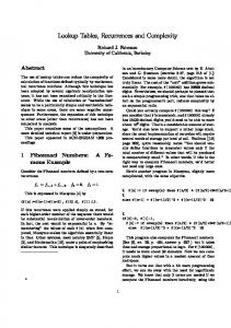
Figure 7.a. Load transient response, Ch-2 load change from 0.3 – 1 A; Ch1-Output voltage top (500mV/div).
VI. REFERENCES
Figure 7.b. Zoomed ac component of the output voltage Ch-1 (50mV/div); Ch2-Load current
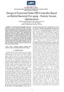
From Figures 7.a. and 7.b. it can be observed that the output voltage variations during transients are smaller than 5% and that the output voltage settles inside the +/-40 mV range in less than 50µs. B. Soft start The presented controller configuration has an additional advantage that it provides a built-in soft start. During startup transient, the error signal is limited to its maximum value and the duty ratio slowly increases from zero toward the steady-state value. Figure 8 shows the output voltage during a start-up transient when the converter is supplied from an input voltage of 6 V.
Figure 8. Output voltage during start-up transient.
V. CONCLUSIONS In this paper we describe design and implementation of a digital PID regulator in a controller based on look-up tables, which results in fast and simple hardware realization. Guidelines for selection of the size of the hardware structure are given and demonstrated on an example of a digitally controlled buck converter operating at 1 MHz switching frequency.
[1] T.W. Martin and S.S. Ang, "Digital Control of Switching Converters,” IEEE Symposium on Industrial Electronics, vol. 2, 1995, pp. 480-484. [2] Y. Duan, H. Jin, "Digital Controller Design for Switch Mode Power Converters,” IEEE Applied Power Electronics Conference, 1999, Vol.2, pp. 480484. [3] B. Patella, A. Prodic, A. Zirger, and D. Maksimovic "High-Frequency Digital Controller IC for DC/DC Converters,” IEEE Applied Power Electronics Conference, 2002. [4] J. Xiao, A.V. Petrechev, S.R. Sanders, “Arhiecture and IC Implementation of a digital VRM controller,” IEEE Power Electronics Specialists Conference 2001, pp. 38-47. [5] A. Prodiċ, D Maksimoviċ “Digital PWM controller and current estimator for a low-power switching converter “, IEEE COMPEL 2000, pp. 123-129. [6] A.M. Schultz, S.B. Leeb, A.H. Mitwalli, D.K. Jackson, G.C. Verghese, “A multirate digital controller for an electric vehicle battery charger”, IEEE Power Electronics Specialists Conference 1996, Vol. 2, pp. 1919-1925. [7] A. Prodic, D. Maksimovic, and R. W. Erickson "Design and Implementation of a Digital PWM Controller for a High-Frequency Switch DC-DC Power Converters,” IEEE IECON 2001. [8] A. V. Peterchev, S. R. Sanders, “Quantization Resolution and Limit-Cycle in Digitally Controlled PWM Converters,” IEEE Power Electronics Specialists Conference, 2001, pp. 465-471. [9] Robert W. Erickson and Dragan Maksimovic, Fundamentals of Power Electronics – Second Edition, Kluwer 2000. [10] G. F. Franklin, J. D. Powell, M. L. Workman, Digital Control of Dynamic Systems – Third Edition, Addison Wesley Longman, Inc 1998, pp. 200-202. [11] B. Patella, "Implementation of a High Frequency, Low-Power Digital Pulse Width Modulation Controller Chip," M.S. Thesis, University of Colorado at Boulder, 2000.