Design of Microcontroller based MultiFunctional Relay for Automated Protective System G. Ramarao, Sateesh K Telagamsetti and V. S. Kale
Abstract-- This paper presents the design and implementation of a microcontroller based multi-functional relay that can protect the equipment against over-current, over-voltage & under voltage. Provision for settings of over voltage, over current and under voltage limits is provided. Simulations are carried out using proteus eight (SP4) platforms and hardware prototype with ATMega328 as core controller is built to validate the operation of the microcontroller as multifunctional numerical relay. Index Terms--Arduino Uno board, ATMega328, faults, micro controller, over current relay, proteus 8 professional).
T
I. INTRODUCTION
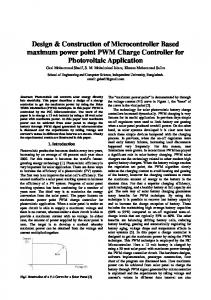
he reliability and security electrical supply is an important factor in modern society. However increasing complexity of power systems makes it difficult for protection operation to achieve these objectives. Nevertheless, numerical relays are able to improve the protection operation significantly. The relays are capable of performing complex processing faster and with higher accuracy [1]. Protection relay is a device which by means of measuring power system quantities (currents and voltages) and processing them through its internal logic, has the capacity to control the operation of a circuit breaker. The internal logic allows the relay to initiate a tripping sequence when anomalous conditions arise within the power system. With regard to their construction three types of relays can be distinguished: electromechanical, static and digital. In electromechanical relays, the actuating force is created by electromagnetic interaction. Static relays are based on analogue electronic components such as diodes, transistors, capacitors, etc. whereas numerical relays have their logic implemented in software and microprocessor technology. Some relay designs combine the static and digital technology. This paper concentrates on the analysis of digital relays. A digital relay consists of the following main parts: microcontroller, analogue input system, digital output system and independent power supply [2]. Figure 1 presents a simplified block diagram of a digital relay. The National Electrical Code defines over current as any current in excess Gandi ramarao ,Sateesh K Telagamsetti, PG students, V S Kale, Associate Professor are with the Department of Electrical Engineering, Visvesvaraya National Institute of Technology ,Nagpur, India. (e-mail)
[email protected],
[email protected],
[email protected].
978-1-4799-4939-7/14/$31.00 ©2014 IEEE
of the rated current of equipment or the ampacity of a conductor. It may result from overload, short circuit, or ground fault. Over current protection devices are used to protect conductors from excessive current flow. etc. If these over voltages are not mitigated, there are chances of insulation failure, so it leads to a line to line fault or line to ground fault. The relay detects the over voltage & operates instantaneously. Overloading of distribution cables and transformers or of cabling within the installation often results in long duration under-voltage problems. Under-voltage can occur when a large load is switched on; over-voltage when the large load is switched off. Under-voltages in power system leads to over loading of system or instability of power grid. When there is a system disturbance and the voltage drops to a pre-selected level for a pre-determined time, then selected loads are shed by under voltage relay [3]. Proteus 8 is software for electronic circuit simulation, microprocessor simulation, schematic capture, and printed circuit board (PCB) design. It is developed by Labcenter Electronics. There are many system components in the software. Whether your requirement is the rapid entry of complex design for simulation & PCB layout, or the creation of attractive Schematic for publication, ISIS is the right tool for the job Product Features [4]. The ATmega 328 microcontroller is a computer on a chip or a single chip computer. High Performance, LowPowerAVR 8Bit Microcontroller, advanced RISC Architecture, High Endurance Non-volatile Memory Segments, Peripheral Features, I/O and Packages, Operating Voltage, Low Power Consumption, Another term is Embedded Microcontroller, which tells that its support circuits are often built into or embedded in the devices for control [5]. II. PROPOSED DIGITAL RELAY The signals from the current sensors and voltage sensors cannot be sampled directly and converted to the digital form. This is to make sure that the signal does not contain frequency components having a frequency greater than one half of the sampling frequency. This limit is enforced by the Shannon's sampling theorem. Therefore, the signals are first passed through a low-pass filter, which has to be an analogue type of filter, because digital processing can only take place after the frequency spectrum of the signal is properly shaped. Next, the analogue signal is sampled and held constant during the time the value is converted to digital form. The sample and hold circuit is an absolute must. The range of frequencies that can be handled by the analogue-to-digital converter without the
sample and hold (S/H) circuit is extremely low. The sample and hold circuit and the ADC work under the control of the microprocessor and communicate with it with the help of control signals such as the end-of conversion signal issued by the ADC. The ADC passes on the digital representation of the instantaneous value of the signal to the microprocessor via an input port. The output of the ADC is 8 bits. The wider the output of the ADC, the greater its resolution. The incoming digital values from the ADC are stored in the RAM of the microcontroller and processed by the relay software in accordance with an underlying relaying algorithm. The microprocessor issues the trip signal on one of the bits of its output port which is then suitably processed so as to make it compatible with the trip coil of the CB, whenever the abnormal conditions occur then buzzer makes sound [6].
excess current flows in the line current sensor sense that current from the line, this sensed current is further modified by sending through the AAF, S/H circuit and ADC. But arduino knows the value equalant to binary that will be given by the ADC. In arduino, program should be written before performing the operation. Then arduino uno board can compare the actual value to set value which is already mentioned in the program. If there is exceed the current, then aruduino will give the trip signal to the relay through optocoupler, relay driver circuit and electromagnetic switch. Same procedure will be applicable for the voltage also. In this paper, under voltages and over voltages are taken into account. Voltage should in the limits, “Vmin