J. Bangladesh Electron. 14 (1-2); 101-105, 2014
Design of Microcontroller Based Generator Protection Scheme 1
Md. Rokonuzzaman and 2Mohammed Hossam-E-Haider Electrical, Electronic and Communication Engineering Department Military Institute of Science and Technology, Dhaka, Bangladesh
[email protected] and
[email protected]
Abstract—Electricity generation is the heart of power system and alternator is widely used for electricity generation. Therefore the protection of alternator is very important for smooth operation of overall power system network. The fault detection and isolation of the faulty section or apparatus from the system is done by using protective devices like fuses or relays in conjunction with the circuit breaker. The differential relay acts as main protection whereas the over current and earth fault relays act as backup protection for the alternator. The backup protection actuates only if the main protection fails. The fault clearance greatly depends on the actuating quantity and operating time of the relay which need to be coordinated with the protective system requirement. The static relay has faster and reliable operation than those of the conventional electromechanical relay. In this paper the microcontroller based protection scheme is designed for alternator protection. The triac performs the task of relay contact whereas the optocoupler provides electrical isolation between input and output sections of this protective scheme. The microcontroller ensures faster and accurate switching of the triac according to the programming logic. Keywords— Alternator Fault Protection, Fault Detection, Main protection, Back up Protection, Microcontroller Based Protection. I. INTRODUCTION The volume of infrastructure of electrical power system is increasing day by day due to installation of new generation plants along with expansion of transmission and distribution network. Therefore system protection devices need to be more sophisticated than before for uninterrupted operation of the overall power system network [1]. The reliability and accuracy are the main concern in designing system protection. The fuse and relay are most commonly used protective devices in electrical power system. For the last few decades the electromechanical type relay dominated in power system [2]. Still in this twenty first century, many power system of the developing countries still dependant on electromechanical relay for system protection [1], [2]. Though this type of relay is relatively cheaper than the static relay, the faster response time and reliable operation makes the static relay more suitable for system protection of modern power system network [3]. For remote, reliable and uninterrupted operation, the power system network is managed by SCADA (Supervisory Control and Data Acquisition System), EMS (Energy Management System) and AGC (Automatic Generation Control Systems) [1]. The static relay based programmable protection and control 1
J. Bangladesh Electron. 14 (1-2); 101-105, 2014 systems are installed in different locations of power system which are linked by means of data transmission channels such as power line carrier (PLC), microwave and optical fiber cables. The static relay provides both main and backup protection as well performs auto reclosing sequence, sequential tripping, load shedding, remote signaling and others [2], [3]. The use of microprocessor/microcontroller and semiconductor switching device helps in perfect system coordination for protection of power system. The compactness and accuracy of operation make the static relay more advantageous to use than those of the electromechanical relay for fault detection [4], [5]. Due to vastness of modern power system, fast and reliable operation of system protection is required. The static relays are replacing the electromechanical relays for more reliable protection. The advantages of static relays are low power consumption which provides less burden on CT and PT, reduced resetting time and overshoots, no moving contacts, faster operation, and simplified testing and servicing [5], [6]. II. RELAY AND GENERATOR PROTECTION When a short circuit occurs in an electrical system then the impedance of the system reduces which thereby increases the fault current [2]. Generally the magnitude of the fault current is more than the rated current of any system. The relay senses the fault current and trips the corresponding protection system [3]. The relay picks up when the magnitude of the system current exceeds the pickup value of the relay. The fig. 1 shows the basic protection circuit diagram of relay operated protection scheme.
Fig.1 Basic Protection Scheme A. Main Protection of Generator The primary protection from phase to phase faults is provided by a differential relay. The differential relay detects three-phase fault, double phase to ground fault and single phase to ground fault [3]. However due to low impedance grounding of the generator sometimes double phase to ground fault can also be detected. Moreover turn to turn fault in the same phase cannot be detected since the current entering and leaving the winding becomes same [4]. The differential protection is used for protection of the generator against phase to earth and phase to phase fault. This protection is based on the merz price circulating current principle [5]. In this type of protection, currents at two ends of the protection system are compared. Under normal conditions, currents at two ends remain same. But when the fault occurs, current at one end differs from the current at the other end and this difference of current flows through the relay operating coil [7]. The relay then closes its contacts and makes the circuit breaker to trip and thus isolate 2
J. Bangladesh Electron. 14 (1-2); 101-105, 2014 the faulty section. The differential protection mainly depends on merz prize circulating current principal where CTs of both ends of the alternator measures current [6]. Under balanced condition there is no difference of currents of CTs at both ends and the relay doesn’t actuate. The relay actuates when there is a difference in currents occurs due to system unbalance. B. Back up Protection of Generator: The backup protection for phase to phase and three phase faults in the generator is provided by overcurrent and earth fault relay, shows in Fig. 2. There exists a time coordination between relays of main and back up protection within the protective zone. The protection zone depends on the relay reach, CT placement and directional setting [3], [5]. The combined phase and neutral over-current relays are used for short circuit and over- current protection. The over-current relays are available as either a single pole or a three pole unit having an independently adjustable current sensing circuit driving a common adjustable timing element. One of the main causes of ground fault insulation failure. The zero sequence impedance of a generator is usually lower than the positive or negative sequence and hence for a solidly grounded generator, the single phase to ground fault current is greater than the three phase fault current. To limit the ground fault current, generators are usually grounded through impedance. The highsensitivity ground fault protection operates independently in order to detect ground fault since the ground fault current is relatively smaller than the phase fault current [4].
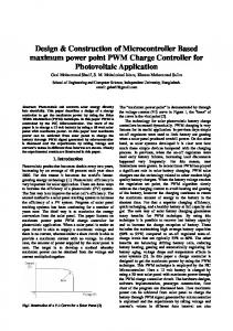
Fig. 2 Over current and earth fault protection of Alternator. III. DESIGNED PROTECTION SCHEME AND ITS OPERATION There are four blocks in the designed scheme. The block diagram of the designed protection scheme is shown in the fig. 3. The CTs (Current Transformer), bridge rectifiers, voltage regulator, capacitors and resistors are in the input section. The microcontroller is in the controlling section which compares the equivalent voltage of fault current with the reference value. The switching section has optocoupler, triac and resistor. The triac is operated according to the logical operation of microcontroller. The trip coil and dc battery is in the output section. The circuit breaker for alternator protection trips when the trip coil is energized due to operation of the triac.
3
J. Bangladesh Electron. 14 (1-2); 101-105, 2014
Fig. 3 Block Diagram of the Design Protection Scheme The complete circuit diagram of the protective system is shown in fig. 4. The fault current of the alternator is sensed by CT. For differential protection, the secondary windings of CTs are star connected. Since the microcontroller cannot sense current, therefore current is converted to equivalent voltage by using resistor. Similarly for over-current and earth fault protection, the fault current from CT is converted to equivalent voltage for logical operation of microcontroller. The resistors across CTs are selected in such a way that the fault current is converted to 5 V DC by using bridge rectifiers (BR1, BR2 and BR3) and capacitors.
Fig. 4 Circuit Diagram of the Protection The GBPC3508 type bridge rectifiers are used which has maximum current capacity of 35 A. For constant reference voltage of 5 V, IC 7805 is used which acts as voltage regulator. The microcontroller, ATmega8 is used for controlling the overall operation of the protection scheme. The respective equivalent DC voltage of the fault current from CTs of differential, over- current and earth fault protection is compared with the reference voltage in the microcontroller. These voltages are connected to pins PC0 –
4
J. Bangladesh Electron. 14 (1-2); 101-105, 2014 PC3 of the Atmega8 [8]. The microcontroller gives outputs in pins PB0 – PB2 according to the controlling logic in its program [8]. The outputs of the microcontroller initiate three optocouplers (OC1 - OC3). The MOC3023 type optocouplers are used for this design which ensures isolation between input and output [9]. The optocouplers provide trigger pluses to triacs, U1 – U3 according to the outputs of microcontroller. The Q5025R5 type triac is used for the design which has maximum voltage and current handling capacity of 600 V and 25 A respectively. The natural commutation is used for tuning off the triacs so that two triacs cannot be turned on at the same time. The triacs are connected in series with the trip coil of the circuit breaker and battery. When a particular triac is turned on, the trip coil is energized by the DC voltage of the battery. In this design, the triac replaces the relay contact of the conventional protection scheme. C. Logical Operation of AVR The logical diagram for operation of the protection scheme is shown in the fig. 5.
Fig. 5 Logical Diagram of the Protection Scheme The microcontroller compares the equivalent voltage of the fault current with the reference voltage and generates outputs accordingly. When the equivalent voltage is greater than the reference voltage then the triac is turned on and thereby the trip coil of the circuit breaker is energized. The triac remains off when the equivalent voltage is either equal or smaller than the reference voltage. When any CT of the differential, over-current and earth fault protection senses the fault current in the alternator then the corresponding triac is trigged and energizes the trip coil of the circuit breaker. Thereby the circuit breaker is tripped and protects the alternator.
5
J. Bangladesh Electron. 14 (1-2); 101-105, 2014 IV. CONCLUSION Proper selection and coordination among protection schemes of protective zones are essential for electrical system protection. The reliable and uninterrupted supply of electricity can only be ensured by faster detection and clearance of system fault. The alternator is the heart of electricity generation therefore reliable protection of alternator is required. The use of microprocessor or microcontroller in the static relay initiates faster and reliable operation. The proposed design of protection scheme uses microcontroller as controlling device and triac as switching device. The semiconductor switching device is durable and faster in operation than the conventional relay contacts. Moreover, the overall operation of the proposed protection scheme can be changed according to the programming logic of the microcontroller. REFERENCES [1]
[2]
[3] [4] [5] [6] [7] [8 [9]
M. Adamiak, D. Dhurba, J. Gardell, S. Patel and D. Viers, ―Performance Assessment of a New Digital Subsystem for Generator Protection‖, in Proc. 20th Annual Western Protective Relay Conference, 1993, Spokane, WA, pp.19-21. D. Finney, B. Kasztenny and M. Adamiak, ―Generator Protection Needs in a DG Environment‖, in Proc. Power Systems Conference 2002: Impact of Distributed Generation, March 13-15, 2002, Clemson University, Clemson, SC. S. S. Rao, Switchgear Protection and Power Systems, 12th edition, Khanna Publishers, India, 2007. L. L. Grigsby, Power System Stability and Control, 2nd edition, CRC Press, USA, 2008. M. E. El-Hawary, Electrical Energy Systems, 2nd edition, CRC Press, USA, 2009. E. W. Kimbark, Power System Stability (Power Circuit Breaker and Protective Relays), 3rd edition, John Wiley and Sons Inc. Publication, USA, 2007. J. L. Blackburn and T. J. Domin, Protective Relaying Principles and Applications, 3rd edition, CRC Press, USA, 2008. AVR Enhanced RISC Microcontrollers Data Book, ATMEL Corporation, USA, May 1996. M H Rashid, Power Electronics Handbook, San Diego, California 92101-4495, USA: A Harcourt Science and Technology Company, 2001.
6