Journal of Multidisciplinary Engineering Science and Technology (JMEST) ISSN: 3159-0040 Vol. 2 Issue 4, April - 2015
Design, Simulation and Pilot Implementation of a Campus Area Network That Supports Teleconferencing Eze P.U Dept. of Computer Science, The University of Sheffield, UK
[email protected],
Diala U.H. Dept. of Automatic Control and System Engineering The University of Sheffield, UK.
[email protected],
Ndukwe C.I. Dept. of Electrical/Electronic Engineering University of Leeds, UK
[email protected]
Abstract—The need for a reliable communication network within a university campus is not a luxury; it is a necessity. Currently, no such network exists at the Federal University of Technology Owerri (FUTO) in Nigeria. This project addresses the situation by using a top-down approach to design a campus network of adequate network performance to support bandwidth-intensive applications such as teleconferencing. The campus network design, carried out after analysis of the user and technical network requirements, was partitioned into logical and physical domains. Network simulation was carried out with the aid of the Cisco Packet Tracer 5.3 software. SIP-based client software, FUTO Messenger, was developed to run on the network. The software supports text, voice and video chats. A prototype network system was implemented to test the network design and also to verify the functionality of the developed software. The system had 6 workstations comprising 2 teleconferencing PCs, 2 non-teleconferencing PCs, a Wireless Access Point and a SIP Server. Successful ping tests were carried out. Chat, audio and video sessions were set up successfully with optimal transmission quality.
explanations. Organizations that implement thoughtfully-designed, well-implementedand effective teleconferencing solutions realize significant cost savings and productivity gains throughout their enterprise.
Keywords—Teleconference, SIP, CAN,Wireless
The network architects in [3] designed a largescale WLAN (Wireless Local Area Network) to provide high-speed wireless service on the campus. The WLAN network covered 65 buildings and was built on the University’s wired network infrastructure, which provided 10Mbps, 100Mbps and Gigabit Ethernet service to the desktop. To provide high speed wireless service to the campus, they installed WLAN equipment conforming to the IEEE 802.11b standard. The WLAN was structured in such a way that it connected to the campus network through an IEEE 802.3 backbone networks on campus through a dedicated switch in the central campus network facility. Each AP (Access Point) was connected to an IEEE 802.3 10Base-T hub in a building’s remote wiring closet near the AP. These hubs, in turn, were connected to a switch in the building’s main distribution wiring closet, which is in turn connected to a switch in the University’s central network facility. This central switch’s connection to a router in the central network facility is the link that connects the
I. INTRODUCTION Effective communication is a vital component for every corporate organization in the world today. Computer networks of various scales (LAN - Local Area Network, CAN - Campus Area Network, MAN Metropolitan Area Network, WAN - Wide Area Network and others) and topologies (hierarchical, star, mesh, bus, ring and others) are being designed to solve the specific needs of every organization. A Campus Area Network is a mid-range networking solution for a university or corporate campus. Computer networking serves as a platform for various applications to be run and shared by various users. Teleconferencing is a typical application that can function over the network. Video makes important messages easier to understand, enables quicker decisions, builds high trust, makes negotiating easier, reduces confusion and misunderstanding, makes people more accountable, and is better for detailed
II.
REVIEW OF RELATED WORKS
Various Campus networks have been designed to meet a set of specific requirements including topology, network modes etc. The IT team in [1] proposed a network upgrade design for JWD hospital. The logical design employs the Cisco SAFE Architecture. This architecture uses a modular approach. The modularity built into the architecture allows flexibility in network design and facilitates implementation and troubleshooting. However, there was no integration of teleconferencing infrastructure in the design. A top-down network design process was used in [2] to upgrade the existing network in the University. He employed a hierarchical topology in his design and solved the poor network performance problem by providing a high availability backbone in the network, a redundant link, fast link failure detection and a failover inside the routing protocol.
www.jmest.org JMESTN42350528
550
Journal of Multidisciplinary Engineering Science and Technology (JMEST) ISSN: 3159-0040 Vol. 2 Issue 4, April - 2015
wireless backbone to the remainder of the campus data network. A.E.A. Kareem [4] explored the viability of deploying video conferencing systems in a Nigerian tertiary institution. The software designed for the network used the JavaScript TM language. He divided the program into three modules. The first module of the program captured the video and audio signals and stored them in a file for playback. The signals were stored in the .AVI file format. It was designed to have an interface which could stop or continue to capture as required. In the second module, the captured video and audio signals were being transmitted from the lead sight to the receiving end. In this module, the IP (Internet Protocol) address and the port number of the receiving end. This enabled easy communication between the lead sight and the receiving end. The transmission was done in a fraction of microseconds leading to a real time synchronous process. In the last module, coordination was handled. The transmitted streams were received at the destination and the address of the lead sight was specified so that the package would not get lost during transmission. A.
Networking Infrastructure
Basic networking infrastructural devices include: Router: A router is a networking software or hardware device that forwards packets of data across networks. It interconnects two or more networks together Ethernet switch: A switch is a device that allows a PC to be connected to a network. It directs information around the network, facilitating communication between all connected devices. A switch supports full duplex it isolates each port into its collision domain. WAP (Wireless Access Point): This is a specially configured node on a Wireless LAN. It acts as a central transmitter and receiver of WLAN radio signals. B.
Teleconferencing Infrastructure
Endpoints: The endpoints of a video architecture are the hardware components that process bi-directional audio, video and data streams. Endpoints interface to the users. Gatekeeper (Server): A gatekeeper enables central management and control services. When a gatekeeper exists, all endpoints (terminals, gateways and MCUs) must be registered with it. Registered endpoints' control messages are routed through the gatekeeper. A management zone consists of a gatekeeper and the endpoints it administers. A gatekeeper provides several services to all endpoints in its zone. MCU (Multi-Point Control Unit): MCUs enable video conferences between three or more persons. Different network environments require different MCU resources.
In distributed network environments where network resources are not centralized, multiple (often smaller) MCUs localize the resource and “no single point of failure” redundancy. The MCU could be purely software or a combination of hardware and software. In centralized network environments, centralized bridging management is essential and can be achieved with a robust MCU capable of managing large quantities of video traffic and scalable to meet the most demanding needs. The MCU manages all call setup control functions and conference resources as well as the opening and closing of media streams. The MCU processes audio and video media streams only. Gateway: A gateway allows different network protocols to communicate by translating one protocol to another. The gateway could be hardware or software based. The gateway negotiates video and audio calls between parties, defines access protocols, and provides operational and security management for video calls. III FUTO CAMPUS NETWORK TECHNICAL REQUIREMENTS AND ANALYSIS Scalability -Network scalability will be achieved by the use of hierarchical network topology and optimal Network Management design. Availability - The use of redundant components (multiple switches running STP – Spanning Tree Protocol) will ensure availability in the FUTO Campus network. Adequate Network Performance - Common performance factors include Bandwidth, Throughput, Delay and Delay variation. Optimum network performance will be sustained by the following: Optical fiber media will be used as network backbone, 802.11n WAPs will provide 54Mbps data rates for non-teleconferencing users and Teleconferencing endpoints will be provided with dedicated 100Mbps CAT-5 cables. Quality Of Service (QoS) - With the aid of QoSsupported switches and network VLANs, transmission quality and service availability of a network will be sustained adequately. Security - Software-based firewalls will be implemented across the network, The Wireless Access Points will use WPA-2 Security standard. Physical Security will be achieved by placing network components in a secure room. Remote access to network devices will be de-activated. A. Futo Network Design Methodology The Network design is divided into two domains, namely:
Logical design
Physical design
www.jmest.org JMESTN42350528
551
Journal of Multidisciplinary Engineering Science and Technology (JMEST) ISSN: 3159-0040 Vol. 2 Issue 4, April - 2015
1) Logical Design: A hierarchical design model has been employed in the logical design of the FUTO campus network as in Figure 1. Each layer provides specific functions that define its role within the overall network. By separating the various functions that exist on a network, the network design becomes modular which facilitates scalability and performance. The hierarchical design model is typically broken into three layers: Core, Distribution and Access layers. a) Access Layer: FUTO Access layer interfaces with end devices such as PCs, printers and IP phones to provide network access to the rest of the network. After an extensive survey of all the buildings in FUTO, the WAP (Wireless Access Point) was deemed the most feasible access layer device due to the Absence of conduit wired UTP cables and provisions for Ethernet wall jacks. The WAP connects to the building distribution switches through a hub (unmanaged switch). It is envisaged that the various departments and administrative offices in the school will make up the Access layer in the FUTO CAN. Thus, each office was allotted one Wireless Access Point (WAP) in the design.
set to client and all belong to the FUTO VTP domain. The distribution layer wiring closets for the FUTO campus area network will be situated in designated rooms in each school or administrative complex. Each school and major building will have a switch. c) Core Layer: FUTO Core layer is critical for interconnectivity between distribution layer devices. It interconnects the Access and Distribution modules with the data center Network Management and edge modules. Due to the importance of this layer, it has been designed to be highly available and have redundant connections. The Core switch also serves as a distribution switch for certain buildings. The Core layer devices for FUTO campus area network will be domiciled at a designated room in ICT center. The core layer is made up of Layer-3 switches. The VTP mode of the core switch is set to Server ensuring that all VLANs are registered only on it. d) Network Management Design: A Network Management System running SNMP (Simple Network Management Protocol) will be used to display management data. It will also be used to monitor, control and communicate with managed devices within FUTO CAN. The Network Management system will be located at ICT center and its agents will be installed on all the network nodes. Network Management processes to be carried out on FUTO Campus Network include:
Fig 1: FUTO logical network design In designing the WLAN, the BSS (Basic Service Set) infrastructure connection model (connections between one or more clients and a single WAP) was employed for departments and ESS (Extended Service Set) was employed for Administrative blocks. All WAPs (Wireless Access Points) will use WPA-2 (Wireless Protected Access version 2) encryption, 802.11n wireless standard, 20MHz channels in the 5GHz frequency band. b) Distribution Layer: FUTO Distribution layer aggregates the data received from the access layer WAPs before it is transmitted to the Core layer for routing to its final destination. The distribution layer controls the flow of network traffic using policies and delineates broadcast domains by performing routing functions between Virtual LANs (VLANs) defined at the access layer. High performance switches are used in the distribution layer design for high availability and redundancy to ensure reliability. The VTP (VLAN Trunking Protocol) mode of all distribution switches is
Fault management
Configuration management
Accounting management
Performance management
Security management
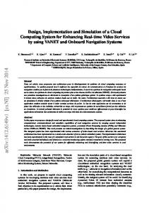
e) FUTO Teleconferencing Network Design: A campus single-zone deployment model has been implemented for this design as in Figure 3.2. It consists of: A Server supporting SIP (Session Initiation Protocol). All the video endpoints are registered on the gatekeeper. Telepresence (Teleconferencing) endpoints which bypass the wireless network connection and are connected directly to an unmanaged switch (referred to as a hub) to enhance QoS and bandwidth availability for teleconferencing.
www.jmest.org JMESTN42350528
552
Journal of Multidisciplinary Engineering Science and Technology (JMEST) ISSN: 3159-0040 Vol. 2 Issue 4, April - 2015
MEE
HUB/WAP
MEE
PET
HUB/WAP
PET
BCH
BCH
REGISTRAR
HUB/WAP SWITCH/ HUB/WAP HUB/WAP
SENATE
-----
LIBRARY
HUB/WAP
---
UNKNOWN
HUB/WAP
STA; POT
MEDICAL
HUB/WAP
---
FUTO CONSULTS
HUB/WAP
---
PGD
HUB/WAP
---
CCE
HUB/WAP
---
B
Network Cabling Guidelines
Optical fiber will be used as the backbone of FUTO campus network. Fiber was selected due to the following reasons: Fig 2: Campus single zone network mode
Low signal loss and high bandwidth
2)
Immunity to electromagnetic interference
Light weight
Physical Design
WAP used in design: Cisco Aironet 1262 802.11n Distribution layer switch used in design: Cisco Catalyst 3560 Core layer switch used in design: Cisco Catalyst 3750 *HUB= Unmanaged switch TABLE I: Physical location and switch allocation to all Departments and Administrative offices LOCATION (BUILDING) ICT (CORE LAYER) SEET
NETWORK DEVICES SWITCH/ HUB/WAP SWITCH HUB/WAP
DEPARTMENTS --EEE; PTE; AGE; CIE; FST, MME, DEAN (SEET)
SOSC
SWITCH/ HUB/WAP
ICH; IMB; CSC; BTC; IPH; GSC; SLT; MTH; DEAN (SOSC); DEAN (STUDENT AFFAIRS)
ETF
SWITCH/ HUB/WAP
FAT; AST; FWT; AEX; AEC
SOHT
SWITCH/ HUB/WAP
PHT, DEAN (SOHT)
SMAT
HUB/WAP
DEAN (SMAT)
DGS
SWITCH/ HUB/WAP
IMT; PST
NMAB
SWITCH/ HUB/WAP
TMT; MMT
MGT TECH
SWITCH/ HUB/WAP
FMT; PMT
SWITCH/ HUB/WAP HUB/WAP
EVT; BDT; QST; SVG; URP; ARC; DEAN (SOET) CHE
SOET CHE
The direct burial underground installation method will be used in the interconnection of border network devices. The cables will be buried in trenches. Steel armored outdoor fiber cables will be used. At the Distribution layer, Copper Shielded Twisted Pair rated for Category 5 or 5e will be used as transmission media. C
Teleconferencing Software Documentation
1) FUTO Messenger: The FUTO Messenger is the client software developed for the FUTO Campus Network. It is written in C# in .NET Framework and compatible with OfficeSIP Communications Server. FUTO Messenger provides instant communications across the network. It supports text, voice and video chats. a) FUTO Messenger Architecture: FUTO Messenger is based on UCCAPI (Unified Communications Client Application Programming Interface), a SIP-based application framework for building and deploying real-time communications client applications against a SIP registrar or proxy Server. Standard features of the UCCAPI include IM (Instant Messaging), voice calling, video chatting, contact managing and presence tracking. Unified Communications Client API encapsulates two major functional features in real-time communications: Signaling and Media handling. The signaling and media handling between an application and the underlying SIP stack and media management are separated over the RTP (Real-time Transport Protocol) stack. Figure 3.3 below illustrates the Unified Communications Client API application architecture.
www.jmest.org JMESTN42350528
553
Journal of Multidisciplinary Engineering Science and Technology (JMEST) ISSN: 3159-0040 Vol. 2 Issue 4, April - 2015
Initializes the application framework of Unified Communications Client API by creating a UccPlatform class and calling the Initialize method on the IUccPlatform interface
Registers a user with the Server
Subscribes to receive categories sent in-band by the Server such as configuration information, contact lists and self-presence information. These categories are continuously monitored and updated as they are sent by the Server Establishes and maintains media communications sessions for application sharing, IM, Audio/Video (AV) calls between a computer and another computer Manages local devices that can be used in a media session
Fig 3: UCCAPI FUTO Messenger application architecture The SIP stack handles signaling following the standard SIP. It is responsible for carrying out all lowlevel SIP operations, such as sending a session request, dispatching and receiving provisional responses, and accepting, forwarding, or rejecting an invitation. These operations are necessary for establishing communications and conference sessions where participants can communicate and collaborate with each other. The Media Manager is responsible for the low-level media management functions including establishing communication channels to transmit audio, video, or other application data between endpoints. Unified Communications Client API objects can be logically grouped into the following feature-based categories: Platform Object: The entry point to the Unified Communications Client API functionalities. Endpoint Object: The object representation of the user in real-time communications and collaborations. Session Objects: Encapsulation of signaling and collaboration sessions, including instant messaging (IM), voice, video, application-sharing and conference. Publication and Subscription Objects: Encapsulation of the general framework for publishing and subscribing to data or information. Device Management Objects: Encapsulation of the management functionalities for local devices to render media.
Publishes data that is represented by generic category instances and subscribes to the notifications of updates of such data Manages contacts, publishing and subscribing to contacts-related category instances Manages presence, publishing and subscribing to presence-related category instances Chooses an appropriate media connectivity server to ensure media delivery across firewalls if the client connects from outside the enterprise network b) OFFICESIP Server: OfficeSIP Server software is deployed to provide server functionality. OfficeSIP Server enables voice calling in FUTO Messenger and similar software-based open protocol SIP clients. It is designed for IM, enabling VoIP communications in SIP-compliant software and hardware clients. The SIP server provides centralized information and enablement services. Basic functions of the SIP server include: Authenticates registers and stores users’ logical identities and physical entities (IP addresses) of the communication devices on the registrar database. User devices are identified by their Uniform Resource Identifiers (URIs) Accepts, stores and distributes presence information that allows users to see the availability of people Sets up and tears down communication sessions
Media Connectivity Objects: Encapsulation of the management functionality for enabling media transmission across firewalls.
Keeps track of users and their locations during roaming by accurately mapping a logical SIP address to physical IP address using the registrar database so that communication sessions can be properly established and maintained
The following list summarizes the basic application tasks that FUTO Messenger performs:
IV NETWORK VERIFICATION
DESIGN
SIMULATION
AND
www.jmest.org JMESTN42350528
554
Journal of Multidisciplinary Engineering Science and Technology (JMEST) ISSN: 3159-0040 Vol. 2 Issue 4, April - 2015
This was achieved using Cisco Packet Tracer software v5.3. Three departments: EEE, AGE and ICH were employed in the simulation. EEE and AGE are both situated in SEET building and as such use the same distribution switch while ICH department located at SOSC building utilizes a different switch. Ping tests were successfully carried out.
Figure 5 above is the ‘Login As’ windows for FUTO Videophone. Users input their username and password together with their sign-in address.
A Requirements For FUTO Prototype System Implementation The following hardware is needed to complete the development and in-house deployment of the system: i. Two laptop systems teleconferencing client software ii.
running
the
Two non-teleconferencing laptop systems
iii. A laptop which serves WAP and network bridge iv.
A server system running the SIP Server
v.
An unmanaged switch
vi.
CAT-5e cables
Fig 6: FUTO Messenger
OfficeSIP Server
192.168.111.1
192.168.100.22 Network Bridge WAP
Fig 7: FUTO Messenger - Chat
192.168.111.4 192.168.111.7 192.168.100.11 192.168.100.3 FUTO Messenger Client
The FUTO Messenger window in Figure 8 below allows users IM sessions (as in Figure 9) as well as Audio-Video chats (as in Figure 10) with other online users.
FUTO Messenger Client Endpoint
Endpoint
Fig 4: Logical setup of prototype teleconferencing system B
Teleconferencing Software Results
Fig 8: FUTO Videophone – Audio Video chat Fig 5: FUTO Videophone – Login As www.jmest.org JMESTN42350528
555
Journal of Multidisciplinary Engineering Science and Technology (JMEST) ISSN: 3159-0040 Vol. 2 Issue 4, April - 2015
Figure 8 shows the received and transmitted visual signals after a video call has been successfully setup between users. 1)
OFFICESIP Server Screen Captures:
hierarchical design, which has been adequately provided for. Finally, we recommend that an IT department should be established to manage FUTO Campus Area Network effectively. VI
REFERENCES
[1] M. Rosalie et al, “JWD Network Upgrade”. Available:http://joseph.schuesslersounds.com/ Teaching/Tarleton/CIS504/SampleProjects/J WD%20Network%20Upgrade.pdf [Accessed: April 2, 2013]. [2] B. Mulyawan, “Campus Network Design And Implementation Using Top Down Approach: A Case Study Tarumanagara University” [Online]. Available: http://eprints.undip.ac.id/36065/1/bagus_muly awan.pdf [Accessed: April 6, 2013].
Fig 9: The OfficeSIP server showing registered users and their presence status
[3]H. Alex, “Large Scale Wireless LAN design”, IEEE Communications Magazine, November 2001. [4]A.E.A. Kareem, “Implementing a Desktop VideoConferencing Technology for Effective Teaching andLearning”, Pacific Journal of Science and Technology,2009.
Fig 10: User registration screen To add a user to the server database, click on the ‘Add’ button in order to create a user account. V
CONCLUSION AND RECOMMENDATIONS
The implementation of this design will reduce operating costs and strongly improve communications. This will enable faster and more informed decision making in our tertiary institution. This work builds on the existing systems in [2] and [4] while integrating teleconferencing infrastructure. The SIP software developed facilitates Video conferencing, Audio conferencing, IM (Instant Messaging) and file collaborations across the network. We recommend that Network design should be updated regularly to account for new buildings. This is easily achievable as network scalability using the www.jmest.org JMESTN42350528
556