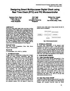
cleared and latched by the register following it. In a pipelined system, pipeline stage with the longest computation time dictates clock-cycle time for the entire.
Designing Pipelined Systems with a Clock Period Approaching Pipeline Register Delay Suryanarayana B. Tatapudi and José G. Delgado-Frias
I. INTRODUCTION In digital system design, pipelining is implemented to achieve higher throughput. In a pipelined system, switching events must occur in well defined order and at precise time for proper functioning of the system. Clock is a globally distributed signal which controls these switching events. In any digital system, of all data and control signals, clock signal is the one with the largest fan-out, fastest switching rate and is distributed throughout the chip. Since all data synchronization in a pipelined system is based on clock signal, clock uncertainties (skew, jitter) must be controlled for proper functioning of the system. In recent years due to technology scaling, CMOS devices are becoming fast, reducing the computation times. To achieve higher operational (clock) frequencies digital designers are using ultra-thin super-pipelines, as a result of which the load on the clock distribution is increasing and it is becoming extremely difficult to distribute a clean gigahertz frequency clock signal [1], [2]. Increasing portion of clock period is also being spent in countering clock uncertainties. Thus the useful portion of clock period available for computation is decreasing. Significant research is being done to counter such uncertainties by design optimization and technology improvements [3], [4]. Considerable effort has been put into studying various clock distribution schemes like the resistance-capacitance matched tree, the grid, the tree network, and the serpentine. However,
Output data
Logic Stage N
Register N+1
Register N
Logic Stage 2
Register 3
Logic Stage 1
Register 2
Register 1
Abstract—A novel mesochronous pipelining scheme is described in this paper. The clock period in the proposed pipeline scheme is determined by the pipeline stage with largest difference between its minimum and maximum delays. This is a significant performance gain compared to conventional pipeline scheme where clock period is determined by stage with the maximum delay. Also, in the proposed scheme the number of pipeline stages and pipeline registers is small and the clock distribution scheme is simpler. An 8× ×8-bit carry-save adder multiplier has been implemented in mesochronous pipeline architecture using modest TSMC 180nm. The multiplier architecture and simulation results are described in detail in this paper. The pipelined multiplier is able to operate on a clock period of 350ps (2.86GHz), with fewer pipeline stages and pipeline registers.
Input data
School of Electrical Engineering and Computer Science Washington State University, Pullman, WA 99164–2752 Email: {statapud, jdelgado}@eecs.wsu.edu
Clock
Fig. 1. N stage pipelined system.
the gain from using these schemes is small. Also it is increasingly becoming difficult to study them due to parasitic (resistance, capacitance and inductance) modeling errors. With shrinking feature sizes, the interconnecting wires are becoming thin, long, and highly resistive. With high speed signals having fast rise/fall times running on thin long wires, the inductive component of wire parasitic is gaining significance [5]. In future, to derive significant performance gains, improved clocking methodology and clock distribution are needed. In this paper we present a pipeline scheme called Mesochronous pipeline (MPP) to achieve higher operational speeds in digital systems. Also this architecture greatly reduces the complexity of clock distribution network. The organization of the paper is as follows. In Section II, the mesochronous pipelining concept is introduced. In Section III and IV, we discuss the implementation and performance of an 8-bit multiplier in the MPP architecture. Finally in Section V, some concluding remarks are presented. II. THE PROPOSED PIPELINE SCHEME In a conventional pipeline scheme, a digital system is divided into small sub-systems called pipeline stages separated by pipeline registers. The schematic of an N-stage pipelined system is shown in Fig. 1. In a pipelined system, pipeline stages operate on different data waves simultaneously and each stage on only one data wave at any given time. Pipeline registers synchronize data movement from one stage to next with reference clock edge. New data is admitted into a stage only after data in that stage has been cleared and latched by the register following it. In a pipelined system, pipeline stage with the longest computation time dictates clock-cycle time for the entire system.
Tclkconv ≥ Dmax + DR + ts + ∆clk
Register
Logic
Register
Logic
Register
Logic
Register
Logic
Register
Logic
Register
Logic
Register
Equation (1) defines the clock cycle time for a conventional pipeline scheme. (1)
Clock
such a partition is super-pipelines. By partitioning the pipeline stages, stage propagation delay may become comparable to the register delays. The MPP scheme modifies the conventional pipeline scheme to achieve improved performance gains. In the proposed scheme, a logic block operates on more than one data wave simultaneously, which means multiple data waves can exist in a stage at any given time. Clock signal path is also modified in this scheme; clock travels with data. The schematic of this scheme is shown in Fig. 3. Clock signal path includes delay elements (∆Si) which emulate the delay experienced by data in pipeline stages. In this pipelining scheme, higher clock frequencies are possible, complexity of clock distribution is greatly reduced and influence of clock uncertainties is mitigated. The clock period of this system is determined by stage with the largest delay difference and safe time required before a new data wave is admitted into this stage. Delay difference of a stage is the difference between its minimum and maximum propagation delay. The fundamental circuit limitations determine the safe time to separate any two adjacent data waves. Using mathematical analysis [7] the equation for clock period can be written for the MPP scheme as Tclk m ≥ d max( j ) − d min( j ) + ts + th + 2 ∆ clk
(2)
In (2), dmax(j) and dmin(j) are the maximum and minimum delays of stage j, and j is the stage with the maximum delay difference It is not difficult to show that (Dmax + DR ) ≥ (d max( j ) − dmin( j ) + th + ∆clk ) for any system which implies that Tclk ≤ Tclk . From (2) we see that a smaller delay difference would give a higher clock frequency. In MPP architecture, as the delay difference (dmax(j) – dmin(j)) approaches the timing requirements of the registers (ts, th), the registers start to dictate the achievable m
conv
∆S2
clkN
∆ SN
Register N+1
clk 3
Logic Stage N
clk (N+1)
Clock out Output data
clk 2
Register N
∆S1
Logic Stage 2
Register 3
Register 1 clk 1
Logic Stage 1
Register 2
Input data
Fig. 2. Super-pipelining of a digital system.
Clock in
where Dmax is the computation time of stage with the longest propagation delay, DR is the pipeline register delay, ts is the pipeline register setup time and ∆clk is clock uncertainty. Here Dmax = max(dmax(i)) and dmax(i) is the maximum propagation delay through a stage i. From (1) it is clear that small clock periods are possible by decreasing delays: Dmax, DR, ts and/or ∆clk. Scaling can help decrease these delays and achieve smaller clock periods i.e. higher clock frequencies. However, in a given technology, to shrink the clock period further, the only delay which can be reduced is Dmax. By partitioning each pipeline stage into more stages as shown in Fig. 2, stage delays can be reduced, in turn reducing Dmax and Tclkconv . The result of
Fig. 3. Mesochronous pipelining scheme.
performance gains. Until this point the focus was on the delay difference and its influence on the clock period, but the flip-flop could well be the deciding factor. Re-writing the (2) as follows the limit on delay difference of combinational logic is established.
d max( j ) − d min( j ) ≤ Tclk m − (t s + t h + 2∆ clk )
(3)
So the combinational logic between any two adjacent registers can be varied as long as the above condition is valid. Though the clock period is determined by register, the number of pipeline stages required is less than the number required if implemented in conventional scheme. III. 8×8-BIT PIPELINED MULTIPLIER In this section we present a MPP design example. We have chosen a multiplier to illustrate how the proposed architecture impacts the performance of a pipelined system. Carry-Save Adder (CSA) technique is a well known technique that is often used in realizing fast multipliers. Using this technique, in an M-bit multiplier, M layers with 1-bit Full Adders (FA) reduce M-partial products to two partial products. Until this point the data flow is from one layer of adders to next. In the last layer of the multiplier, the two M-bit partial products have to be merged to form the final product. The adder used for the final merging involves data flow within the adder. The carry signal has to propagate through the adder. Data flow within the last layer would make it the bottleneck stage. Fast M-bit adder implementations like carry-look-ahead or carry-select structure can be used to reduce delay in the last layer; these structures increase in complexity for large word lengths and produce diminishing returns. Instead of this, we have chosen to add M-layers of 1-bit Half Adders (HA) to merge the final two partial products. This affects latency and helps to improve throughput. Fig. 4 shows the schematic of the 8×8bit multiplier implemented in MPP architecture. All the logic enveloped between any two adjacent register stages is considered a single wave-pipelined stage. The placement of the registers will be discussed in Section IV.
IV. PERFORMANCE ANALYSIS Simulations have been performed on multiplier layout in TSMC 180nm (drawn length 200nm, 1.8V supply voltage) CMOS technology, using SpectreS under Cadence environment. The performance of the basic cells is presented in this section. A. Full Adder A number of simulations have been performed on the full adder to precisely characterize performance of this cell. Iterative process has been used to optimize the transistor sizes to achieve minimum propagation delay and delay variation. There are a total of 56 transitions possible for the 3 inputs to a full adder. Of these 56 transitions, only 32 transitions trigger a transition on the Sum (S) and/or Carry (Co) output. For these 32 transitions propagation delay of the full adder was measured. The propagation delay for the full adders varied from 210ps (dmin) to 280ps (dmax), resulting in a maximum delay variation of 70ps. Internal node constraints dictate the rate at which new inputs can be applied to the full adder and from simulations it was observed that the fastest rate at which inputs could be applied is once every 175ps.
Clock
∆S1
∆S2
+
X Y
The basic cells in the multiplier schematic shown in Fig. 4 are FA, HA, flip-flop, AND gate, OR gate, and buffers. The critical path in the multiplier includes FA and HA. The transistor level implementation of the FA is shown in Fig. 5. In the FA implementation, the inputs A and B are used to generate intermediate signals P and its inverse. Using these intermediate signals and the inputs Cin (carry-in) and B (or A), the outputs Sum and Cout (carry-out) are generated. To avoid unnecessary transitions in output while the intermediate signal P is generated, the inputs Cin and B are also delayed using inverters as shown in Fig. 5. Also differential implementation has been chosen to speed up the FA and avoid glitches. The FA with a carry-in of logic 0 is used to realize HA. Since the FA and HA have been implemented in differential version, other basic cells are also differential implementations. The registers in the multiplier were realized using differential positive edge-triggered D flipflop. The flip-flops sample their inputs at the clock rising edge, generate the outputs simultaneously for the next stage. The delay variations in the inputs to the flip-flops are eliminated when presented to the next stage. An improved version of Sense Amplifier based Flip-Flop (SAFF) with complementary push-pull [8] is the flip-flop implemented in the multiplier. Since differential implementation has been chosen for FA, the SAFF is a good choice for this system due to its differential implementation. It uses single-phase clock and is a small load on clock network. This flip-flop also has short setup and hold times.
F F F F F F F F
+
+
+
+
+
+
+
+
+
+
+
+
+
+
+
+
+
+
+ +
∆S4
F
F
F
F
F
F
F
F F F F F F F F F F F F F F F F
F
F
F
F
F
F
F F F F F F F F F F F F F
+
F F F F
F
∆S3
F
+
+
+
+
+
+
+
+
+
+
+
+
+
+
+
+
+
+
+ +
F F F F F F F F F F F F F F F F
F F
+ +
+
+
+
+
+
+ + +
+ + + +
+ +
+
+
+ + +
F
F
+ +
+ +
F F F F F F F F F F F F F F
+
+
+
+
+
+
+
+
+
+
F
M M M M M M M M M M M M M M M M
Fig. 4. 8×8-bit mesochronous pipelined multiplier. B
P
A
P
Cin i B
P
Cin i P
A
P
Sum
Cin i
Sum
Cin i
B
P
B
P
Bi
Cin i
A Cout
P B
P
Cou
P Cin i
Bi
A P
B Cin B
Cin i
Bi
Cin B
P Cin i Bi
Fig. 5. Transistor level implementation of full adder.
B. Sense Amplifier based Flip-Flop (SAFF) The transistor sizes in SAFF [8] have been determined through an iterative process with knowledge of input signal driving strength and output drive needed. Simulations have been performed to determine the setup time (ts), hold time (th) and clock-to-output delay (DR) and are approximately 10ps, 130ps and 295ps respectively. Simulations performed on the flip-flop revealed that the clock high time must be at least 160ps. Assuming a 50% duty cycle minimum clock period required is 320ps. C. Multipler Simulations performed on the flip-flop revealed that the bottleneck in the system is the register, which dictated the minimum clock period time. Though the FA can accept inputs every 175ps, the flip-flop requires at least 320ps between successive samples. So, instead of logic dictating the clock period in the multiplier, the clock period (determined by flip-flop) determines the amount of logic that can be enclosed between any two adjacent registers. This is given by (3). Since the clock period has to be at least 320ps, compensating for possible clock uncertainties a clock period of 350ps (≈2.86GHz) (Tclkw) was targeted. Using the flip-flop delays obtained from simulations and (3) we know that the logic enclosed between any two adjacent register stages must have a delay difference less than
V. CONCLUDING REMARKS
Second stage
wa ve
4
3 wa ve
2 wa ve
wa ve
1
wave 4
wave 3
wave 2
wave 1
C
clk 2 (to second pipeline register)
First stage
clk 1 (to first pipeline register)
Inputs to the second stage
A
Inputs to the first stage
wave 4
wave 3
wave 2
wave 1
wave 4
wave 3
wave 2
wave 1
clk 2
B
Outputs of the first stage
Fig. 6. Simulation waveforms.
190ps (d max( j ) − d min( j ) ≤ 350 − (10 + 130 + 20 )) . The placement of registers as shown in Fig. 4 is based on this calculated limit on delay difference. The logic enclosed between any two adjacent register stages is wave pipelined and has a delay difference less than 190ps. Some of the simulation waveforms are shown in Fig. 6 to illustrate the delay variation concept. The waveforms shown in Fig. 6 are of the first stage of multiplier. There are four data waves simultaneously present in the first stage. In Fig. 6 at label (A) are the input waves to the first stage of the multiplier. Each data wave passes through the logic blocks shown in Fig. 4, and as the wave propagates, each data path adds different delay. As a result the delay variation of the data waves increases. In Fig. 6 at label (B) are the data waves with delay variations at the end of first stage (inputs to second register stage). Since the delay variation at this point is close to the calculated limit, a register stage is used to synchronize the data waves. The synchronized data waves as stored by the second register stage and presented to second stage at label (C) in Fig. 6. All the delay variations in the data waves from first stage are eliminated when presented to second stage. Simulations performed on the entire system revealed that the system can successfully perform 8×8-bit multiplications every clock period i.e. 350ps, with only 4 wave-pipelined stages and 5 register stages. The load on the clock network is also small. Using the simulation results of the basic cells, performance of a super-pipeline implementation of the same multiplier can be accurately predicted. Best performance in conventional pipeline implementation would be possible if each layer of FA/HA is a pipeline stage. In such an implementation the number of pipeline stages would be 16 and number of register stages would be 17. The clock distribution in such an implementation would be complex. According to (1), the achievable clock period is only 595ps. Clearly a significant portion of clock period is lost in the register delay.
In this paper, novel mesochronous pipeline (MPP) architecture has been presented which achieves better performance compared to conventional pipeline architecture. Following are its features. • Shorter clock period (Tclkw). The clock period in MPP architecture is determined by the pipeline stage with the largest difference between its minimum and maximum propagation delay. So, smaller clock periods are possible. • Smaller number of pipeline registers. The performance achieved in conventional pipeline scheme can be easily achieved using MPP scheme with fewer pipeline stages and pipeline registers. • Simpler clock distribution. The clock signal in the proposed scheme travels along with data greatly reducing the complexity of clock distribution. • Fast multiplier (350ps clock period). A MPP implementation of a 8×8-bit carry-save adder multiplier using modest TSMC 180nm CMOS technology, is able to operate on a short clock period 350ps (2.86GHz). If implemented in conventional pipeline scheme, the best clock period achievable is 595ps. REFERENCES [1] V. G. Oklobdzija, V. M. Stojanovic, D. M. Markovic, and N. M. Nedovic, Digital System Clocking, Hoboken, NJ: WileyInterscience, 2003. [2] F. Klass, et. al., “A New Family of Semidynamic and Dynamic Flip-Flops with Embedded Logic for HighPerformance Processors,” IEEE J. Solid-State Circuits, vol. 34, no. 5, pp. 712 – 716, May 1999. [3] P. J. Restle, and A. Deutsch, “Designing the Best Clock Distribution Network,” Symp. VLSI Circuits, pp. 2 – 5, June 1998. [4] S. Tam, R. D. Limaye, U. N. Desai, “Clock Generation and Distribution for the 130-nm Itanium 2 Processor with 6-MB On-Die L3 Cache,” IEEE J. Solid-State Circuits, vol. 39, no. 4, pp. 636 – 642, April 2004. [5] Y. I. Ismail, and E. G. Friedman, “Effects of Inductance on Propagation Delay and Repeater Insertion in VLSI Circuits,” IEEE Trans. VLSI Syst., vol. 8, no. 2, pp. 195 – 206, April 2000. [6] W. P. Burleson, M. Ciesielski, F. Klass, and W. Liu, “WavePipelining: A Tutorial and Research Survey,” IEEE Trans. VLSI Syst., vol. 6, no. 3, pp. 464 – 474, Sep. 1998. [7] S. B. Tatapudi and J. G. Delgado-Frias, “A pipelined multiplier using a hybrid-wave pipelining scheme,” Intl. Conf. Computer Design (CDES 2005), June 2005. [8] V. Stojanovic, V. G. Oklobdzija, FLIP-FLOP, US Patent No. 6,232,810, May 15, 2001.