Developing a Flexible 6DOF Modeling and Simulation Environment for a Sounding Rocket. M.A. Amiri Atashgah N. Nassiri Aerospace Research Institute Ministry of Science Research and Technology P.O Box 14665-834, Tehran, Iran E-mail:
[email protected]
KEYWORDS Modeling and Simulation (M&S), Sounding Rocket, 6DOF, Virtual Reality, MATLAB®, Simulink®, GUI, Dials and Gauges.
ABSTRACT This paper presents an approach towards the construction of a flexible, interactive, real-time, and 6DOF modeling and simulation environment in which a combination of MATLAB together with Simulink Toolboxes, Blocksets and facilities such as M-File Programming, Graphical User Interfaces (GUI) and 3-D Visualizations, Aerospace Blockset Toolbox, Dials and Gauges Toolbox, and Virtual Reality Toolbox (VR) is utilized. The principal intention in the development of the presented approach is to create a swift, productive and demonstrative modeling and simulation environment for a sounding rocket.
M. Bahrami Department of Mechanical Engineering Amirkabir University of Technology P.O Box 15875-4413, Tehran, Iran E-mail:
[email protected]
vertical parabolic trajectories. As a sounding rocket trajectory is influenced by numerous factors during its flight, it is necessary to simulate its trajectory and splashdown area before the flight occurs. Simulation can play the main role in the design of the vehicle modification and performance analysis and will result in saving time and reducing costs. The objectives of the sounding rocket simulation are to obtain knowledge and understanding of the various aspects of the performance of it. There are many different purposes for this analysis such as development, procurement, and operation of sounding rocket systems. In the development of this simulation, specific activities have been carried out: 1.
Vehicle, ground and air environment mathematical modeling and implementation in Simulink.
2.
External visual world modeling and execution through the Virtual Reality Toolbox. (3D visualization environment.)
3.
Design and implementation of operator and/or engineering visualization gadgets, taking advantage of MATLAB GUI, Dials & Gauges Toolbox and M-File programming techniques. (Indicators and graphs)
4.
Design and implementation of operator and/or engineering interactive interfaces utilizing MATLAB GUI and M-File programming techniques. (Menus, Dialog boxes, input and output data files)
INTRODUCTION During the past few years, modeling and simulation subject matter has witnessed significant advancement in science and engineering. Due to the introduction of advanced hardware, dependable operating systems and newer softwares (such as compilers, mathematical modeling packages, 3D graphics engines and graphical modeling packages), an evolution in modeling ability is inescapable (Harmon 2002). Modeling and simulation is an attempt to provide an operating imitation of a real activity. This was accomplished through the combination of science, technology and art in order to create an artificial realism for the purpose of research, training, demonstration and amusement. Some common utilization of modeling and simulation are namely: Thinking aid, Communication facility, Training and Instruction, Prediction and Experimentation (Brooks 1999; Rolfe and Staples 1986). In this paper we first concentrate a little bit on the architecture of simulation concepts, principles and surveys. Then we continue with the description of the specified activities and the development and implementation of a modeling and simulation environment for a sounding rocket. Sounding rockets are referred to the rockets that carry instrument packages for the purpose of returning measurement data. They are often launched on nearly
MODELING AND SIMULATION APPLICATIONS A variety of methods can be used to obtain performance information of alternative sounding rocket configurations. These include analytical estimates, computer simulations, laboratory tests, and flight-tests. Simple analytical techniques provide estimations of sounding rocket performance characteristics but, the detailed interactions of subsystems are difficult or impossible to predict accurately by simple analytical means. Flight-testing provides more
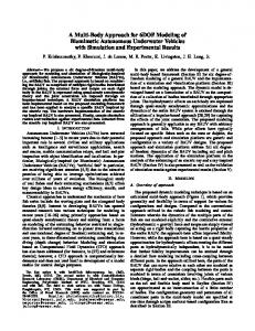
credible data; however, it is also the most costly. Laboratory testing also provides credible information, but it is restricted mainly to subsystem evaluation. Between the extremes of low-cost, low-credibility analytical methods and high-cost, high-credibility testing methods there exists a gap filled by computer simulation (Nassiri et al. 2005a). So computer modeling and simulation can be a middle step between conceptual model and reality, and it is the best way of validation of a model. The architecture of a simulation space and steps has been shown in fig. (1).
is based on mathematical models of the sounding rocket, its payload and the environment, which consist of equations that describe physical laws and logical sequences. The sounding rocket model includes factors such as rocket mass, thrust, aerodynamics, and the equations necessary to calculate the rocket attitude and flight path. The complete 6DoF equations of motion are used in the paper considering the variable mass and inertia, separations, deployment of recovery system, and the most possible anomalies occurring during the flight. The trajectory is computed by integrating numerically the different forces and moments applied to a sounding rocket: gravitation, aerodynamic forces and thrust.
Reality
Model Validation
Model Specification Analysis
Simulation
Computer Model
Programming
Conceptual Model
Model Verification
Figure 1: Architecture of a Simulation Space (Rolfe and Staples 1986) Simulation can play the main role in the design of the vehicle, modification and performance analysis and will result in saving time and reducing costs. For the same reasons and also for the matter of safety, it is important to simulate the trajectory and splashdown area of sounding rockets, which are useful launch vehicles for doing researches and experiments and required to follow a predetermined trajectory for reaching a nominal apogee. There are four basic applications of sounding rocket flight simulations: (1) to establish sounding rocket performance requirements, (2) to design and optimize sounding rocket systems, (3) to assess sounding rocket system performance, and (4) to train users the correct use of the sounding rocket in different situations. The various levels of simulations needed for sounding rocket development and the diversity of simulations used for related analyses. These levels extend from unsophisticated two-dimensional fly-out models to extremely detailed 6DOF models. In this activity the 6DOF method has been adopted in the development of the mathematical model of the simulation apparatus. MATHEMATICAL MODELING OF M&S ENVIRONMENT A sounding rocket flight simulation is a computational tool that calculates the flight path and other important parameters of a sounding rocket by integrating numerically the applied different forces and moments, as it leaves the launcher, goes up to a maximum altitude and comes down slightly by using parachutes to be recovered. A simulation
The model of the environment contains, at a minimum, the atmospheric characteristics and gravity. The physical laws in the simulation are those governing the motion of the rocket and those affecting any simulated subsystems. Inputs to the simulation are parameters likely to change from one computer run to the next, i.e., from one simulated sounding rocket flight experiment to the next. Sounding Rocket Flight Modeling For the purposes of this study, the sounding rocket is assumed as a rigid body with a symmetric mass distribution. The mathematical model of the motion of the sounding rocket is based on Newton’s second law. At each instant of time, the force acting on the sounding rocket results in an instantaneous acceleration of the center of mass of the body. Three basic types of forces act on a sounding rocket and its payload which included in this simulation; the forces of gravity, propulsion, and aerodynamics. The model also simulates the separations and recovery phase (including a drag plate, a drogue chute and a main chute) and which account for all of the forces and inertial characteristics of the sounding rocket and its payload (if applicable) in order to calculate its motion. A sounding rocket flight is consisted of four major phases: Motion in launcher, Powered Flight, Ballistic Flight, and Recovery Flight (Flight under the effect of the parachutes). As the flight conditions, the equations and applied forces and moments are different in each phase hence each of these phases has been modeled and simulated separately (Nassiri et al. 2005b; Nassiri et al. 2004). Equations of Motion Equations of motion can be divided into two major groups: Translational and rotational Equations. The translational equations express inertial acceleration of the instantaneous centre of mass of the flying vehicle as a function of applied forces while the rotational equations calculate angular rates using exerted moments. In a 3DOF model just translational equations of motion are employed but in a 6DOF one, rotational equation of motion is employed in addition. Complete equations of motion utilized in this activity, have been accompanied in (Nassiri et al. 2004).
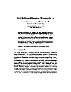
demonstrative apparatus. In addition, due to the mission limitations of the apparatus (i.e. flexibility, interactivity, real-time and operator in loop pipelines), selection of a proper development platform for compliant of arranged missions is inevitable. In this regard, mission chart of this activity has been accompanied in fig. (2) And implementation road map with exploiting MATLAB and Simulink Toolboxes, Blocksets and facilities, has been projected in fig. (3).
IMPLEMENTATION OF THE M&S ENVIRONMENT
In the development, implementation and architecture of M&S environment, initially we should arrange mission chart of the environment and eventually bring into being the implementation road-map of the assorted surveys, methods and tools in a proper platform. As has been declared, the principal intention in the development of the presented approach is to create a swift, productive and
Air Environment Model
Aerodynamics
Simulation States: Position, Orientation, Acceleration & Velocity Vectors
6DOF Nonlinear Dynamics
Propulsion System
External Visual
Instrumentation
Launch Phase M&S
Command
Operator
Operator Gadgets
Recovery Phase
Engineering or Instructor Visualization
Figure 2: The Architecture of the M&S Environment Mission-Chart.
MATLAB Platform
GUI Main M-File
- Data Feeding - Commands
Simulink Invitation
MDL Environment
GUI
Dials & Gauges Operator Visualization Virtual Reality
- Calculations - Presentation of the Results - Saving of the Results
Sounding Rocket 6DOF Dynamics
M-File Invitation
Figure 3: The Implementation Road-Map of the M&S Environment.
MODELING OF THE VIRTUAL WORLD Modeling is used to construct arrangements that fill the role of surrogates for other objects. In all of virtual models from a very simple cube up to sophisticated scale-based engineering models, a common and unique thread is observable: modeling attempts depict an object that expresses definite statements about another, usually more expensive or excellent object(s) in real world. In this paper a sounding rocket is a particular kind sample.
Because of picking up MATLAB platform in the implementation of the M&S environment and in the creation of virtual world, we can use various tools and applications in which are linkable to the main platform. Some of them are such as: 1.
Exploiting Simulink and Virtual Reality (VR) Toolbox of MATLAB.
2.
Utilizing AeroSim Blockset (Unmanned Dynamics 2005) which can interface with Microsoft Flight
Simulator in the Windows operating system or FlightGear open source flight simulator in the various platforms such as Windows, Linux, and UNIX, Apple, and Mac operating systems. Definitely in this method, extreme changes in mathematic modeling and specialization of related blocks for a sounding rocket is inevitable. In addition virtual objects, world modeling and implementation should be complied with related 3D Graphics applications. 3.
Developing our own 3D Graphics application with using OpenGl and/or DirectX® (Direct3D®, DirectInput, and DirectSound … ) programming facilities. Microsoft Visual C++ could be a perfect platform for developing and implementation of the virtual world and visualization of the modelled objects by an Object Oriented scheme (Saghafi and Amiri Atashgah 2002). (This activity is under construction with taking advantages of performed research activity in integrated simulation software of a UAV and Helicopter).
In all of the portrayed ways, some general concepts and principles of visualization, representation and rendering should be perceived. Visualized images in computer screen from a virtual world consists a consequence of gigantic computations such as transformations, rotations and mappings from points, surfaces and volumes in vector- matrix fashion. Initially a geometric model of a virtual world and objects should be generated and implemented with 3D Graphics Engines. In a virtual world from modeling up to rendering we confront with four coordinate systems. World coordinate, local (Object) coordinate, observer (camera) coordinate and screen coordinate systems are most common in this area (DirectX9b SDK 2005). In addition the transformation pipeline from the vertices of modeled objects up to the rasterization (making an image into a bitmap image) process has been depicted in figure (4). In the development and implementation of the VR environment, initially we should arrange a 3D database of the real world and after that, construct the conceptual and geometric models of simulated objects with exploitation of related modeling packages i.e. 3D Studio Max. For producing photorealistic objects, we can generate texture maps of 3D objects in any photo painting software and wrap around it with utilization of appropriate Modeling software. Related to this, is the exported file formats from the modeling software. We should be aware of the appropriate and convenient input file formats for the VR Toolbox that could be used in MATLAB VR Editor. Some of them are VRM and 3DS file formats. In MATLAB VR Editor, each scenery object can be altered. Before any activity, the VR Blockset from MATLAB Virtual Reality Toolbox should be joined to the mathematical model Blocksets. After that VR Dialog Box can be managed regarding to the implementation of moving objects rotational and transformational characteristics. The road map of modeling, development and implementation of VR notions in MATLAB have been portrayed in figure (5).
Vertices
Transformation Pipeline
World Transformation
View Transformation
Projection Transformation
Clipping and Viewport Scaling
Rasterizer
Figure 4: Transformation Pipeline in 3D graphics engines (DirectX9b SDK 2005) Table 1: List of the Program Inputs and Outputs Program Inputs
Program Outputs
Rocket Geometry
Flight trajectory
Mass & Inertia Properties
Linear and Angular Acceleration and Velocity during flight
Launcher Specifications
Exerted Force and Moments
Motor Specifications: Thrust, Burnout Time Mission Strategy: Separation time, Parachute Deployment time.
Parachute Opening Shock Impact Velocity
Atmospheric Data and Wind Profile Aerodynamics Data
DESCRIPTION OF THE M&S ENVIRONMENT Initially we should define an operator in this class of the M&S environment. An operator could be a designer, analyzer engineer and/or ground station supervisor. A designer and/or engineer are able treat with real-time data visualization facilities and gadgets such as 2D and 3D graphs in which states of simulated vehicle has been depicted. In addition, an operator with taking advantage of 3D VR window is able to observe intuitive representation of the simulation results, comprehend and sense 3D vehicle orientation data with arranged instruments in the M&S environment. A complete protraction of the M&S apparatus has been offered in figure (6). The main window of the environment consists of interactive facilities for; (1) Opening details of mathematical modeling blocks, (2) Reopening of the VR window, (3) Re-opening of the indicators window (4) Modifying simulation data, (5) plotting simulation results and (6) Exiting the simulation environment. Through the Simulation Results box, simulation states may be plotted in real-time and/or after running of simulation calculations. Simulation inputs and outputs have been presented in table (1). With exploitation of the Simulation Dialogs box, user can select & manipulate the simulation inputs which include; nonlinear aerodynamics, propulsion system, wind profile and data files of the air environment look-up table, parachute data, weights and mission profile constants.
Conceptual Model
PhotoShop
Geometric Model
3D Studio Max
3DS or VRM file format
Simulink Environment
MATLAB VRML Editor
Real World
Moving Objects Specifications Implementation
Loading VRML file
VRML Viewer Blockset Implementation
Figure 5: The Road-Map of Modeling, Development and Implementation of the VR Notions in MATLAB.
OPTIMIZATIONS AND REAL-TIME NOTIFICATIONS
•
In the development and implementation of the M&S environment, some minute strategies in geometric modeling, programming, architecture of Simulink Blocksets, MATLAB function calls and data manipulating for vouching for real-time aspects, should be considered.
•
Some important notes in the real-time considerations are:
•
1.
2.
In the computations point of view: • Applying summation instead of multiplication in doubling or tripling cases. • Applying multiplication instead of dividing of constant cases. • Organizing reiterated and same calculations just only one time. • Pre-estimation of unaltered expressions before simulation initial time-step. • Using low level platforms. • Abdication of the if statements and switches. • Denying the trigonometric functions and using optimized expanded user defined functions. • Using optimized integration method or step size. In the declarations: • Utilizing the smallest type as much as possible for sample: word in contrast with integer, float against double and etc. • Exploiting global variables against the local ones. • Using pointers with respect to the simple declarations. • Abdication of the objective data to the simple ones.
3.
In MATLAB and Simulink: refer to the (Mathworks inc. 2005).
4.
In the VR implementation (Mathworks inc. 2005), (DirectX 9b SDK 2005): • Using the optimized meshes and scenery with utilizing the OptimizeMesh modifier of 3D Studio Max.
• •
5.
Exploiting colours versus textures or optimized texture size in power of two (32*32, 64*64, 128*128… ). Setting up dotted or meshed rendering against solid one. Decreasing the camera field of view. Rendering the animations with lighting and shading-off condition or decreasing the light sources. Optimizing the scenery details.
Hardware and Operating system Notifications: • Utilizing windows XP (the fastest OS) versus other windows, if we are in Microsoft platforms. • Utilizing higher RAM for the system and/or the graphics card. • Utilizing faster graphics card with supporting 3D rendering capabilities. • Cleaning up and uninstalling the unnecessary files and softwares in Windows Operating System.
CONCLUSIONS This paper has offered an approach for developing a flexible, interactive, and real-time 6DOF modeling and simulation environment. The most important features of the system are: 1.
Development and implementation is based on MATLAB and Simulink Toolboxes, Blocksets and facilities.
2.
In construction of the operator interface the facilities such as: M-File Programming, Graphical User Interfaces (GUI), Graphics and 3-D Visualization, Aerospace Blockset, Dials and Gauges Toolbox and finally Virtual Reality Toolbox (VR) have been combined in a single workspace.
3.
Optimization keynotes in this area are very significant subjects specifically in modification process. Some main aspects are; In the computations point of view, In the declarations, In MATLAB and Simulink utilization, In the VR implementation, Hardware and Operating system Notifications.
Indicated platform is a basic activity for development of an advanced modeling and simulation environment with exploiting Microsoft Visual C++, MATLAB wizards and DirectX and/or OpenGl 3D Graphics engines (Future marching). The advantages of such an environment are; (1) Utilization of specialized hardware in loop interface, (2) Vast Virtual Reality interface with applying optimization keynotes. (3) Portability advantages by utilization of C++ and OpenGl engine. (4) Using MATLAB-Simulink wizards with MS C++ developing environment.
Mathworks Inc. 2005. MATLAB 7 (Release 14). USA. wwwLink: www.mathworks.com Nassiri, N.; S. Haghighat and J. Roushanian. 2004. “Stochastic Flight Simulation Applied to a Sounding Rocket” Proceeding of 55th International Astronautical congress, VancouverCanada, (Oct). Nassiri, N.; J. Roushanian and S. Haghighat. 2005a. “Design of Multipurpose Software for 6DOF Simulation of a Sounding Rocket Trajectory” International Mechanical Engineering Conference, Kuwait, Nassiri, N.; S. Haghighat and J. Roushanian. 2005b. “Trajectory Simulation of a Sounding Rocket Payload during Reentry Phase” Proceeding of 4th International Symposium Atmospheric Reentry Vehicles & Systems, Arc chon - France, (Mar).
Aerospace Research
Rolfe, J.M. and K.J. Staples. 1986. “Flight Simulation” Cambridge University Press. Saghafi, F. and M.A. Amiri Atashgah. 2002. “Developing a Flight Simulation Software for Feasibility Study of Converting a Target Unmanned Aircraft to an Anti Helicopter TV Guided Weapon.” Proceeding of 4th Iranian Aerospace Society Conference (In the Persian Texts), Tehran, Iran, (Dec). Unmanned Dynamics, LLC. 2005. Aeronautical Simulation Blockset for MATLAB. www-Link: www.u_dynamics.com
AUTHOR BIOGRAPHY
Figure 6: Depictions of the Modeling and Simulation Environment
REFERENCES Brooks, F.P. 1999. “What's Real about Virtual Reality?” Special Report, University of North Carolina ay Chapel Hill (Nov. /Dec). DirectX9b SDK. 2005. Microsoft www.microsoft.com/windows/directx.
Co.
www-Link:
Harmon, S.Y. 2002. “Can there be a Science of Simulation? Why should we care? ” The Society for Modeling and Simulation International. Modeling and Simulation Magazine, Volume 1, No.1 (Jan-Mar), 8.
MOHAMMAD ALI AMIRI ATASHGAH was born on Sep. 21, 1977, in Ardebil, Iran, and grew up in Karaj and Tehran. He received a bachelor’s degree in aerospace engineering from the Sharif University of Technology, Tehran, Iran in 1999, and then received a Master of Science degree in aerospace engineering with the majority of flight dynamics and control from the Sharif University of Technology, Tehran, Iran in 2001. Following graduation, he moved to Isfahan, Iran and entered to HESA aircraft industries as a senior aircraft designer and research engineer in modeling and simulation for 3 years. After that he moved to Tehran, Iran in 2004 and entered to Aerospace Research Institute, Ministry of Science, Research and Technology, Tehran, Iran. His scientific activities and interests are: Aircraft design (Twin Turbo Prop and UAV), 6DOF visual simulation and control (real-time and pilot-inloop), multimedia and game programming with utilization of DirectX® and Visual C++.