JOURNAL OF ADVANCEMENT IN ENGINEERING AND TECHNOLOGY Journal homepage: http://scienceq.org/Journals/JAET.php
Open Access
Research Article
Development of a Microcontoller-Based Motor Speed Control System Using Intel 8051 Ganiyu, R. A.1, Shoewu, O.2 , Olatinwo, S. O.3 , Omitola, O. O.4 1, 3. Department of Computer Science and Engineering, Ladoke Akintola University of Technology, Ogbomoso, Oyo State, Nigeria.
2. Department of Electronic and Computer Engineering, Lagos State University, Epe Campus, Nigeria. 4. Department of Computer Engineering, Afe Babalola University, Ado Ekiti, Ekiti State, Nigeria.
*Corresponding author: Ganiyu, R. A., Shoewu, O. Department of Computer Science and Engineering, Ladoke Akintola University of Technology, Ogbomoso, Oyo State, Nigeria. E-mail:
[email protected],
[email protected] Received: February 15, 2014, Accepted: March 10, 2014, Published: March 12, 2014.
ABSTRACT This paper presents the development of a microcontroller based motor speed control system using Intel 8051. The motor speed control system under consideration entails a closed loop real time control system, where a very high resolution optical encoder is coupled to the motor shaft to provide the feedback speed signal via the microcontroller (Intel 8051). The microcontroller acts as a proportional controller with different values of gain (Kp). In order to maintain a constant speed, the pulse width modulation signal generated via the microcontroller is sent to the motor driver so as to vary the voltage supply to motor. A visual studio (C#) program, which provides the graphical user interface for the user to input the desired speed, is developed. Thus, the developed system could be used to monitor the performance of motor under varying loads through the controller. Keyword: Motor, Microcontroller, Control, Speed, Intel 8051 INTRODUCTION Direct Current (DC) motor has already become an important device configuration for many applications across a wide range of power and speeds. The essence of control and excellent performance of the motors will ensure that the number of applications using them will continue grow for the foreseeable future. An electric motor is an electromechanical device that converts electrical energy into mechanical energy. Most electric motors operate through the interaction of magnetic fields and current-carrying conductors to generate force. The reverse process, producing electrical energy from mechanical energy, is done by generators such as an alternator or a dynamo; some electric motors can also be used as generators, for example, a traction motor on a vehicle may perform both tasks. Electric motors and generators are commonly referred to as electric machines. Electric motors are found in applications as diverse as industrial fans, blowers and pumps, machine tools, household appliances, power tools, and disk drives. They may be powered by direct current, e.g., a battery powered portable device or motor vehicle, or by alternating current from a central electrical distribution grid or inverter. The smallest motors may be found in electric wristwatches. Medium-size motors of highly standardized dimensions and characteristics provide convenient mechanical power for industrial uses. The very largest electric motors are used for J. of Advancement in Engineering and Technology: Voume1/Issue2
propulsion of ships, pipeline compressors, and water pumps with ratings in the millions of watts. Electric motors may be classified by the source of electric power, by their internal construction, by their application, or by the type of motion they give [1]. In this paper we are concern majorly on controlling DC Motors. DC motor is an electric motor that runs on direct current (DC) electricity. DC motors were used to run machinery, often eliminating the need for a local steam engine or internal combustion engine. DC motors can operate directly from rechargeable batteries, providing the motive power for the first electric vehicles. Today DC motors are still found in applications as small as toys and disk drives, or in large sizes to operate steel rolling mills and paper machines. Modern DC motors are nearly always operated in conjunction with power electronic devices [1]. Two important performance parameters of DC motors are the motor constants, Kv and Km. The brushed DC electric motor generates torque directly from DC power supplied to the motor by using internal commutation, stationary magnets (permanent or electromagnets), and rotating electrical magnets. Like all electric motors or generators, torque is produced by the principle of Lorentz force, which states that any current-carrying conductor placed within an external magnetic field experiences a torque or force known as Lorentz force [2]. ISSN: 2348-2931
1
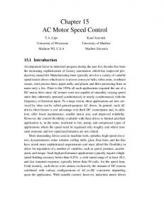
DC motor Speed Controller For precise speed control of motor system, closed-loop control is normally used. Basically, the flow chart of the speed control is shown in Figure 1. The speed, which is sensed by analog sensing devices (e.g., tachometer), is compared with the reference speed to generate the error signal and to vary the armature voltage of the motor.
a constant voltage proportional to the phase difference and the steady-state motor speed would be maintained at a fixed value irrespective of the load on the motor. Any disturbances contributing to the speed change would result in a phase difference and the output of the phase detector would respond immediately to vary the speed of the motor in such direction and magnitude as to retain the locking of the reference and feedback frequencies fi. Speed Control by Using PWM and Full H Bridge Motor Drive
Figure 3: Simple motor circuit
Figure 1: Basic Flow chart of DC motor speed control [7] There are several controllers that can used to control the speed of the motor such as by using thyristor, phase-locked-loop control, chopper circuit, Fuzzy Logic Controller but this paper discuss only phase-locked loop and PWM technique. Phase-Locked-Loop (PLL) Control The block diagram of a converter-fed dc motor drive with phase-locked-loop control is shown in Figure 2. In a phase-locked-loop (PLL) control system, the motor speed is converted to a digital pulse train by using a speed encoder. The output of the encoder acts as the speed feedback signal of frequency fr. The phase detector compares the reference pulse train (or frequency) fr with the feedback frequency fo and provides a pulse-width-modulated (PWM) output voltage Ve that is e proportional to the difference in phases and frequencies of the reference and feedback pulse trains. The phase detector (or comparator) is available in integrated circuits. A low-pass loop filter converts the pulse train Ve to continuous dc level Vc , which e c varies the output of the power converter and in turn the motor speed.
Let us consider a simple circuit that connects a battery as power supply through a switch MOSFET (Metal-Oxide-Semiconductor Field Effect Transistor) as shown in Figure 3 [6]. When the switch is closed, the motor sees 12 Volts, and when it is open it sees 0 Volts. If the switch is open for the same amount of time as it is closed, the motor will see an average of 6 Volts, and will run more slowly accordingly. This on-off switching is performed by power MOSFETs. A MOSFET (Metal-Oxide-Semiconductor Field Effect Transistor) is a device that can turn very large currents on and off under the control of a low signal level voltage. The average of voltage that supply to DC motor is given by,
where Vave = average voltage supply to DC motor ton = time ON of switches T = period of PWM T on /T = DC, duty cycle
Figure 4.: PWM signal Figure 2, Phase-locked loop control system When the motor runs at the same speed as the reference pulse train, the two frequencies would be synchronized (or locked) together with a phase difference. The output of the phase detector would be J. of Advancement in Engineering and Technology: Voume1/Issue2
As the amount of time that the voltage is on increases compared with the amount of time that it is off, the average speed of the motor increases and vice versa.
ISSN: 2348-2931
2
The Microcontroller Microcontrollers must contain at least two primary components – random access memory (RAM), and an instruction set. RAM is a type of internal logic unit that stores information temporarily. RAM contents disappear when the power is turned off. While RAM is used to hold any kind of data, some RAM is specialized, referred to as registers. The instruction set is a list of all commands and their corresponding functions. During operation, the microcontroller will step through a program (the firmware). Each valid instruction set and the matching internal hardware that differentiate one microcontroller from another [8]. Most microcontrollers also contain read-only memory (ROM), programmable read-only memory (PROM), or erasable programmable read-only memory (EPROM). Al1 of these memories are permanent: they retain what is programmed into them even during loss of power. They are used to store the firmware that tells the microcontroller how to operate. They are also used to store permanent lookup tables. Often these memories do not reside in the microcontroller; instead, they are contained in external ICs, and the instructions are fetched as the microcontroller runs. This enables quick and low-cost updates to the firmware by replacing the ROM. Where would a microcontroller be without some way of communicating with the outside world? This job is left to input/output (I/O) port pins. The number of I/O pins per controllers varies greatly, plus each I/O pin can be programmed as an input or output (or even switch during the running of a program). The load (current draw) that each pin can drive is usually low. If the output is expected to be a heavy load, then it is essential to use a driver chip or transistor buffer. Most microcontrollers contain circuitry to generate the system clock. This square wave is the heartbeat of the microcontroller and all operations are synchronized to it. Obviously, it controls the speed at which the microcontroller functions. All that needed to complete the clock circuit would be the crystal or RC components. We can, therefore precisely select the operating speed critical to many applications. To summarize, a microcontroller contains (in one chip) two or more of the following elements in order of importance [9]: i. Instruction set ii. RAM iii. ROM,PROM or EPROM iv. I/O ports v. Clock generator vi. Reset function vii. Watchdog timer viii. Serial port ix. Interrupts x. Timers xi. Analog-to-digital converters xii. Digital-to-analog converters A typical Intel 8051 microcontroller schematic pin configuration is shown in Figure 5 while its simulator is depicted in Figure 6.
J. of Advancement in Engineering and Technology: Voume1/Issue2
Figure 5: Pin Diagram of MC 8051
Figure 6: Microcontroller 8051 Simulator RS232 Serial Port RS232 is a popular communications protocol for connecting modems and data acquisition devices to computers. RS232 devices can be plugged straight into the computer's serial port (also known as the COM or Comms port). Examples of data acquisition devices include GPS receivers, electronic balances, data loggers, temperature interfaces and other measurement instruments. A nine pin D plug has become the standard fitting for the serial ports of PCs. The pin connections used are as shown in Table 1. The connector on the PC has male pins; therefore the mating cable needs to terminate in a DB9/F (Female pin) connector. Table 1: RS232 pin assignments (DB9 PC signal set) [8] Pin 1
Input
Pin 2
Input
Pin 3
Output
Pin 4
Output
Pin 5 Pin 6
Input
Data Carrier Detect Received RXD Data Transmitte TXD d Data Data DTR Terminal Ready Signal Ground DSR Data Set
DCD
ISSN: 2348-2931
3
Pin 7
Output
RTS
Pin 8
Input
CTS
Pin 9
Input
RI
Ready Request To Send Clear To Send Ring Indicator
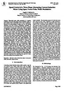
METHODOLOGY DC Motor Speed Control Architecture The actual speed of DC motor will be measured by encoder and feedback to microcontroller. In microcontroller, it will calculate the error between the desired speed with the actual speed. The error will determine duty cycle of pulse-width- modulation (PWM) in microcontroller. Then, the duty cycle will send to DC motor driver either accelerate or decelerate DC motor to maintain it at desired speed. Intel 8051 Microcontroller
Feedback speed
DC Motor
Motor Drive
Actual Speed
Encoder
Host PC
Speed Display
Figure 7: The block diagram of the DC Motor Architecture Hardware Implementation The hardware implementation is carried out with many components like Optical encoder, 5V power supply, microcontroller 8051, pulse-width-modulation (PWM), RS232 serial communication of microcontroller to the PC for real speed monitoring, DC Motor drive, loading unit LU150L and software implementation. Some of this component is discuss below. DC Motor Drive If a DC motor is connected directly to the voltage supply, the constant power will be supplied to the DC motor all the time. Due to the constant power to motor, the speed of motor will slow down when the load is heavier and speed up when the load is lighter. So, DC motor drive is needed where we can control the magnitude of supply voltage in order to control the speed of DC motor. DC motor drive is used in this paper as a dual full bridge driver, chip L298. The operating supply voltage of chip L298 is up to 46V and the total DC current up to 4A. The schematic diagram is depicted in Figure8.
Loading Unit LU150L For DC motor speed control with application of varies loads, a loading unit LU150L is used. It has two U shape magnets with a small space between it. Without LU150L, the disc that fixed at the motor shaft can run smoothly at the constant speed. With the presence of LU150L when the motor is running, the disc will cut the magnetic flux field and it becomes a load to the motor. Thus, motor will slow down. The position of the magnets have been defined as no load, normal load and overload condition as shown in Figure 8. In this work, a controller has been designed to maintain speed back to the desired speed by using microcontroller. The Visual Studio Programming Software Microsoft Visual Studio is an integrated development environment (IDE) from Microsoft. It is used to develop console and graphical user interface applications along with Windows Forms applications, web sites, web applications, and web services in both native code together with managed code for all platforms supported by Microsoft Windows, Windows Mobile, Windows CE, .NET Framework, .NET Compact Framework and Microsoft Silverlight. Visual Studio includes a code editor supporting IntelliSense as well as code refactoring. The integrated debugger works both as a source-level debugger and a machine-level debugger. Other built-in tools include a forms designer for building GUI applications, web designer, class designer, and database schema designer. It accepts plug-ins that enhance the functionality at almost every level—including adding support for source-control systems (like Subversion and Visual SourceSafe) and adding new toolsets like editors and visual designers for domain-specific languages or toolsets for other aspects of the software development lifecycle (like the Team Foundation Server client: Team Explorer). Visual Studio supports different programming languages by means of language services, which allow the code editor and debugger to support (to varying degrees) nearly any programming language, provided a language-specific service exists. Built-in languages include C/C++ (via Visual C++), VB.NET (via Visual Basic .NET), C# (via Visual C#), and F# (as of Visual Studio 2010). In this work only the C# language of the visual studio was used. Implementation Procedures In this work, an experiment was conducted to determine the relationship between voltage supply and speed. The implementation procedures are as follows: i. The circuit was connected as shown in Figure 9. ii. Voltage of 0.5V was supplied to motor. iii. Value of rpm at tachometer was recorded iv. The voltage increased in steps of 0.5V until 16V and step 3 was repeated.
Figure 8: Bi-direction of Speed Motor Control J. of Advancement in Engineering and Technology: Voume1/Issue2
Figure 9: Tachometer Encoder Experiment ISSN: 2348-2931
4
v. The circuit as shown in Figure 10 was designed by changing tachometer with the optical encoder that has been built. The output waveform from optical encoder was connected to oscilloscope.
Figure 10: Optical encoder Experiment vi. Step 2 was repeated. vii. The readings for the frequency of oscilloscope were recorded.
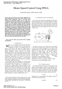
viii. Step 4 was repeated. ix. A graph of rpm-voltage was plotted for both tachometer and optical encoder. x. Based on graphs, both result was compared and the accuracy of optical encoder that has been built is found. RESULTS AND DISCUSSION Experimental Result From the experiment, the data recorded was as depicted in Table 2. A graph of speed versus voltage supply by using tachometer and optical encoder is shown in Figure 11.
Voltage Supply (V)
0.0 0.5 1.0 1.5 2.0 2.5 3.0 3.5 4.0 4.5 5.0 5.5 6.0 6.5 7.0 7.5 8.0 8.5 9.0 9.5 10.0 10.5 11.0 11.5 12.0 12.5 13.0 13.5
Speed (rpm ) Tachometer1
0 0 100 240 330 410 550 640 770 860 970 1090 1200 1280 1400 1490 1590 1700 1820 1920 2030 2140 2230 2340 2480 2570 2690 2810
Speed (rpm ) 2 Optical Encoder
%100rpmrpmrp mError%121×−=
0.00 0.00 99.60 230.06 315.79 420.21 553.51 655.02 767.26 854.70 940.44 1048.95 1164.60 1258.39 1358.70 1467.71 1552.80 1648.35 1794.26 1870.32 1968.50 2074.69 2228.83 2272.73 2400.00 2516.78 2617.80 2702.70
0.00 0.00 0.40 4.14 4.31 2.49 0.64 2.35 0.36 0.62 3.05 3.77 2.95 1.69 2.95 1.50 2.34 3.04 1.41 2.59 3.03 3.05 0.05 2.87 3.23 2.07 2.68 3.82
DC Motor Speed Control Result For P controller, as the controller proportional gain, Kp is increased, the response to set point changes becomes more oscillatory, commonly called under damped (Figure 12a). In this project, the speed response will give an under damped response when Kp=1. At some greater gain, the response of the control loop becomes a steady-state oscillation (Figure 12b). The system is called “marginally stable” (Figure 12c). If the gain is increased past the point where steady oscillation is observed, the control loop will become unstable and the oscillations will increase in amplitude. Figure11: Graph of speed versus Voltage supply The accuracy of the optical encoder can be checked by calculate its standard deviation, s for percentage of error by using
The standard deviation percentage of error is quite small, so it can be concluded that the reading of the optical encoder for speed measurement is quite reliable which is given by: rpm = 207.16V -80.89 , where rpm = motor speed and V = voltage supply to motor
Figure 12: Types of oscillatory response: (a) under-damped (b) sustained Oscillation (c) unstable.
Table 2: Relationship of voltage supply and motor speed J. of Advancement in Engineering and Technology: Voume1/Issue2
ISSN: 2348-2931
5
From graph speed versus time for speed from 190.74 rpm to 762.95 rpm, the controller is able to control the speed at their desired speed when applying normal load and overload. Without controller, the motor will slow down or maybe die out. Also, Figure 4.3 shows a free body diagram of the disc based on the relationship Tmotor – Tload = Jω, where J, Tload, Tmotor and ω are moment of inertia of the wheel about the axis of rotation, torque induced by load, torque induced by voltage supply and speed motor respectively. If the load is removed suddenly (i.e. Tload = 0), the motor would speed up before Tmotor motor is changed. With the microcontroller, the motor is able to return back to the desired speed in a period of time. For motor speed in the range of 953.69 rpm to 1716.64 rpm, the controller can control at normal load but not in overload condition. In overload condition, the speed response is oscillating until the load is removed. It is because Tmotor induced by the voltage supply (maximum 12V) is not enough to overcome the Tload of overload condition within this speed.
w
J T motor T load
Figure 13: Free body diagram of the disc CONCLUSION Recent developments in science and technology provide a wide range scope of applications of high performance DC motor drives in area such as rolling mills, chemical process, electric trains, robotic manipulators and the home electric appliances require speed controllers to perform tasks. DC motors have speed control capabilities, which means that speed, torque and even direction of rotation can be changed at any time to meet new condition. The controller will maintain the speed at desired speed when there is a variation of load. By varying the PWM signal from microcontroller (P controller) to the motor driver, motor speed can be controlled back to desired value easily. For this paper, by applying Kp =1 to P controller in microcontroller, the speed response become under damped response. If Kp < 1, the speed response is not satisfied. At some greater gain, the speed response of the control loop becomes a steady-state oscillation. If the gain is
increased past the point where steady oscillation is observed, the control loop will become unstable and the oscillations will increase in amplitude. The motor will suddenly speed up and be damaged. Future research will be geared towards formulating a mathematical model from the graph of motor speed response obtained. The mathematical model will be simulated using software such as MATLAB to improve motor speed response via controller packages such as PID controller and Fuzzy Logic Controller. REFERENCES 1. http://www.wikipedia.com/Motor.html 2. M. H. Rashid, Power Electronics Circuits, Devices and Applications, third ed., Prentice Hall, United States of America, 2004. 3. C. A. Adkins and M. A. Marra, Modeling of a Phase-Locked Loop Servo Controller with Encoder Feedback, IEEE Spectrum, (1999) 51-56. 4. A.W Moore, Phase-Locked Loops for Motor-Speed Control, IEEE Spectrum, (1973) 61-67. 5. P. C. Sen and M. L. MacDonald, Thyristorized DC Drives with Regenerative Braking and Speed Reversal, IEEE Transactions on Energy Conversion, Vol. IECI-25 (1978) 347-354. 6. http://homepages.which.net/paul.hills/SpeedControl/Speed ControllersBody.html 7. A. Z. Ahmad and M. N. Taib, A study On the DC Motor Speed Control by Using Back-EMF Voltage, Asia SENSE SENSOR, (2003), 359-364. 8. I. John, PIC Microcontroller Project Book, second ed., Mc Graw-Hill, Singapore, 2000. 9. L. A. Duarte. The Microcontroller Beginner’s Handbook, second ed., Prompt Publication, United States of America, 1998. 10. http://www.airborn.com.au/rs232.html 11. MPLAB IDE, Simulator, Editor User’s Guide 12. J. C. Bradley, A. C. Millspaugh, Programming in Visual Basic 6.0. Version 6, McGraw-Hill/Irwin, New York, 2002. 13. http://www.seattlerobotics.org/encoder 14. F. G. Sjhinskey, Process Control Systems, second ed., McGraw-Hill Book Company, Singapore, 2003. 15. P. N. Paraskevopoulos, Modern Control Engineering, Marcel Dekker, Inc., New York, 2002. 16. N. S. Nise, Control Systems Engineering, second ed., The Benjamin/Cummings Publishing Company Inc., California, 1995
Citation: Ganiyu, R. A., Shoewu, O., et al (2014) Development of a Microcontoller-Based Motor Speed Control System Using Intel 8051.J. of Advancement in Engineering and Technology. V1I2. Copyright: © 2014 Ganiyu, R. A., Shoewu, O.. This is an open-access article distributed under the terms of the Creative Commons Attribution License, which permits unrestricted use, distribution, and reproduction in any medium, provided the original author and source are credited.
J. of Advancement in Engineering and Technology: Voume1/Issue2
ISSN: 2348-2931
6