Rajshahi University Journal of Science & Engineering Vol. 43: 73-80, 2015
ISSN 2309-0952
Development of a Technical Device Named GPS Based Walking Stick for the Blind Umme Kawsar Alam*, Fazle Rabby and M. T. Islam Dept. of Mechanical Engineering and Computer Science & Engineering, Chittagong University of Engineering & Technology, Chittagong 4349, Bangladesh. *Corresponding Author:
[email protected] Abstract Generally, blind people use a traditional cane (known as white cane) for moving from one place to another. Although, white cane is the international symbol of blindness, it could not help them to detect place and to avoid obstacles. In this paper, we represent a model of walking stick for blind people. It consists of GPS module, GPS Antenna, Arduino, ultrasonic sensor and buzzer. This stick can detect place and obstacles. Position detection part is done with GPS module and GPS antenna. Ultrasonic sensor is used for detecting obstacles. Here, the buzzer produces two types of sound. When the blind reaches to his destination, buzzer buzzes continuously. When the blind faces any obstacles, buzzer buzzes with interruption. By discovering these two types of sound, blind can be confirmed about his destination and also can avoid obstacles in front of him. The whole system is designed to be small, light and is used in conjunction with the white cane so that it could ensure safety of the blind.
Keywords: arduino; buzzer; GPS antenna; GPS module; walking stick. INTRODUCTION A. General The eyes are the most important sense of organ of human. We perceive up to 80 percent of all impressions by means of our sight. According to the august, 2014 statistics of World Health Organization, 285 million people are judged to be visually impaired worldwide, 39 million are blind and 246 have low vision. The people with low vision or no vision suffers from various problems. Mobility and orientation are two of them [1]. The traditional and oldest mobility aids for the blind are the white cane and guide dog. As white cane is the international symbol of blindness, the visual presence of white cane helps to understand others that the user is blind. It also helps the blind to reach a destination and avoid obstacles in the ground but it could not protect him from all levels of obstacles. On the other hand, Guide dog knows the path and is able to observe and break down complex situations like cross walks, stairs, potential danger and more. But guide dogs are still far from being affordable and their average working time is limited, an average of 7 years. So these traditional mobility aids have many drawbacks. For improving this traditional walking aid, here, GPS based walking stick with obstacle detecting sensor for the blind is proposed and developed [2,3]. B. Previous Work A number of navigation systems for aiding the blind have been developed already. These developed systems can be categorized into two groups [1]. The beginning group is Electronic Travel Aids (ETAs) and the second group is Electronic Orientation Aids
74
Rajshahi Univ. j. sci. & eng.
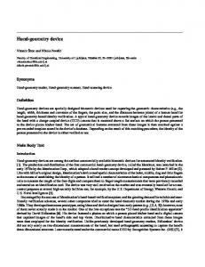
(EOAs). ETAs are designed to create a safe journey by detecting obstacles using ultrasonic and proximity sensor. EOAs are designed to detect desired destination using GPS and location based service. A GPS based blind stick with ultrasonic and proximity sensor for detecting obstacle was developed [2]. It used stereo camera and dual feedback system. A mobility aid for the blind and partially sighted people which is linked with a GSM-GPS module to pinpoint the location of the user was also created [3]. This aid also used ultrasound sensor for detecting obstacles. A GPS navigator with audio guidance for the blind walking on campus was developed [4]. Another system for detecting obstacles was created [5]. It was a wheeled stick. When it detected obstacles, it automatically steered around and made the user to follow the obstacles free path without any conscious effort. SYSTEM ARCHITECTURE In the following section we will describe the system architecture, hardware components and software architecture. C. System Architecture As indicated in Fig. 1, the architecture of the system consists of 5 essential components: Arduino, GPS module with GPS antenna, ultrasonic sensor, buzzer and battery. GPS Module Arduino Buzzer
Ultrasonic Sensor Battery
Fig. 1.
Block diagram of the system.
The longitude and latitude of the final destination of the blind are programmed with the Arduino. Arduino is connected with regulated power supply. When the blind people walk with the stick, connected GPS module continuously shows their current longitude and latitude. So, the Arduino has the programmed value and connected GPS module shows the current value of the user’s location. When these two values become equal to each other, buzzer buzzes continuously. It indicates that, blind has been able to reach to his destination successfully. By hearing this type of continuous sound from the buzzer, the blind person will be confirmed that he has reached the place where he wanted to go. At the tip of the stick, there is an ultrasonic sensor. If any sort of obstacles is available before the user, sensor automatically detects it and makes the buzzer to beep with interruption. Thus, the blind can avoid any kind of obstacles in his way [6].
Development of a Technical Device Named GPS Based Walking Stick for the Blind
75
D. Hardware Components The total system is developed to offer blind people with a larger level of independence in their everyday life. It includes Venus GPS with SMA Connector, GPS antenna, Arduino UNO, Electromechanical buzzer, Ultrasonic sensor HC-SR04 and a 12 Volt Duracell battery. All of these components are linked as shown in Fig. 2. Each component performs a specific job and can be explained as follows: Venus GPS with SMA Connector is the GPS module which computes the user’s position by precisely timing the signals transmitted by GPS satellites high above the Earth [7]. Each satellite continually transmits messages that include: • The time the message was transmitted and, • Satellite position at the time of message transmission.
(a)
Fig. 2.
(b)
Hardware components of the system: (a) circuit diagram, (b) fabricated stick
The module computes the difference of the time when each satellite message is received and the time when the message is sent by the satellite. Then, each time difference is multiplied with the velocity of light. Thus, its distance from each satellite is obtained. These distances and satellites' locations are used to compute the location of the module using the trigonometric navigation equations. If the module can receive GPS signals at least from three satellites, it can calculate its 3d position (longitude, latitude, height) [8, 9]. The GPS antenna helps boost the reception signal to a GPS module. It helps the GPS module to “see” the sky without having to be moved. GPS signal which comes from the satellite is very weak. Antenna amplifies this signal and transmits it to the module. It is connected with the GPS module. Arduino UNO is a microcontroller board based on the ATmega328 (datasheet). It has 14 digital input/output pins (of which 6 can be used as PWM outputs), 6 analog inputs, a 16 MHz ceramic resonator, a USB connection, a power jack, an ICSP header, and a reset button. The GPS module, ultrasonic sensor and buzzer all connect with it [10]. Electromechanical buzzer is used for creating two different types of buzzing sound. It is an audio signaling device which is identical to an electric bell without the metal gong. It functions by means of an electromagnet. When an electric current is applied, it produces a
76
Rajshahi Univ. j. sci. & eng.
repetitive buzzing or clanging sound. A relay may be connected to interrupt its own actuating current, causing the contacts to buzz. Often these units were anchored to a wall or ceiling to use it as a sounding board [11]. For detecting obstacles, the ultrasonic sensor HC-SR04 is employed. It consumes 5 volt power and provides 2cm-400cm non contact measurement function. Inside the sensor, this electrical energy is converted into ultrasonic signal. This sound pulse is transmitted by the transmitter of the sensor. If there is any kind of obstacles in front of the sensor, the signal is reflected back from the surface of the object. The reflected echo is received by the sensor’s receiver. Thus the distance of the obstacles from the sensor is measured by considering the time taken by the echo to return back. Its accuracy is 3mm. Finally, the power supply is done by using a 12 volt Duracell battery which is connected to the Arduino. E. Software Architecture The software for the system has been developed in the C language. Flowchart for displaying current longitude and latitude of any position on computer screen using GPS module is shown in Fig. 3. The current value is compared with predefined values and if these values are same, immediately Arduino gives instruction to the buzzer to buzz continuously. Figure 4 shows flowchart of this process. If the user faces any obstacles, it obstructs and reflects the ultrasound generated from the transmitter. Receiver of the sensor receives the echo of the ultrasound and calculates the distance of the obstacles. When the distance of the obstacles becomes less than or equal to the programmed value (here, 120cm), Arduino gives instruction to the buzzer to buzz with interruption. If the blind hears discontinuous beep from the buzzer, he has to understand that he is going to face an obstacle. Thus a blind person can be confirmed about the existence of an obstacle while he is face to face 120cm away from it and can avoid obstacles in his way. Flowchart of programming the sensor for detecting obstacles is shown in Fig. 5. Start Read data from GPS PIC Extract NMEA string Parse Lat/Long (latitude/longitude) information Send Lat/Long to PC
End Fig. 3.
Flowchart for displaying current longitude and latitude of any position
Development of a Technical Device Named GPS Based Walking Stick for the Blind
Start Read the value of current location. Read the value of predefined location. Check the current value with the predefined value up to 2nd position after the decimal point.
Yes
Does current value match with the predefined value up to 2nd position after the decimal point?
No
Buzzer, HIGH End Fig. 4.
Flowchart of comparing current location with predefined location
Start Generate 40 KHz pulse to Ultrasonic Transmitter (TX) Get the reflection time from the receiver (RX) Calculate the distance of obstacle from the echo time
No
Is the distance of obstacle less than or equal to 120 cm?
Yes Buzzer, HIGH
Delay, 50 sec Buzzer, LOW End Fig. 5.
Flowchart of programming the sensor for detecting obstacles
77
78
Rajshahi Univ. j. sci. & eng.
EXPERIMENTAL RESULT F. Experimental Data Final destination of the blind is programmed on the Arduino. Our first testing is whether the buzzer buzzes at the pinpoint of the programmed location. The result that we got is given in the Table 1. TABLE I.
RESULT OF TESTING IF BUZZER BUZZES AT THE PREDEFINED LOCATION
Serial number
Location of destination (longitude and latitude)
1.
Long: 09150.3533E Lat: 2222.6035N Long: 09158.3382E Lat: 2227.8670N Long: 09150.3684E Lat: 2222.6039N Long: 09150.3127E Lat: 2222.6542N Long: 09158.3564E Lat: 2227.8542N Long:09158.3342E Lat: 2227.8619N Long: 09150.3547E Lat: 2222.6067N Long: 09158.2131E Lat: 2227.1092N Long: 09158.2455E Lat: 2227.1064N Long: 09150.3645E Lat: 2222.6134N
2. 3. 4. 5. 6. 7. 8. 9. 10.
The point at which buzzer starts to buzz Long:09150.3576E Lat: 2222.6023N Long: 09158.3398E Lat: 2227.8676N Long:09150.3695E Lat: 2222.6074N Long: 09150.3113E Lat: 2222.6521N Long: 09158.3586E Lat: 2227.8538N Long:09158.3322E Lat: 2227.8613N Long: 09150.3523E Lat: 2222.6048N Long: 09158.2144E Lat: 2227.1090N Long: 09158.2430E Lat: 2227.1023N Long: 09150.3678E Lat: 2222.6185N
Distance of the point at which buzzer buzzes from the final destination -280 cm +200 cm +160 cm -120 cm +320 cm -200 cm -360 cm +280 cm -120 cm +240 cm
Our second testing was whether the buzzer buzzes discontinuously by detecting any obstacles. Here, buzzer buzzes discontinuously when obstacles remain at a distance of 120 cm. G. Discussion From the performance of the developed blind stick, the following important points are found: • The value of latitude and longitude after 2 spaces from the decimal point changes frequently. GPS module gives different values for the same location at different times for the 3rd and 4th position of the decimal point. As we programmed to match the location up to 2nd position of the decimal point, buzzer starts to buzz before reaching the destination point. But, sometimes, it does not buzz at that point rather it starts buzzing after crossing the predefined location. But it makes no problem because the error is only a few centimeters. The area of the location point can be easily detected with it.
Development of a Technical Device Named GPS Based Walking Stick for the Blind
79
•
This system can only be used for front obstacles detection.
•
Object with low density such as cloth, foam etc. can not reflect back the ultrasound because they have a tendency to absorb sound energy. Thus, these obstacles are difficult to detect at long range.
•
Obstacles with rough surface scatter the incident sound wave and so the receiver of the sensor does not get enough sound energy to detect the presence of it. So, this sensor can detect obstacles easily that have smoother surfaces.
•
Detection of obstacles highly depends upon the surface angle of the obstacles with respect to the acoustic axis of the sensor [12]. If the axis of the obstacle remains perpendicular relative to the axis of the sensor, most of the sound energy will be reflected back and sensor can easily identify the presence of the obstacles. On the other hand, if the surface of the obstacles tilts relative to the axis of the sensor, most of the sound energy will be scattered in other direction and so, sensor could not detect the presence of any obstacles. For properly detection of an obstacle with smooth surface, the angle of tilt should not be greater than 25° [12].
•
For reliable sensing, HC-SR04 requires minimum 0.5m2 surface area of the obstacle.
Dynamic obstacles generally produce sound when they move; blind people develop their sense to detect them. That’s why, in spite of not having dynamic obstacles detection system, this stick can be helpful for the blind. H. Future Work Some improvements that could be made are as follows: • For detecting obstacles all around the user, a stepper motor can be connected. The motor can rotate the ultrasonic sensor 2 times with steep angle 90° and so the sensor can detect not only the front obstacles but also the right and left side obstacles [13]. •
•
For detecting front hole in walking way of the blind, IR proximity sensor can be used as a pit sensor [14].
•
For detecting water pit, a water sensor alarm can be attached at the tip of the stick. As soon as it touches water, it will short the circuit and cause closed circuit. By this, desired output can be got [14].
•
For detecting and avoiding dynamic obstacles, 3D depth sensor can be used [15].
CONCLUSION This paper discusses a walking cane for the blind and visually impaired people. This stick can help its users to be confirmed about their destinations and also to avoid any front barriers in their walking ways. Working procedure and limitations of the systems were discussed as well. References [1]
J.Jafnie Evangeline, “Guide Systems for the Blind Pedestrian Positioning and Artificial Vision”, International Journal of Innovative Science, Engineering & Technology, vol.1, issue 3, pp. 42-44, May 2014.
80
Rajshahi Univ. j. sci. & eng.
[2]
Shruti Dambhare, Prof. A. Sakhare, “Smart stick for Blind: Obstacle Detection, Artificial vision and Real-time assistance via GPS”, International Journal of Computer Applications (IJCA), pp. 31-33, 2011. Abdel Ilah Nour Alshbatat, “Automated Mobility and Orientation System for Blind or Partially Sighted People”, International Journal on smart sensing and intelligent system, pp. 568-582, vol.6, no.2, 2013. Rangsipan Marukatat, Pongmanat Manaspaibool, Benjawan Khaiprapay, and Pornpimon Plienjai, “GPS Navigator for Blind Walking in a Campus”, World Academy of Science, Engineering and Technology, 46, pp. 89-92, 2010. Shraga Shoval, Iwan Ulrich, Johann Borenstein, “Robotics-Based Obstacle-Avoidance Systems for the Blind and Visually Impaired”, Robotics in Bio-Engineering, vol.10, no.1, pp. 9-20, March 2003. Ta-Chung Wang, Tz-Jian Lin, “Unnamed Vehicle Obstacle Detection and Avoidance using Danger Zone Approach”, Transaction of the Canadian Society for Mechanical Engineering, vol.37, no.3, pp. 529-538, 2013. P.V. Ratnam, V. Dhanaraj, K. Papa Rao, “Arm Based Advanced Vehicle Monitoring System with Accidental Alert”, International Journal of Advanced and Innovative Research, vol.1, issue 2, July 2012. Shah Mihir Rajesh, Sanman Bhargava, Soumya B, Mr. K. Sivanathan, “Mission planning and waypoint navigation of a micro quad copter by selectable GPS co-ordinates”, International Journal of Advanced Research in Computer Science and Software Engineering, vol. 4,issue 4, pp. 143-152, April 2014. D. Arunvijay, E. Yuvaraj, “Design of Border Alert System for Fishermen using GPS”, International Journal of Student Research in Technology and Management, vol. 2 (02), pp. 6770, March-April 2014. http://en.wikipedia.org/wiki/Arduino_UNO. http://en.wikipedia.org/wiki/Buzzer. Johann Borenstein, Yoram Koren, “Obstacles avoidance with ultrasonic sensors”, IEEE Journal of Robotics and Automation, vol. 4, no. 2, pp. 213-218, April 1988. Prashant Bhardwaj, Jaspal Singh, “Design and Development of Secure Navigation System for Visually Impaired People”, International Journal of Computer Science & Information Technology, vol.5 (04), pp. 159-164, August 2013. G. Gayathri, M. Vishnupriya, R. Nandhini, Ms. M. Banupriya, “Smart Walking Stick For Visually Impaired”, International Journal of Engineering & Computer Science, vol.3, issue 3, pp. 4057-4061, March 2014. Brian peasley, Stan Brichfield, “Real Time Obstacles Avoidance & Avoidance in the presence of Specular Surface Using an Active 3D Sensor”, unpublished.
[3]
[4]
[5]
[6]
[7]
[8]
[9]
[10] [11] [12] [13]
[14]
[15]