Dec 11, 2017 - where Pi = (Xi, Ωi,Ei) represents the properties of the particle outgoing its i-th collision with the medium. Using these notations, we introduce the ...
Development of an adaptive variance reduction technique for Monte Carlo particle transport Henri Louvin
To cite this version: Henri Louvin. Development of an adaptive variance reduction technique for Monte Carlo particle transport. Computational Physics [physics.comp-ph]. Université Paris-Saclay, 2017. English. .
HAL Id: tel-01661421 https://tel.archives-ouvertes.fr/tel-01661421 Submitted on 11 Dec 2017
HAL is a multi-disciplinary open access archive for the deposit and dissemination of scientific research documents, whether they are published or not. The documents may come from teaching and research institutions in France or abroad, or from public or private research centers.
L’archive ouverte pluridisciplinaire HAL, est destinée au dépôt et à la diffusion de documents scientifiques de niveau recherche, publiés ou non, émanant des établissements d’enseignement et de recherche français ou étrangers, des laboratoires publics ou privés.
NNT : 2017SACLS351
`se de doctorat The ´ Paris-Saclay de l’Universite ´pare ´e a ` l’Universite ´ Paris-Sud pre ´ Ecole doctorale n◦576 ´ Particules, Hadrons, Energie, Noyau, Instrumentation, Image, Cosmos et Simulation (PHENIICS) Sp´ecialit´e de doctorat : Physique des particules par
M. Henri Louvin Development of an adaptive variance reduction technique for Monte Carlo particle transport
Th`ese pr´esent´ee et soutenue a` Saclay, le 12 octobre 2017. Composition du Jury : ´sesquelles M.Pierre De M.Kenneth Burn M.Arnaud Guyader M.Josselin Garnier Mme Odile Petit M.Eric Dumonteil `vre M.Tony Lelie ´ Diop M.Cheikh M’Backe
Professeur (CSNSM, Paris Sud) Professeur (ENEA, Rome) Professeur (UPMC, Paris VI) ´ Professeur (Ecole Polytechnique) Ing´enieure-Chercheure (CEA) Ing´enieur-Chercheur, HDR (IRSN) Professeur (CERMICS, ENPC) Directeur de recherche (CEA)
Pr´ esident Rapporteur Rapporteur Examinateur Examinatrice Encadrant Directeur de th` ese Directeur de th` ese
Acknowledgements This PhD thesis is the result of three years of research at the Laboratoire ´ de Transport Stochastique et Deterministe (LTSD) of the Service d’Etudes de Reacteurs et de Mathematiques Appliquees (SERMA) at CEA Saclay. This work could not have succeeded without the support of the people who have shared this experience with me. I would like to thank Cheikh Diop and Tony Leli`evre who assumed the direction of this thesis. The complementarity of their skills and their availability throughout this entire work have been crucial in this endeavour. I am very thankful to Kenneth Burn and Arnaud Guyader for taking on the important task of reviewing my thesis, to Josselin Garnier for accepting to be part of the examining committee, and to Pierre D´esesquelles for assuming the presidency of the jury. I wish to thank my advisor Eric Dumonteil, who gave me the opportunity to do my PhD under his supervision and battled to support my candidacy. Despite his departure from the laboratory halfway through the thesis, he always remained available and I am really grateful for it. I would also like to thank Odile Petit, who assumed the advisor position after Eric’s departure and did a wonderful job. I would like to give very special thanks to Andrea Zoia, who supervised my end of study internship at CEA back in 2013 and vouched for me when I applied for a PhD position in the laboratory. The work presented here would not have been possible without the many talks I had with other researchers both at CEA and at CERMICS. I am very grateful to Mathias Rousset for his theoretical support, to Davide Mancusi for his guidance and endless knowledge, and to my office mate Michel Nowak who was the first user of my code and who made work so enjoyable. Je souhaite ´egalement remercier mes parents, qui ont ´et´e et seront toujours mes premiers soutiens, mon fr`ere Charles, ma sœur Sophie, ainsi que toutes celles et ceux dont l’amiti´e m’a accompagn´e durant ces trois derni`eres ann´ees. Un merci tout particulier aux docteurs Roh´ee et Montbarbon qui ont partag´e ma condition de doctorant et qui m’ont montr´e la voie sur bien des points. Enfin, je tiens `a remercier du fond du cœur Cl´emence pour sa pr´esence `a mes cˆot´es au quotidien et pour le sens qu’elle donne `a ma vie. Merci d’avoir fait de notre mariage l’´ev`enement le plus important de cette derni`ere ann´ee de th`ese, loin devant l’obtention de mon doctorat. H.L.
3
Table of Contents Page List of Figures . . . . . . . . . . . . . . . . . . . . . . . . . . . . . . . . . . . . . . . . . . . . . . . . . . . . . . . . . . . . . . . . . . .
9
List of Tables . . . . . . . . . . . . . . . . . . . . . . . . . . . . . . . . . . . . . . . . . . . . . . . . . . . . . . . . . . . . . . . . . . . . 13
Introduction
15
I
19
Background
1. Monte Carlo particle transport . . . . . . . . . . . . . . . . . . . . . . . . . . . . . . . . . . . . . . . . . . . . . 21 1.1
1.2
Transport equation . . . . . . . . . . . . . . . . . . . . . . . . . . . . . . . . . . . . . . . . . . . . . . . . . . . . 1.1.1 Definitions and notations . . . . . . . . . . . . . . . . . . . . . . . . . . . . . . . . . . . . . . 1.1.2 Integro-differential formulation . . . . . . . . . . . . . . . . . . . . . . . . . . . . . . . 1.1.3 Integral formulation . . . . . . . . . . . . . . . . . . . . . . . . . . . . . . . . . . . . . . . . . . . 1.1.4 Neumann series expansion . . . . . . . . . . . . . . . . . . . . . . . . . . . . . . . . . . . . Monte Carlo resolution . . . . . . . . . . . . . . . . . . . . . . . . . . . . . . . . . . . . . . . . . . . . . . . . 1.2.1 Particle tracking process . . . . . . . . . . . . . . . . . . . . . . . . . . . . . . . . . . . . . . 1.2.2 Case of geometry with multiple volumes . . . . . . . . . . . . . . . . . . . . . 1.2.3 Score definitions . . . . . . . . . . . . . . . . . . . . . . . . . . . . . . . . . . . . . . . . . . . . . . .
21 21 23 23 25 25 26 28 29
2. Variance reduction techniques . . . . . . . . . . . . . . . . . . . . . . . . . . . . . . . . . . . . . . . . . . . . . . 33 2.1 2.2 2.3 2.4 2.5
2.6
Motivation . . . . . . . . . . . . . . . . . . . . . . . . . . . . . . . . . . . . . . . . . . . . . . . . . . . . . . . . . . . . . Figure of merit . . . . . . . . . . . . . . . . . . . . . . . . . . . . . . . . . . . . . . . . . . . . . . . . . . . . . . . . . Exponential Transform . . . . . . . . . . . . . . . . . . . . . . . . . . . . . . . . . . . . . . . . . . . . . . . . Implicit capture . . . . . . . . . . . . . . . . . . . . . . . . . . . . . . . . . . . . . . . . . . . . . . . . . . . . . . . . Weight control . . . . . . . . . . . . . . . . . . . . . . . . . . . . . . . . . . . . . . . . . . . . . . . . . . . . . . . . . 2.5.1 Splitting . . . . . . . . . . . . . . . . . . . . . . . . . . . . . . . . . . . . . . . . . . . . . . . . . . . . . . . . 2.5.2 Russian roulette . . . . . . . . . . . . . . . . . . . . . . . . . . . . . . . . . . . . . . . . . . . . . . . Adaptive Multilevel Splitting . . . . . . . . . . . . . . . . . . . . . . . . . . . . . . . . . . . . . . . . . 2.6.1 Objective and setup . . . . . . . . . . . . . . . . . . . . . . . . . . . . . . . . . . . . . . . . . . . 2.6.2 The AMS algorithm . . . . . . . . . . . . . . . . . . . . . . . . . . . . . . . . . . . . . . . . . . . 2.6.3 Interpretation of the replicas weights . . . . . . . . . . . . . . . . . . . . . . . . . 2.6.4 About the number of resampled replicas . . . . . . . . . . . . . . . . . . . . .
33 34 34 37 37 38 38 39 39 40 42 43
II Adaptive Multilevel Splitting for Monte Carlo particle transport 45 3. Adaptation of the AMS algorithm to particle transport . . . . . . . . . . . . . . . . . . 47 3.1 3.2
Applicability of AMS to particle transport . . . . . . . . . . . . . . . . . . . . . . . . . . . 47 Practical AMS formulation . . . . . . . . . . . . . . . . . . . . . . . . . . . . . . . . . . . . . . . . . . . . 48
5
3.3
3.4
3.5
3.2.1 The sorting step . . . . . . . . . . . . . . . . . . . . . . . . . . . . . . . . . . . . . . . . . . . . . . . 3.2.2 The splitting step . . . . . . . . . . . . . . . . . . . . . . . . . . . . . . . . . . . . . . . . . . . . . . 3.2.3 Scoring step . . . . . . . . . . . . . . . . . . . . . . . . . . . . . . . . . . . . . . . . . . . . . . . . . . . . 3.2.4 Optimization . . . . . . . . . . . . . . . . . . . . . . . . . . . . . . . . . . . . . . . . . . . . . . . . . . . The MENHIR prototype . . . . . . . . . . . . . . . . . . . . . . . . . . . . . . . . . . . . . . . . . . . . . . 3.3.1 Physics . . . . . . . . . . . . . . . . . . . . . . . . . . . . . . . . . . . . . . . . . . . . . . . . . . . . . . . . . 3.3.2 Code structure . . . . . . . . . . . . . . . . . . . . . . . . . . . . . . . . . . . . . . . . . . . . . . . . . 3.3.3 Transport process . . . . . . . . . . . . . . . . . . . . . . . . . . . . . . . . . . . . . . . . . . . . . . 3.3.4 AMS iteration process . . . . . . . . . . . . . . . . . . . . . . . . . . . . . . . . . . . . . . . . . 3.3.5 Importance functions . . . . . . . . . . . . . . . . . . . . . . . . . . . . . . . . . . . . . . . . . . Validation of AMS for particle transport with MENHIR . . . . . . . . . . . . 3.4.1 Flux estimation in a shell near the source point . . . . . . . . . . . . . 3.4.2 Flux estimation in a shell far from the source point . . . . . . . . . Conclusion . . . . . . . . . . . . . . . . . . . . . . . . . . . . . . . . . . . . . . . . . . . . . . . . . . . . . . . . . . . . .
48 51 51 52 53 54 54 55 56 58 60 60 65 68
R 4. AMS in TRIPOLI-4 . . . . . . . . . . . . . . . . . . . . . . . . . . . . . . . . . . . . . . . . . . . . . . . . . . . . . . . 71
4.1
4.2
4.3
4.4
Overview of the TRIPOLI-4 code . . . . . . . . . . . . . . . . . . . . . . . . . . . . . . . . . . . . . 4.1.1 TRIPOLI-4 simulation process . . . . . . . . . . . . . . . . . . . . . . . . . . . . . . . . 4.1.2 Importance map generation . . . . . . . . . . . . . . . . . . . . . . . . . . . . . . . . . . . AMS implementation . . . . . . . . . . . . . . . . . . . . . . . . . . . . . . . . . . . . . . . . . . . . . . . . . . 4.2.1 The AMS Manager . . . . . . . . . . . . . . . . . . . . . . . . . . . . . . . . . . . . . . . . . . . . 4.2.2 Pre-collision AMS algorithm . . . . . . . . . . . . . . . . . . . . . . . . . . . . . . . . . . 4.2.3 Importance functions . . . . . . . . . . . . . . . . . . . . . . . . . . . . . . . . . . . . . . . . . . Validation of AMS in TRIPOLI-4 . . . . . . . . . . . . . . . . . . . . . . . . . . . . . . . . . . . . 4.3.1 Bypass geometry . . . . . . . . . . . . . . . . . . . . . . . . . . . . . . . . . . . . . . . . . . . . . . . 4.3.2 Objectives and setup . . . . . . . . . . . . . . . . . . . . . . . . . . . . . . . . . . . . . . . . . . 4.3.3 Neutron tracks in the bypass geometry . . . . . . . . . . . . . . . . . . . . . . . 4.3.4 Impact of the k parameter . . . . . . . . . . . . . . . . . . . . . . . . . . . . . . . . . . . . 4.3.5 Comparison to the Exponential Transform method . . . . . . . . . . Conclusion . . . . . . . . . . . . . . . . . . . . . . . . . . . . . . . . . . . . . . . . . . . . . . . . . . . . . . . . . . . . .
72 72 73 74 75 78 78 80 80 81 83 83 86 88
5. On-the-fly scoring with AMS . . . . . . . . . . . . . . . . . . . . . . . . . . . . . . . . . . . . . . . . . . . . . . . 91 5.1
5.2
5.3
Multiple scoring with AMS . . . . . . . . . . . . . . . . . . . . . . . . . . . . . . . . . . . . . . . . . . . 5.1.1 Particles genealogy construction . . . . . . . . . . . . . . . . . . . . . . . . . . . . . . 5.1.2 Scoring using the genealogy . . . . . . . . . . . . . . . . . . . . . . . . . . . . . . . . . . . On-the-fly scoring procedure . . . . . . . . . . . . . . . . . . . . . . . . . . . . . . . . . . . . . . . . . . 5.2.1 Contribution deletion risk . . . . . . . . . . . . . . . . . . . . . . . . . . . . . . . . . . . . . 5.2.2 Contribution duplication issue . . . . . . . . . . . . . . . . . . . . . . . . . . . . . . . . 5.2.3 Scores importances . . . . . . . . . . . . . . . . . . . . . . . . . . . . . . . . . . . . . . . . . . . . 5.2.4 On-the-fly scoring process . . . . . . . . . . . . . . . . . . . . . . . . . . . . . . . . . . . . . Flux attenuation in a deep-penetration configuration . . . . . . . . . . . . . . . 5.3.1 Problem description . . . . . . . . . . . . . . . . . . . . . . . . . . . . . . . . . . . . . . . . . . . 5.3.2 Results . . . . . . . . . . . . . . . . . . . . . . . . . . . . . . . . . . . . . . . . . . . . . . . . . . . . . . . . .
6
92 92 92 94 95 96 97 98 99 99 99
5.4
5.5
Flux attenuation in a 3D streaming configuration . . . . . . . . . . . . . . . . . . .102 5.4.1 Problem description . . . . . . . . . . . . . . . . . . . . . . . . . . . . . . . . . . . . . . . . . . .104 5.4.2 Construction of importance functions . . . . . . . . . . . . . . . . . . . . . . . .106 5.4.3 Construction of reference values . . . . . . . . . . . . . . . . . . . . . . . . . . . . . .111 Conclusion . . . . . . . . . . . . . . . . . . . . . . . . . . . . . . . . . . . . . . . . . . . . . . . . . . . . . . . . . . . . .112
6. Handling branching tracks with AMS . . . . . . . . . . . . . . . . . . . . . . . . . . . . . . . . . . . . . .115 6.1 6.2
6.3
6.4
6.5
6.6
Motivation . . . . . . . . . . . . . . . . . . . . . . . . . . . . . . . . . . . . . . . . . . . . . . . . . . . . . . . . . . . . .115 Practical approach . . . . . . . . . . . . . . . . . . . . . . . . . . . . . . . . . . . . . . . . . . . . . . . . . . . . .116 6.2.1 Definition of branching track importance . . . . . . . . . . . . . . . . . . . .117 6.2.2 Branching track duplication . . . . . . . . . . . . . . . . . . . . . . . . . . . . . . . . . . .117 Implementation strategy . . . . . . . . . . . . . . . . . . . . . . . . . . . . . . . . . . . . . . . . . . . . . .119 6.3.1 Tree-type track structure . . . . . . . . . . . . . . . . . . . . . . . . . . . . . . . . . . . . . .120 6.3.2 Branching track transport process . . . . . . . . . . . . . . . . . . . . . . . . . . . .120 6.3.3 Duplicating branches . . . . . . . . . . . . . . . . . . . . . . . . . . . . . . . . . . . . . . . . . .121 Gamma-ray spectrometry . . . . . . . . . . . . . . . . . . . . . . . . . . . . . . . . . . . . . . . . . . . . .123 6.4.1 Objective and setup . . . . . . . . . . . . . . . . . . . . . . . . . . . . . . . . . . . . . . . . . . .123 6.4.2 AMS results and efficiency . . . . . . . . . . . . . . . . . . . . . . . . . . . . . . . . . . . .124 Neutron/photon coupled calculation . . . . . . . . . . . . . . . . . . . . . . . . . . . . . . . . . .128 6.5.1 Variance reduction in coupled simulations . . . . . . . . . . . . . . . . . . .128 6.5.2 Coupled problem description . . . . . . . . . . . . . . . . . . . . . . . . . . . . . . . . . .128 6.5.3 Importance functions . . . . . . . . . . . . . . . . . . . . . . . . . . . . . . . . . . . . . . . . . .129 6.5.4 Results . . . . . . . . . . . . . . . . . . . . . . . . . . . . . . . . . . . . . . . . . . . . . . . . . . . . . . . . .130 Conclusion . . . . . . . . . . . . . . . . . . . . . . . . . . . . . . . . . . . . . . . . . . . . . . . . . . . . . . . . . . . . .133
Conclusion and perspectives
135
R´ esum´ e en fran¸ cais
139
References
145
Appendices
147
APPENDIX A. Analytical solution for MENHIR . . . . . . . . . . . . . . . . . . . . . . . . . . . . .147 APPENDIX B. The INIPOND module of TRIPOLI-4 . . . . . . . . . . . . . . . . . . . . . . .149 APPENDIX C. AMS input file syntax for TRIPOLI-4 . . . . . . . . . . . . . . . . . . . . . . .155
7
8
List of Figures Figure 1.1
Page Schematic representation of the simulation of a particle history using the Monte Carlo approach in a homogeneous medium. . . .
26
Schematic representation of the simulation of a particle history using the Monte Carlo approach in multiple volumes. . . . . . . .
29
3.1
Illustration of a particle track and associated importance. . . . . .
50
3.2
MENHIR geometry. . . . . . . . . . . . . . . . . . . . . . . . . . .
54
3.3
Illustration of importance functions in MENHIR. . . . . . . . . .
59
3.4
Influence of the parameter k on AMS efficiency in MENHIR. Upper to lower: mean flux with 68% confidence intervals, relative standard error, and FOM. . . . . . . . . . . . . . . . . . . . . . . . . . . .
62
Computation time analysis in function of k. Upper to lower: mean computation time per iteration, mean number of iterations and batch simulation time. . . . . . . . . . . . . . . . . . . . . . . . .
64
Influence of the parameter k on AMS efficiency in the 1-m-shell. Upper to lower: mean flux with 68% confidence intervals, relative standard error, and FOM. . . . . . . . . . . . . . . . . . . . . . .
66
Computation time analysis in function of k for the 1-m-shell configuration. Upper to lower: mean computation time per iteration, mean number of iterations and batch simulation time. . . . . . . .
67
4.1
Data structure of the track class. . . . . . . . . . . . . . . . . . .
75
4.2
Geometry for the bypass problem. . . . . . . . . . . . . . . . . . .
81
4.3
Total, scattering and absorption cross sections for the Boron-10 isotope. . . . . . . . . . . . . . . . . . . . . . . . . . . . . . . . .
82
Scalar value and gradient of the importance map I6+ generated by INIPOND for the bypass problem, restricted to the first energy group. . . . . . . . . . . . . . . . . . . . . . . . . . . . . . . . . .
82
Representation of all tracks simulated during an AMS batch in the bypass geometry. . . . . . . . . . . . . . . . . . . . . . . . . . . .
83
Influence of the parameter k on AMS efficiency in TRIPOLI-4 for the bypass problem. Upper to lower: mean flux with 68% confidence intervals, relative standard error, and FOM normalized by the analog FOM. . . . . . . . . . . . . . . . . . . . . . . . . . . .
85
1.2
3.5
3.6
3.7
4.4
4.5 4.6
9
4.7
5.1 5.2 5.3 5.4 5.5
Convergence of AMS, analog and Exponential Transform simulations as a function of the computation time for the bypass problem. Upper to lower: mean flux with 68% confidence intervals, relative standard error, and FOM normalized by the final analog FOM. . .
87
Illustration of potential information loss due to the resampling of a contributing track. . . . . . . . . . . . . . . . . . . . . . . . . .
95
Illustration of potential information loss due to the duplication of a contributing track. . . . . . . . . . . . . . . . . . . . . . . . . .
96
Definition of a volumic score importance from the importances of contributing tracks. . . . . . . . . . . . . . . . . . . . . . . . . . .
97
Geometry for the deep-penetration study: water pool divided into 10-cm-thick slices. . . . . . . . . . . . . . . . . . . . . . . . . . . .
99
Neutron flux attenuation in the water pool problem for AMS and the Exponential Transform method. Upper to lower: mean flux with 68% confidence intervals, relative standard error, and FOM.
101
5.6
Neutron flux attenuation in the water pool problem for AMS and Exponential Transform, using optimized INIPOND maps. Upper to lower: mean flux with 68% confidence intervals, relative standard error, and FOM. . . . . . . . . . . . . . . . . . . . . . . . . . . . 103
5.7
Geometry for the labyrinth problem. . . . . . . . . . . . . . . . . 104
5.8
Spatial importance IS for the labyrinth geometry. . . . . . . . . . 106
5.9
Automatically generated importance map I4+ for energy group 2. . 107
5.10 Representation of the mesh neutron flux obtained with an analog simulation (a) and an AMS simulation with IS (b), for the same computation time. . . . . . . . . . . . . . . . . . . . . . . . . . . 108 5.11 Neutron surface flux obtained with AMS and analog simulations with respect to the distance between the surfaces and the tunnel entrance. Upper to lower: mean flux with 68% confidence intervals, relative standard error, and FOM. . . . . . . . . . . . . . . . . . . 110 5.12 Comparison of AMS and reference results along the labyrinth. . . 112 6.1
Illustration of a branching track. The branching point is drawn in red. . . . . . . . . . . . . . . . . . . . . . . . . . . . . . . . . . . . 117
10
6.2
Example of a branching track duplication process for a splitting level less than the importance of the branching point . . . . . . . 118
6.3
Example of a branching track duplication process for a splitting level crossing a single secondary track . . . . . . . . . . . . . . . . 119
6.4
Example of a branching track duplication process for a splitting level crossing multiple secondary tracks . . . . . . . . . . . . . . . 120
6.5
Data structure of the tree-type track class. . . . . . . . . . . . . . 121
6.6
Example of branching track storing using the tree-type track structure . . . . . . . . . . . . . . . . . . . . . . . . . . . . . . . . . . 122
6.7
Gamma-ray spectrometry setting . . . . . . . . . . . . . . . . . . 124
6.8
Photon spectrum obtained with AMS compared to an analog simulation. Upper to lower: counts normalized by the number of simulated source particles, relative standard error, and FOM. . . . . 125
6.9
511 keV peak of the photon spectrum for AMS and Analog simulations. Upper to lower: mean flux with 68% confidence intervals, relative standard error, and FOM. . . . . . . . . . . . . . . . . . . 127
6.10 Geometry for the coupled neutron-gamma problem. The stainless steel slabs are shown in green and the polyethylene slabs in red. . 129 B.1 Relative position of a particle to the detector area before and after displacement in the infinite slab geometry. . . . . . . . . . . . . . 149
11
12
List of Tables Table
Page
5.1
Elemental composition of the simulation materials as a percentage by weight. . . . . . . . . . . . . . . . . . . . . . . . . . . . . . . . 105
5.2
Energy discretization of the importance map. . . . . . . . . . . . 107
6.1
Simulated photon emission lines of the sodium sample for the spectrometry simulation. . . . . . . . . . . . . . . . . . . . . . . . . . 123
6.2
Estimated photon dose rate (in µSv/h) for the coupled neutronphoton problem. . . . . . . . . . . . . . . . . . . . . . . . . . . . . 131
6.3
Energy repartition of the photon dose rate (in µSv/h) for the coupled neutron-photon problem. . . . . . . . . . . . . . . . . . . . . 132
6.4
Estimated neutron dose rate (in µSv/h) for the coupled neutronphoton problem. . . . . . . . . . . . . . . . . . . . . . . . . . . . . 133
13
14
Introduction The behaviour of neutral particles travelling through matter can be described by a stochastic process. This process can be simulated using Monte Carlo particle transport codes. These codes can usually handle two types of simulations: either criticality or fixed-source calculations. While criticality simulations reproduce the nuclear chain reaction and make use of the power iteration technique to study core physics, fixed-source simulations are used in the context of radiation shielding, ageing and dismantling. The purpose of fixed-source simulations is to estimate a particle flux in an region of interest, or other quantities derived from the flux such as reaction rates or energy deposition. In a given Monte Carlo simulation, the estimated quantity is usually referred to as ”score” or ”tally”. The configurations studied with radiation shielding calculations are often associated to deep penetration problems or other rare events estimations. In those cases, the number of particles to simulate in order to have enough contributions to the score is too large to hope getting a precise estimation in a reasonable computation time. Variance reduction methods are therefore used to alter the simulation process so as to increase the occurrence probability of the rare events at hand while keeping an unbiased estimation of the score. Hence, these methods allow for a variance reduction of the estimated score for a given computation time. Multilevel splitting techniques are variance reduction methods that were introduced in the field of particle transport by Kahn and Harris [1]. The principle of these techniques is to increase the number of simulated particles when approaching areas of interest of the geometry. In practice, the simulated space is divided into regions of importance delimited by virtual frontiers called splitting levels. Whenever a particle goes from a less important to a more important region, it is duplicated. Each of the duplicated particles is given half the weight of the original particle to ensure that the simulation remains unbiased. Thus, more computation time is spent to simulate interesting particles, i.e. particle more likely to contribute to the score, rather than new particles emitted from the source. One of the advantages of these techniques over other types of variance reduction methods is that they do not alter the particle transport between splitting events. The particle transport in each importance region is left unchanged, keeping the underlying physics unperturbed. However, the inherent downside of these tech-
15
niques is that they require a fair knowledge of the system in order to accurately define the importance regions. One needs to ensure that enough particles are going from region to region, in order to have a noticeable effect on the variance of the estimated score. This requires to define close enough splitting levels. In the meantime, the levels must be sufficiently distant from one another to prevent an explosion of the particle population. In order to cope with this issue, an adaptive method has been introduced in the field of applied mathematics by C´erou and Guyader [2]. The proposed algorithm, called Adaptive Multilevel Splitting (or AMS), was originally designed to help estimate rare events occurrence probabilities in Monte Carlo simulations of continuous Markov chains. It has then been extended to the simulation of discrete Markov chains by Br´ehier et al. [3]. The AMS method aims at duplicating the interesting particles of the simulation, but does not use an a priori definition of importance regions. Instead, the positions of the splitting levels are determined on the fly, following a selection mechanism based on the classification of the simulated particle histories. To the best of our knowledge and rather surprisingly, this algorithm has never been applied to the field of particle transport. In summary, the need for accurate simulation of rare events in Monte Carlo transport calculations led to the emergence of multiple variance reduction techniques over the years. Many of those methods are based on multilevel splitting techniques. However, multilevel splitting requires a precise positioning of the levels to efficiently reduce the variance. This sometimes requires extended insight on the system, which is not always available. In order to overcome this limitation, an adaptive method called Adaptive Multilevel Splitting has been proposed in the field of applied mathematics. Even if it has never been applied to particle transport simulation, it could be useful for configurations requiring a precise simulation of rare events. This justifies the work presented in this thesis, which consists in studying the applicability of the Adaptive Multilevel Splitting algorithm as a variance reduction scheme for Monte Carlo particle transport. After a presentation, in the opening chapters, of the physical context of this work, the main part of this manuscript is devoted to the description of the many steps required to implement the Adaptive Multilevel Splitting algorithm in the R transport code TRIPOLI-4 and its applications to several practical examples. To begin with, the AMS method had to be adapted to fit the specificities of particle transport. This is the subject of the third chapter. The original algorithm has been rewritten to be consistent with the context of particle transport, since it was created for variance reduction on generic Markov chains. In order to ensure the relevance of AMS for particle transport calculations, a Monte Carlo code simulating a simplified transport process in a trivial geometry was developed. It is able to perform Monte Carlo simulations in both AMS and analog mode (i.e.
16
without variance reduction), for a problem that is simple enough to be solved analytically. This allowed us to ensure that the AMS method yields unbiased results. Moreover, the obtained results were compared to those of analog simulations so as to evaluate the variance reduction efficiency of the adapted AMS method. This was the necessary first step towards an implementation of the AMS algorithm in a industrial Monte Carlo transport code. Chapter 4 is dedicated to the implementation of the AMS algorithm in the neutral particle transport code TRIPOLI-4. An extended study of the code was necessary to determine the most efficient way to implement AMS in TRIPOLI-4. The idea was to find a way to implement the algorithm with the smallest impact on computational time. In the meantime, it was also necessary to minimize the intrusion of AMS in the code, in order to keep the existing modules unperturbed. The efficiency of the implemented AMS was then compared to analog simulations, and also to other variance reduction methods already available in TRIPOLI-4. The variance reduction scheme was exclusively tested for single-score simulations. Indeed, the original AMS algorithm was designed to reduce the variance on the estimation of a single probability. However, observation suggested that the information gathered during the simulation process with AMS could be used to reduce variance on multiple scores as well. This could be achieved through the implementation of an on-the-fly scoring technique. In the fifth part, we introduce a method allowing for on-the-fly scoring during the AMS iterating process. To that end, multiple solutions were considered, and the most effective one was implemented in TRIPOLI-4. The updated version of the AMS algorithm was used to try and reduce the variance on multiple scores in two typical shielding configurations: a deep penetration problem and a three-dimensional streaming configuration. The obtained results were once again compared to those obtained via analog and non-analog calculations. In the work described up to this point, as well as in the literature, the AMS algorithm was exclusively applied to non-branching trajectories. However, this restriction is troublesome for particle transport Monte Carlo simulations, in which branching trajectories may occur. Indeed, a particle collision with a nuclei of the surrounding medium can induce the emission of one or more secondary particles, resulting in a branching trajectory. The last chapter of this thesis addresses the extension of the AMS algorithm to branching processes. We propose an innovative way for the AMS algorithm to account for branching trajectories, and discuss its implementation in TRIPOLI4. Allowing the AMS to handle branching trajectories in Monte Carlo transport simulations opens up new fields of applications for this variance reduction method, such as coupled neutron/photon simulations or gamma spectrometry. The last version of the AMS algorithm in TRIPOLI-4 has been used in both those fields of applications, for which two configurations have been especially chosen to test the suitability of AMS as a variance reduction technique in cases that require explicit treatment of branching trajectories.
17
18
Part I Background
19
Chapter 1
Monte Carlo particle transport Neutral particle transport is the study of the behaviour of neutral particles travelling through matter. It is theoretically described by the linear Boltzmann equation, which is therefore referred to as transport equation. The methods used to solve this equation fall into two categories: deterministic methods, and stochastic methods also known as Monte Carlo methods [4]. Deterministic methods solve the transport equation by numerical integration, which requires to discretize the phase space and sometimes even to reduce the number of dimensions involved in the problem. Even though these methods are very time-efficient, they are built on approximations which lead to uncertainties on the calculated responses. On the other hand, Monte Carlo methods use few approximations in the transport model. In the context of particle transport, Monte Carlo methods simulate the trajectory of each particle individually, from emission to absorption, while the interactions of particles with matter are modelled as close to the physics as possible, thus eliminating the need for phase space discretization. Furthermore, the Monte Carlo approach, as a statistical method, provides results with associated confidence intervals, which can be reduced by simulating more and more particles. Despite their large computational time, the specificities of Monte Carlo methods make them reference methods both for the validation of deterministic calculations and for industrial calculations. As neutral particle transport by the Monte Carlo method is the basis of this work, the first chapter is devoted to the presentation of this method. First, the theoretical formulation of the transport equation is introduced, then we describe the Monte Carlo approach for solving the Boltzmann equation.
1.1 1.1.1
Transport equation Definitions and notations
Neutral particle transport theory describes the mathematical framework required to model the behaviour of neutral particles (e.g. neutrons, photons) travel-
21
CHAPTER 1. MONTE CARLO PARTICLE TRANSPORT ling through matter. The fundamental assumptions in transport theory are that particles can be treated as point-like, and that all interactions between transported particles can be ignored. Before going any further, let us introduce some definitions and notations which will be used throughout this thesis. We define the position of a particle in the 6-dimensional phase space S as the ~ Ω, ~ E), where set of coordinates (X, ~ denotes the particle position in the 3-dimensional space, - X ~ is the unit vector giving the direction of displacement of the particle, - Ω - E stands for the particle energy, which is the norm of the particle velocity (except for massless particles). The laws governing the interactions between particle and matter are represented ~ E), which basically represent the probability by macroscopic cross sections Σ(X, ~ travelling along a straight of interaction per unit length for a particle at point X line at energy E [5]. The unit of macroscopic cross sections is the inverse of a length, and the term macroscopic refers to the fact that cross sections are weighted ~ of the medium. The so-called microscopic cross over the material density ρ(X) ~ Ω, ~ E) are related to Σ(X, ~ Ω, ~ E) by Σ(X, ~ Ω, ~ E) = ρ(X)σ( ~ ~ Ω, ~ E), sections σ(X, X, 2 and are expressed in area units called barns (1 b=1e−24 cm ). Throughout the remaining of this thesis, the following macroscopic cross sections will be used: ~ E), the macroscopic absorption cross section, related to the proba- Σa (X, ~ E), bility of absorption at point (X, � 0 0 ~ Ω ~ �Ω ~ 0 , E � E 0 dΩ ~ dE , the probability for a particle colliding with - Σs X, ~ Ω, ~ E) to come out of the collision with a direction the medium at point (X, ~ 0 around Ω ~ 0 and an energy inside the inside the elementary solid angle dΩ 0 0 elementary energy interval dE around E . ~ E), the total macroscopic cross section such that - Σt (X, ~ E) = Σa (X, ~ E) + Σt (X,
ZZZ
� ~ Ω ~ �Ω ~ 0 , E � E 0 dΩd ~ Ω ~ 0 dE 0 . Σs X,
(1.1)
Cross sections, multiplicities and distribution functions of outgoing and secondary particles, which are the necessary ingredients to perform Monte Carlo particle transport, depend on a series of parameters such as the temperature of the medium, the nuclear properties of the target nucleus, the type and energy of incident particle, etc. For each combination of such parameters, the displacement and collision kernels have different shapes and thus modify the particles propagation through matter. Accurate simulation results clearly depend on the quality of the nuclear data available for the Monte Carlo code. Nuclear data are usually evaluated combining experimental and theoretical studies, thus depending on the available experimental data and on the chosen physical models.
22
1.1. TRANSPORT EQUATION The mainly used libraries are the European Joint Evaluated Fission and Fusion data (JEFF-3.1.1 [6]) and the American Evaluated Nuclear Data File (ENDF/BVII [7]). The calculations presented in this work has been carried out using the JEFF-3.1.1 library.
1.1.2
Integro-differential formulation
Under the assumption that the system has reached equilibrium, which is always the case in radiation shielding problems, the particle flows in and out of any ~ ΩdE ~ volume element dXd are equal. The modelling of such systems is achieved using the steady-state linear Boltzmann equation. Written in its integro-differential form, it establishes a balance of the particle flux φ at a given point of the ~ Ω, ~ E). phase space (X,
ZZ
� � � ~ ∇φ ~ X, ~ Ω, ~ E + Σt X, ~ E φ X, ~ Ω, ~ E = Ω. � � 0 0 ~ Ω ~ 0 , E 0 dΩ ~ Ω, ~ E). ~ Ω ~ 0 � Ω, ~ E 0 � E φ X, ~ dE + Q X, Σs X,
(1.2)
The left-hand side of the equation describes the particles leaving the volume ~ ΩdE ~ ~ Ω, ~ E): element dXd around (X, ~ ∇φ( ~ X, ~ Ω, ~ E) represents the particles leaking out of the three-dimensional - Ω. ~ around X, ~ volume element dX ~ E)φ(X, ~ Ω, ~ E) represents the particles entering a collision, thus being - Σt (X, absorbed or changing their direction and/or energy, while the right-hand side of the equation gathers the terms describing the particles ~ ΩdE: ~ arriving in dXd -
� 0 0 � ~ Ω ~ 0 � Ω, ~ E 0 �, E φ X, ~ Ω ~ 0 , E 0 dΩ ~ dE represents those emerging Σs X, ~ with direction Ω ~ and energy E from of a collision at point X
RR
~ Ω, ~ E) represents the external sources of particles. - Q(X, In order to have a transport equation suitable for Monte Carlo resolution, the Boltzmann equation has to be cast into integral form [4].
1.1.3
Integral formulation
~ Ω, ~ E) can be expressed as the sum of two integrals. The The flux at point (X, first corresponds to the contribution of particles coming directly from the source point, and the second to the contribution of particles having undergone one or
23
CHAPTER 1. MONTE CARLO PARTICLE TRANSPORT several collision(s) [8]: � ~ Ω, ~ E = φ X, ZZZ
e−
Rx 0
~ ~ Σt (X−s Ω,E)ds
Z
e−
Rx 0
~ ~ Σt (X−s Ω,E)ds
� ~ − xΩ, ~ Ω, ~ E dx+ Q X
� � ~ − xΩ ~ 0, Ω ~ 0 � Ω, ~ E0 � E φ X ~ 0 dE 0 ~ − xΩ ~ 0, Ω ~ 0 , E 0 dxdΩ Σs X
(1.3) In order to simplify the above formula, let us introduce the so-called collision ~ Ω, ~ E) of particles entering a collision in (X, ~ Ω, ~ E), defined as density ψ(X, � � � ~ Ω, ~ E = Σt X, ~ E φ X, ~ Ω, ~ E , ψ X,
(1.4)
as well as the following operators: ~ 0 � X, ~ Ω, ~ E), describing a - the displacement operator, whose kernel is D(X ~ 0 to point X ~ =X ~ 0 + xΩ, ~ where x > 0 and such that flight from point X � � � R ~ ~ Ω,E)ds ~ 0 � X, ~ Ω, ~ E = Σt X, ~ E 0 e− 0x Σt (X−s D X .
(1.5)
~ Ω ~ 0 � Ω, ~ E 0 � E), describing - the collision operator whose kernel is C(X, ~ resulting in a change of direction and energy from a collision at point X ~ 0 , E 0 ) to (Ω, ~ E) and such that (Ω 1 ~ Ω ~ 0 � Ω, ~ E 0 � E). � Σs X, 0 ~ Σt X, E
�
� 0 0 ~ ~ ~ C X, Ω � Ω, E � E =
(1.6)
- T (P 0 � P ) the transport kernel giving the density of particles passing ~ 0, Ω ~ 0 , E 0 ) that will emerge from their next collision through point P 0 = (X ~ Ω, ~ E). It is the product of the displacement and collision at point P = (X, operator’s kernels: ~ 0 � X, ~ Ω ~ 0 , E 0 )C(X, ~ Ω ~ 0 � Ω, ~ E 0 � E). T (P 0 � P ) = D(X
(1.7)
The transport kernel T is sometimes denoted by K in the literature. We can now derive from Equation (1.3) the integral equation satisfied by ψ(P ): Z ψ(P ) =
0
0
0
Z
ψ(P )T (P � P )dP +
~ 0 � X, ~ Ω, ~ E)dP 0 , Q(P 0 )D(X
which is an inhomogeneous Fredholm equation of the second kind [9].
24
(1.8)
1.2. MONTE CARLO RESOLUTION
1.1.4
Neumann series expansion
It can be shown that Equation (1.8) admits a unique solution ψ, which may be expanded as a Neumann series [10]:
ψ(P ) =
∞ X
ψn (P ),
(1.9)
D(P 0 � P )Q(P 0 )dP 0
(1.10)
T (P 0 � P )ψn−1 (P 0 )dP 0 .
(1.11)
n=0
where
Z ψ0 (P ) =
and for any n ≥ 1 Z ψn (P ) =
In the Neumann expansion, each of the terms ψn (P ) in Equation (1.9) can be interpreted as the contribution to ψ(P ) of particles having undergone n collisions between the source and the point P . Therefore, the reconstruction of every event taking part in the particles propagation allows for a numerical estimation of the particle flux.
1.2
Monte Carlo resolution
Let us consider a subset D of the phase space, which we will refer to as the detector. The purpose of the simulation is to estimate a response R(D) associated to the detector, which is the measurement of a physical quantity of interest inside D and is defined as Z R(D) = gR (P )φ(P )dP, (1.12) P ∈D
where gR is the response function associated to the response R. For example, if R is the flux, gR = 1. For a reaction rate, gR (P ) = Σt (P ). Substituting the collision density into this equation, we obtain for any response R: Z R(D) = P ∈D
gR (P ) ψ(P )dP. Σt P
(1.13)
In practice, the Monte Carlo method for particle transport consists in : - determining the source point(s) of the simulation - defining the rules for the statistical process of displacement and collision for the simulated particles, according to the displacement and collision operators used in Equation (1.8)
25
CHAPTER 1. MONTE CARLO PARTICLE TRANSPORT - realizing n distinct runs of the process: n independent particle histories are simulated ˆ ˆ ˆ - defining a random variable R(D) such that E(R(D)) = R(D). R(D) is called score and is an unbiased estimator of the response R(D). It is computed using all parts of particle trajectory that are in D. ˆ In order to compute the expected value of R(D), n distinct runs of the statistical process are performed, so that the Central Limit Theorem provides an average score associated with a confidence interval.
1.2.1
Particle tracking process
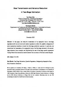
The statistical process governing the construction of particle histories is composed of two parts: the displacement sampling and the collision sampling. If the displacement does not result in the particle leaking out of the simulated space, a collision is sampled according to the properties of the medium. If the particle is not absorbed, a new displacement is sampled, and then another collision, etc. This process is shown in Figure 1.1.
Start of history
Flight length sampling
Transport
Leaving geometry
Inside geometry
Boundary condition
Collided nucleus sampling
Outgoing ~ and E Ω sampling
Interaction sampling
Scattering
Leakage
Absorption
End of history
Figure 1.1. Schematic representation of the simulation of a particle history using the Monte Carlo approach in a homogeneous medium.
26
1.2. MONTE CARLO RESOLUTION The probability density functions for displacement and collision are derived from the corresponding expressions of the displacement and collision kernels (Equation (1.5) and (1.6)). We present in the following the sampling laws obtained for a particle travelling in a homogeneous medium. As most of the simulated problems implies the simulation of heterogeneous geometries, the standard procedure for Monte Carlo particle transport simulations is to divide the simulated three-dimensional space into multiple volumes, each of which is assumed to be homogeneous. The process for particles that crosses boundaries between those volumes will be discussed at the end of this section. Flight length sampling Under the assumption that the transport is bounded to a single volume, the ~ Ω, ~ E), with X ~ inside the volume, depends only on cross section at any point (X, ~ 0 to the energy. Consequently, we have for the displacement kernel from point X ~ =X ~ 0 + xΩ: ~ point X � ~ 0 → X, ~ Ω, ~ E = Σt (E)e−xΣt (E) , D X
(1.14)
meaning that the distance x travelled by a particle between two interactions with the medium is exponentially distributed with a probability density function: f (x, E) = Σt (E)e−xΣt (E) 1x>0 ,
(1.15)
whose associated repartition function is: Z F (x, E) = 0
x
f (x0 , E)dx0 = [1 − e−xΣt (E) ]1x>0 .
(1.16)
Therefore, a particle displacement length can be sampled by sampling an uniformly distributed random variable ξ on the unit interval and using the inverse of F : 1 ln(1 − ξ). (1.17) x = F −1 (ξ, E) = − Σt (E) Collision sampling Once the particle has been moved a distance x in the direction Ω, a collision has to be sampled. The collision kernel from Equation (1.6) can be rewritten ~ 0 → Ω, ~ E 0 → E) = C(Ω
1 ~ 0 → Ω, ~ E 0 → E). Σs Ω Σt (E 0 )
(1.18)
A homogeneous medium is actually a homogeneous mixture of nuclides. The collision kernel can be expressed in terms of the total macroscopic cross sections
27
CHAPTER 1. MONTE CARLO PARTICLE TRANSPORT Σj,t of each nuclide j, and of the cross section of each interaction i, denoted for nuclide j by Σj,i : � � X Σj,t (E) X Σj,i (E) ~ 0 → Ω, ~ E0 → E , ~ 0 → Ω, ~ E0 → E = fj,i Ω C Ω Σt (E) i Σj,t (E) j
(1.19)
� ~ 0 → Ω, ~ E 0 → E is the probability density function of going from where fj,i Ω ~ 0 , E 0 ) to (Ω, ~ E) during a collision of type i on nuclide j. From this last formu(Ω lation, we derive the sampling procedure for the particle collision: - sampling of the nuclide which the particle collides with: the nuclide j is chosen with probability Σj,t (E) . (1.20) Pj = Σt (E) - sampling of the reaction type: the reaction i is selected from all reactions available for nuclide j with probability Pj,i =
Σj,i (E) σj,i (E) = . Σj,t (E) σj,t (E)
(1.21)
~ and energy E of the particle after the collision: - sampling of the direction Ω ~ 0 and energy E 0 of the particle those parameters depend on the direction Ω before the collision, and are distributed with the probability density function available in the nuclear data: � ~ 0 → Ω, ~ E0 → E . fj,i Ω
1.2.2
(1.22)
Case of geometry with multiple volumes
As discussed above, the geometry is most of the time divided into multiple volumes, each of which is assumed to be homogeneous. Various procedures for handling geometries consisting of multiple volumes can be found in [11]. The process described in the following has been selected because it presents some advantages for the further use of the Adaptive Multilevel Splitting technique, which will be discussed in Chapter 3. As long as the particles travel and interact inside a single volume, the transport process remains unchanged. However, it may also happen that a flight length sampled for a displacement causes the particle to change volume. In that case, the particle is placed at the boundary between the volumes, and a new flight length is sampled from this point, using the characteristics and cross sections
28
1.2. MONTE CARLO RESOLUTION of the new volume. The corresponding adapted transport scheme is shown in Figure 1.2. Start of history
Flight length sampling
Transport
New volume
Leaving volume
Inside volume
Moving to volume boundary
Collided nucleus sampling
Outgoing ~ and E Ω sampling
Interaction sampling
Scattering
Out of geometry Boundary condition Leakage
Absorption
End of history
Figure 1.2. Schematic representation of the simulation of a particle history using the Monte Carlo approach in multiple volumes.
1.2.3
Score definitions
The purpose of a fixed-point Monte Carlo simulation is to compute an estimate of a response function within an area of interest. This estimate is computed by counting particle-related events occurring in the area of interest, such as collisions or displacement lengths, to which we refer as ”contributions” to the estimation. We refer to the couple estimator/area of interest as a ”score”. There are many different scores that can be evaluated in Monte Carlo simulations. In the following, we present the most common responses and the associated estimators: the particle flux either in a volume or at a surface, the particle current and the reaction rates. One can compute multiple scores in a single Monte Carlo simulation: either various responses in the same area of interest (for example a particle flux in a detector and particle current at the detector’s boundary), or the same response in various locations (like a reaction rate estimated in multiple volumes).
29
CHAPTER 1. MONTE CARLO PARTICLE TRANSPORT Particle flux in a volume A particle flux is defined as the number of particles travelling through a unit area per unit time. It is therefore expressed in cm−2 s−1 . In fixed-point Monte Carlo simulations, it is common to disregard the time dependency of the problem. Most of the time, we assume that the particle sources emit one particle per second, and that the particle transport is instantaneous, thus obviating the time dependence in the simulation as well as in the result. There are two standard estimators that can be used to estimate the particle flux in a volume. The first one is the track-length estimator, which computes the score as the total distance travelled by the particles in the volume of interest (in cm), divided by the number of simulated particles and the volume of the detector area (in cm3 ): n 1 X ˆ li , (1.23) φTRACK = nV i=0 where n is the number of source particles, V the volume of the detector area and li the distance travelled by particle i in the volume of interest (which is therefore the ”contribution” of particle i to the score). The second estimator of the flux in a volume is the collision estimator, which estimates the particle flux by counting the number of collisions in the detector area and multiplying this value by the mean distance travelled by a particle between two collision points in the volume of interest, which is the multiplicative inverse of the total cross section in the detector. We have therefore n 1 X ci ˆ φCOLL = , nV i=0 Σt
(1.24)
where ci is the number of collisions undergone by particle i in the volume of interest, and Σt is the total cross section in the detector. The collision estimator is a priori less precise that the track-length estimator, especially in low-density media in which the collision probability is low. However, it is slightly simpler to compute, as it does not require to evaluate travelled distances between collisions and interfaces of volumes. This property can for example be interesting to estimate a flux in the cells of a mesh covering part of the geometry. Particle current and surface flux The estimator used to evaluate the particle current at a surface is simply the number of particles crossing the surface divided by the number of source particle
30
1.2. MONTE CARLO RESOLUTION and the surface area.
n
1 X JˆSURF = 1S (i), nA i=0
(1.25)
where 1S (i) is 1 if particle i crossed the surface, and zero otherwise. It is also possible to evaluate the particle flux through a surface, in which case the contribution of each particle crossing the surface is computed as the cosine of the angle between the particle direction and the normal vector of the surface: n
1 X 1S (i) φˆSURF = , ~ i~nS nA i=0 Ω
(1.26)
~ i denotes the direction of particle i at the crossing point and ~nS is the where Ω unit normal vector of the surface. Reaction rates The reaction rate is estimated in a volume as the average number of interactions taking place per cubic centimeter per second. It is computed as the product between the particle flux in the volume and the cross section of the reaction of interest. For reaction j (total, absorption, etc.), we have Rj = Σj φ,
(1.27)
and the associated Monte Carlo estimator: ˆ ˆ j = Σj φ, R where φˆ can be either the track-length or collision estimator of the flux.
31
(1.28)
CHAPTER 1. MONTE CARLO PARTICLE TRANSPORT
32
Chapter 2
Variance reduction techniques This chapter is devoted to the presentation of several variance reduction techniques. This description is not meant to be exhaustive, but rather focused on the methods implemented in the transport code TRIPOLI-4, around which this thesis work revolved. The purpose of this chapter is to introduce the state of the art, as a frame to help the reader understand the starting point of this Ph.D. work. To that end, the last section of this chapter consists in the presentation of the Adaptive Multilevel Splitting algorithm, in a formalism adapted to the simulation of discrete Markov chains. It should be noted however that the theoretical description made in this section is not a mandatory step to understand how the method works when applied to particle transport, which will be the main objective of Chapter 3.
2.1
Motivation
In a Monte Carlo particle transport simulation, the limiting factor is the number of histories that need to be simulated in order to get a result with a reasonably small confidence interval. In the case of radiation shielding simulations, we are interested in the simulation of rare events, whose occurrence probabilities are typically between 10−5 and 10−20 . Only a few simulated histories will therefore contribute to the response associated to such events, resulting in either a large statistical error on the result, or a very long computation time. Variance reduction methods were introduced in order to tackle this issue. They aim to alter the simulation process, in order to reduce the variance on the estimated score for a given computation time. In the following, we will refer to simulations without variance reduction as analog. There are three ways for a variance reduction technique to modify the simulation: - To control the particle population, by increasing/decreasing it in areas of high/low interest - To modify the occurrence probability of certain physical processes in order to increase the probability for a particle history to contribute to the score
33
CHAPTER 2. VARIANCE REDUCTION TECHNIQUES - To replace parts of the Monte Carlo simulation by deterministic calculations to improve the overall computation time Obviously, the modifications induced by the methods of the first two categories must be balanced in order to keep an unbiased estimation of the response. Indeed, a non-analog Monte Carlo simulation will hopefully provide many more contributions to the score than an analog simulation. This problem is addressed by assigning a so-called weight to the altered trajectories. The contribution of any weighted particle to the score will then be multiplied by the particle’s weight, thus ensuring that the simulation result remains unbiased.
2.2
Figure of merit
The efficiency of a variance reduction method is based on two quantities: the variance on the estimated result σ 2 , and the computation time t (CPU time). The variance, as the square of the standard deviation σ, varies with the inverse of the number of simulated histories n: σ2 ∼
1 . n
(2.1)
On the other hand, the computation time is directly proportional to n, provided that the number of simulated particles is large enough to smooth out the differences of computation time between two distinct particle trajectories. As a result, the product σ 2 × t is independent of the number of simulated particles, and can be used to compare the efficiency of two simulations. To this end, the figure of merit (or FOM) is defined as F OM =
1 , σ2t
(2.2)
as a measurement of the simulation efficiency. The higher the FOM, the greater the performances of the simulation.
2.3
Exponential Transform
The Exponential Transform [12], derived from the Exponential Biasing (or Importance Sampling), is the reference variance reduction method of the transport code TRIPOLI-4 [13]. It is based on the use of a so-called importance function, which is an arbitrary function associating any point of the phase space to an ~ Ω, ~ E) ∈ R, quantifying whether or not a particle located importance value I(X, ~ Ω, ~ E) is of interest to the simulation. The purpose of exponential at point (X, transform is to build a biased game, which means a stochastic process that has the same global behaviour as an analog simulation, but with different operators. We recall the linear Boltzmann equation satisfied by φ, in its integro-differen-
34
2.3. EXPONENTIAL TRANSFORM tial formulation (see Section 1.1.2):
ZZ
� � � ~ ∇φ ~ X, ~ Ω, ~ E + Σt X, ~ E φ X, ~ Ω, ~ E = Ω. � � 0 0 ~ Ω ~ 0 → Ω, ~ E 0 → E φ X, ~ dE + Q X, ~ Ω ~ 0 , E 0 dΩ ~ Ω, ~ E). Σs X,
(2.3)
We define the biased flux φ? such that for any point of the phase space, ~ Ω, ~ E) = I(X, ~ Ω, ~ E)φ(X, ~ Ω, ~ E). We can rewrite Equation (2.3) to get an φ (X, ? equation on φ : ?
~ ∇φ ~ ? X, ~ Ω, ~ E + Ω. �
ZZ
~ ~ ~ ~ E − Ω. ~ ∇I(X, Ω, E) Σt X, ~ Ω, ~ E) I(X, �
! � ~ Ω, ~ E = φ? X,
� 0 0 � ~ ~ ~ dE ~ Ω ~ 0 → Ω, ~ E 0 → E I(X, Ω, E) φ X, ~ Ω ~ 0 , E 0 dΩ Σs X, ~ Ω ~ 0, E 0) I(X,
(2.4)
~ Ω, ~ E)I(X, ~ Ω, ~ E). +Q X, ~ Ω, ~ E) of the phase space the following We now introduce for any point (X, quantities: ~0 = - Ω
~ X,E) ~ ∇I( , ~ ~ k∇I(X,E)k
~ E) = - κ(X,
~ X,E)| ~ |∇I( , ~ I(X,E)
~ Ω, ~ E) = Σt (X, ~ Ω, ~ E) − κ(X, ~ E)Ω. ~ Ω ~ 0, - Σ?t (X, ~ Ω ~ 0 → Ω, ~ E 0 → E) = - Σ?s (X,
~ I(X,E) ~ Ω ~0 Σ (X, ~ I(X,E 0 ) s
~ E 0 → E), → Ω,
which we then substitute in Equation (2.4) in order to obtain
ZZ
� � � ~ ∇φ ~ ? X, ~ Ω, ~ E + Σ?t X, ~ Ω, ~ E φ? X, ~ Ω, ~ E = Ω. � � 0 0 � ~ Ω ~ 0 → Ω, ~ E 0 → E φ? X, ~ Ω ~ 0 , E 0 dΩ ~ dE + I X, ~ Ω, ~ E Q X, ~ Ω, ~ E). Σ?s X,
(2.5) Equation (2.9) written in this manner has the same form as Equation (1.2). It is simply the linear Boltzmann equation, but with biased operators: Σ?t instead of Σt , Σ?s instead of Σs and I × Q instead of Q. The Exponential Transform method is restrained to the biasing of the displacement operator, while the collision sampling remains unchanged. This is obviously not optimal, but the collision biasing requires heavy implementation, while the
35
CHAPTER 2. VARIANCE REDUCTION TECHNIQUES displacement biasing simply consists in tampering with the displacement sam~ Ω~0 for pling procedure by substituting the biased cross section Σ?t = Σt − κΩ. ? the total cross section Σt . Since the parameter κ is always positive, Σt is smaller ~ 0 , and greater when than Σt when the particles have a direction oriented towards Ω they go in the opposite direction. Therefore, the flight lengths are stretched for the particles going in the direction of the importance gradient, and shortened for those directed the way opposite. Consequently, the particles are drawn towards the areas of greater importance, thus helping the simulated particles to reach areas of interest if the importance function I is well-defined. The response associated to the biased flux is, according to Equation (1.12), Z
?
R (D) = ~ Ω,E)∈D ~ (X,
Z = ~ Ω,E)∈D ~ (X,
� � ~ Ω, ~ E φ? X, ~ Ω, ~ E dXd ~ ΩdE ~ gR? X, � � � ~ Ω, ~ E φ X, ~ Ω, ~ E I X, ~ E dXd ~ ΩdE. ~ gR? X,
(2.6)
Since the response estimated using the biased game should be the same as the response estimated with an analog simulation, we have
gR?
� ~ ~ g R X, Ω, E ~ Ω, ~ E = X, � . ~ E I X, �
(2.7)
In other terms, every contribution to the score obtained during the biased simulation should be weighted by a factor wET =
1 �, ~ I X, E
(2.8)
which is handled in practice by the corrective weights of the particles. The choice of an appropriate importance function lies at the heart of the exponential transform method. There are multiple ways to obtain an importance function. The most interesting candidate however is the solution of the adjoint equation [4, 10]:
ZZ
� � � ~ ∇φ ~ † X, ~ Ω, ~ E + Σt X, ~ E φ† X, ~ Ω, ~ E = −Ω. � � 0 0 ~ Ω ~ →Ω ~ 0 , E → E 0 φ† X, ~ Ω ~ 0 , E 0 dΩ ~ dE + Q† X, ~ Ω, ~ E). Σs X,
(2.9)
where Q† is the adjoint source of the problem (related to the detector response). The solution φ† of this equation is called the adjoint flux, which is for any given
36
2.4. IMPLICIT CAPTURE point of the phase space the average flux that would be generated by a particle placed at this location. It can be shown that if the adjoint flux is used as importance function, the variance on the associated flux estimate is zero or nearly zero whatever the number of simulated particles. In any case, the computation of the adjoint flux is a problem at least as complex as the resolution of the direct equation. However, using an approximation of the adjoint flux as importance function for the Exponential Transport method may be sufficient to efficiently reduce the variance without requiring the simulation of too large a number of particle histories. In this view, TRIPOLI-4 has a module called INIPOND that automatically pre-computes an importance map to be used during the biased simulation [14]. INIPOND approximates the adjoint flux on a discretized space and energy mesh, by using an analogy with a one-dimensional problem. This module and the importance map it generates will be used and discussed in Chapter 3.
2.4
Implicit capture
One of the possible causes of rare events is the presence of a highly absorbing material in the simulated space. Indeed, a simulated particle entering such a material has a low probability of ever coming out. It can therefore be interesting to reduce the probability for a simulated trajectory to end in a capture, and rather let the associated particle explore the geometry further. This can be done using implicit capture. Implicit capture simply consists in replacing capture events (and more generally absorption events) by scattering events. The corrective weight associated to the implicit capture is the non-absorption probability associated to the collided nucleus. The weight of a particle entering a collision on a nucleus j at point P has to be multiplied by a factor wIC = 1 −
σj,s σj,a = , σj,t σj,t
(2.10)
where σj,a is the microscopic absorption cross section for nucleus j, and σj,s its microscopic scattering cross section. The removal of all the absorption processes allows for longer particle trajectories, but then no event can be sampled to stop the particles transport except for the leakage out of the geometry or of the energetic domain of simulation. Therefore, the implicit capture has to be associated with another method capable of ending the particle histories. This can be done using weight control methods [15].
2.5
Weight control
The purpose of weight control is to limit the discrepancies in the weight distribution among the particles. Whenever weights are introduced in a Monte Carlo
37
CHAPTER 2. VARIANCE REDUCTION TECHNIQUES simulation, the danger of having big discrepancies in the particle weight values arises. If the weight of a particle becomes insignificant compared to the average contribution to the score, the computational resources spent to simulate the transport of this particle may be considered as a waste. On the other hand, if a particle happens to contribute to the score with a far greater weight than any other, the estimation of the score and its variance becomes unstable, due to a single contribution carrying most of the score. The splitting and Russian roulette mechanisms are the most commonly used tools to address these issues [10, 16]. Splitting is used to reduce the weight of particles, while Russian roulette prevents them from dropping too low.
2.5.1
Splitting
The principle of the splitting technique [1] is to split a particle of weight w into n distinct particles, each carrying a weight wj , j ∈ [1, n] such that n X
wj = w,
(2.11)
j=1
in order to have a better exploration of the geometry while keeping the global simulated weight constant. In practice, the use of splitting in Monte Carlo transport simulation is not restrained to weight control. However, as the particles generated by splitting carry only a fraction of their precursor’s weight, splitting can be used to prevent the particles weights from diverging. In that case, a threshold weight wmax is defined, as well as a splitting number n. Whenever a particle weight w becomes greater than wmax , the corresponding particle is instantaneously split into n particles, each carrying one n-th of the initial weight w. A wider exploration of the phase space should help reduce the variance, but the multiplication of the particles implies an increase in computation time. Nonetheless, a wise choice of the splitting parameters should allow for a significant increase of the FOM.
2.5.2
Russian roulette
The Russian roulette [10, 16] aims at limiting the lifespan of particles that are unlikely to yield a relevant contribution to the final score. It can therefore be used as a weight control technique to stop the transport of particles carrying a small weight. Similarly as for the splitting technique, a threshold weight wmin has to be defined. When the weight of a particle becomes lower than wmin , a random game
38
2.6. ADAPTIVE MULTILEVEL SPLITTING is played to decide whether or not the particle is killed. Any particle of weight w ≤ wmin is killed by the Russian roulette with probability Pkill = 1 − w.
(2.12)
If the particle does survive the roulette, its weight is set to 1 in order to keep the average particle weight equal to the particle weight before the triggering of Russian roulette. In a more general setting, a survival weight ws > wmin can be defined for the roulette, in which case the probability Pkill becomes Pkill = 1 −
w , ws
(2.13)
the weight of the surviving particles being set to ws instead of 1.
2.6
Adaptive Multilevel Splitting
A new variance reduction method has recently been proposed in the literature of applied mathematics [2]. Originally designed to help the simulation of rare events associated to continuous Markov chains, it has been extended to discrete Markov chains [3]. Consequently, there will be no mention of particles in this section, whose purpose is to present a general theoretical setting of the AMS algorithm. We present in this section the mathematical setting of the AMS algorithm applied to discrete Markov chains, which is the most suitable version of the AMS algorithm in view of a transposition to the field of particle transport. This choice will be justified in Chapter 3 alongside the description of the practical implementation of AMS as a variance reduction method for Monte Carlo particle transport. It should however be kept in mind that the version of the AMS presented in this section fits perfectly the theoretical framework of [3], so that the estimator of the rare event occurrence probability introduced in the following is unbiased. The following description is extracted from an article written as part of this Ph.D. and presented at the joint conference International Conference on Radiation Shielding / Topical Meeting of the Radiation Protection and Shielding Division of the American Nuclear Society (ICRS-13 & RPSD-2016) [17].
2.6.1
Objective and setup
Let X = (Xt )t∈N be a discrete-time Markov chain with values in Rd , d ∈ N∗ . We define P as the path space, containing all possible realisations of the Markov chain X. Given D a subset of Rd , we define the entrance time of the Markov chain X in D: τD = inf{t ∈ [0; τf ] : Xt ∈ D}, (2.14) 39
CHAPTER 2. VARIANCE REDUCTION TECHNIQUES where τf is the final stopping time of the Markov chain X, which we suppose almost surely finite. Given an observable φD : P → R such that φD (X) = 0 on the event τf < τD , we would like to estimate the average E(φD (X)) of φD . Let us suppose now that the probability for (Xt ) to enter D before τf is very small, i.e. P(τD < τf ) � 1. Estimating E(φD (X)) requires to sample the rare event τD < τf . In such a case of rare event simulation, the AMS algorithm proposes to reduce the variance of the estimation of E(φD (X)) by increasing the number of Markov chains reaching the subset D. AMS is an iterative algorithm that consists of several steps. The first step is a basic Monte Carlo simulation of multiple replicas of the Markov chain X with a given initial condition. Each of the following steps consists in the resampling of some Markov chains among the replicas, with an initial condition getting closer to D at each iteration of the algorithm.
2.6.2
The AMS algorithm
Importance function We define a so-called importance function, mapping Rd to R: ξ : Rd → R, which is used to quantify the proximity of a point in Rd to the subset of interest D. The only requirement on ξ is that there exists a constant Zmax ∈ R such that ξ(x) ≥ Zmax if x ∈ D.
(2.15)
We further define the importance of a realization X = (Xt )t∈N of the Markov chain as the supremum of ξ along the chain: I(X) = sup ξ(Xt ).
(2.16)
t∈[0;τf ]
The ξ function is probably the most important ingredient of the AMS algorithm, since it is used to quantify the proximity of a path to the subset D. It is therefore important to choose a good function ξ with regards to the rare event we are trying to simulate. Even if the AMS algorithm is proven to yield an unbiased result regardless of ξ, the choice of an optimized importance function is expected to improve the variance reduction efficiency.
40
2.6. ADAPTIVE MULTILEVEL SPLITTING Initialization The AMS algorithm consists in an evolving interacting system of weighted replicas. Given n > 0, we simulate n i.i.d. replicas of the Markov chain X, denoted j j by X0j = (X0,t )t∈N , j ∈ {1, . . . , n}. For all j, the initial state X0,0 is a point x0 located outside D. We define Z0 as Z0 = ξ(x0 ).
(2.17)
Let us denote by q ∈ N the current iteration number, and by k the number of replicas to be resampled at each iteration.Within an iteration of the AMS algorithm, every replica has the same weight. The common weight at iteration q will be denoted wq , with w0 set to 1. For the sake of simplicity, we assume in the following that distinct paths cannot have the same importance. The general case is discussed in Section 2.6.3. Now we can start iterating on q ≥ 0. Iterations j 1. For each j ∈ {1, . . . , n}, denote by τq,f the stopping time of the Markov j j chain Xq , and by Sq its importance (See Equation (2.16)):
Sqj = I(Xqj ).
(2.18)
2. Sort the sample (Sq1 , . . . , Sqn ) in increasing order: Sq(1) < . . . < Sq(k) < . . . < Sq(n) . (k)
3. Denote by Zq+1 the k -th order statistics Sq : Zq+1 := Sq(k) .
(2.19)
4. If Zq+1 ≥ Zmax , stop iterating, set Q = q and go to the final step (j)
5. For all j ∈ {1, . . . , k}, resample replica Xq according to the resampling j kernel described in the following, and denote it by Xq+1 (j)
j 6. For all j ∈ {k + 1, . . . , n}, define Xq+1 = Xq
7. Update the common weight: wq+1 =
41
n−k wq . n
(2.20)
CHAPTER 2. VARIANCE REDUCTION TECHNIQUES 8. Increment q and go to step 1. Resampling process At each iteration of the AMS algorithm, k replicas are resampled. Let us denote the current iteration number by q and the associated resampling level by Zq+1 . For each of the k replicas X (j) , j ∈ {1, . . . , k} to be resampled, one of the remaining replica X (i) , i > k is randomly selected for duplication. We know for sure (i) that the Markov chain (Xt )t∈[0;τ (i) ] contains at least one state whose importance f
is greater than Zq+1 (otherwise it would have been resampled). We can therefore define n o (i) (i) τq(i) = inf t ∈ [0; τq,f ] : ξ(Xq,t ) > Zq+1 (2.21) as the first time at which the replica X (i) has an importance greater than Zq+1 . (i) (i) The resampled Markov chain (Yt )t≥0 is defined as a copy of Xq,t for all t ∈ [0, τq ], and is then completed independently using the original Markov kernel, up to the stopping time τf . This resampled Markov chain replaces the original one X (j) for the next iteration of AMS. Final step Once the algorithm stops iterating, Q is the number of completed iterations. Given the bounded observable φD introduced in Section 2.6.1, we define φˆD such as n wQ X φD (XNj ). (2.22) φˆD = n j=1 Since the algorithm described in this section and the construction of φˆ fit the theoretical framework of a Generalized Adaptive Multilevel Splitting algorithm, we can apply Theorem˜4.1 of [3] (the ”unbiasedness theorem”), which states that E(φˆD ) = E(φD (X)),
(2.23)
so that φˆD is an unbiased estimator of E(φD (X)).
2.6.3
Interpretation of the replicas weights
In this section we provide a practical interpretation of the AMS weights to give an intuition on the estimator Equation (6.6). The mathematical proofs of the unbiasedness and consistency of the AMS estimator are not presented here. We refer the reader to [2] and [3] for theoretical support. At each iteration q ≥ 0, the level Zq+1 is chosen in such a way that the probability for a path Xqj to have an importance greater than Zq+1 (i.e. P(Sqj ≥ Zq+1 |Sqj ≥ 42
2.6. ADAPTIVE MULTILEVEL SPLITTING Zq )) is estimated by pˆq = 1 −
k . n
(2.24)
Keeping that in mind, we can see that the weights of the replicas at iteration j ≥ Zq+1 ). q + 1 are nothing more than an estimate of the probability P(Sq+1 In other words, the AMS algorithm provides us at each iteration q with a set of paths Xqj , j ∈ {1, . . . , n}, carrying a common weight, which can be interpreted as an estimate of the probability to have this particular set of paths instead of the paths sampled at iteration 0.
2.6.4
About the number of resampled replicas
The algorithm presented in Section 2.6.2 is an ideal case. In reality, it may occur that multiple replicas have the same importance. In that case, k should not be seen as the number of resampled replicas, but rather as the parameter which defines the splitting levels. Indeed, the number of replicas having an importance less or equal to the k-th lowest importance may very well be greater than k. When such a situation arises, every path whose importance is less or equal to the level has to be resampled [3]. This modification has to be taken into account in the replicas weights. If the current iteration is the q-th and the number of particles to be resampled is Kq ≥ k, then the weight update at step 7 of the algorithm has to be changed to: wq+1 =
n − Kq wq . n
(2.25)
In some pathological configurations, all the replicas may happen to have the same importance, which leads to extinction at the next iteration. In such a case, the iterating process is interrupted and the algorithm goes straight to the final step (See Section 2.6.2), eventually yielding a null contribution.
43
CHAPTER 2. VARIANCE REDUCTION TECHNIQUES
44
Part II Adaptive Multilevel Splitting for Monte Carlo particle transport
45
Chapter 3
Adaptation of the AMS algorithm to particle transport Every Monte Carlo transport code relies on the particle tracking routine, which simulates the random trajectories of the particles by transporting them from one interaction to another, until they are absorbed or leak out of the geometry. The purpose of this chapter is to introduce AMS to the field of particle transport, and show that it can be used as an effective variance reduction technique in this new context. To do so, we first present a practical reformulation of the AMS algorithm that takes the notions of particles and particle tracks into account. In a second part, we introduce the MENHIR prototype, a simplified Monte Carlo simulation code that was specifically designed to test the AMS implementation in the context of particle transport. The last section of this chapter is devoted to the presentation and analysis of some of the results obtained with MENHIR.
3.1
Applicability of AMS to particle transport
As described in Section 1.2, the simulation process of particle transport is such that at any given time in the particle life, the position and characteristics of the next interaction can be determined using only the particles coordinates (position, direction, energy) and the medium properties. This implies that the random process of particle transport can be seen as a discrete-time markovian process. Let us refer to the sequence of the phase-space coordinates of a particle (namely position, direction and energy) at each interaction with the medium as the particle’s track. During the transport, the track of each transported particle is built step by step, one interaction after the other, using only the knowledge available from the last point of the track. The particle tracks are therefore Markov chains, so that the AMS algorithm described in Section 2.6.2 can be implemented.
47
CHAPTER 3. ADAPTATION OF THE AMS ALGORITHM TO PARTICLE TRANSPORT We mentioned in Section 2.6 the existence of several versions of the AMS algorithm. Indeed, the AMS algorithm we presented in Section 2.6.2 can be adapted to handle continuous Markov chains (which is actually its original framework). Particle trajectories can very well be considered as continuous Markov processes, since a particle transport can be stopped and resumed even between collision points. However, the use of the continuous version of AMS is troublesome in our case for two reasons: on the one hand, it requires to evaluate particle importances continuously between collision points, which complicates the computation process if the importance function is nonlinear. On the other hand, the collision sampling process implies brutal changes of direction and energy at collision points, which may induces discontinuities in the importance along the particle trajectory for angular and/or energy dependent importance functions. Using the discrete formulation of AMS however, the importance of a particle trajectory can easily be computed by evaluating the particle importance at each collision point.
3.2
Practical AMS formulation
In the context of particle transport, the initialization step of the AMS algorithm consists in the analog simulation of a set of independent particles. Then, the AMS algorithm starts iterating until the stopping criterion is met. Each AMS iteration consists in two steps: first, the set of particles is sorted with regard to the particle importances (See Section 3.2.1). Then, the lowest-rated particles are resampled by splitting the other tracks as described in Section 3.2.2. The parameter k that is used to define the splitting level is defined before the first iteration and remains constant throughout the simulation. In Monte-Carlo particle transport simulations, the particles are usually gathered into batches, which are simulated one after the other. The mean score is computed as the empirical mean of the scores of each batch, and the associated standard error σ as the standard deviation of the batch scores divided by the square root of the number of batches minus 1. By analogy to other simulations, we will refer to an entire AMS simulation (initialization+iterations+final step) as a batch, so that the mean score is computed as the empirical mean of the AMS estimations of each batch.
3.2.1
The sorting step
Importance functions In order to use the AMS algorithm, one has to be able to determine which regions of the geometry are of interest to the simulation. Therefore, an importance function has to be associated to the geometry. This function maps any point of the phase space to an importance value, related to the probability for a particle
48
3.2. PRACTICAL AMS FORMULATION located at a given point P to contribute to the final score. We denote it by ~ Ω, ~ E), I(P ) = I(X,
(3.1)
~ Ω ~ and E are the position, direction and energy of the point P , respecwhere X, tively. It has to be noted that within AMS, this function is only used to rank the particles with respect to one another, so that the value of the importance at a given point does not need to be meaningful on its own. This property is one of the strengths of the AMS algorithm, as it allows for the use of trivial importance functions for any problem, such as the inverse of the distance to the area of interest. It is believed (although up to now without any theoretical proof), that the adjoint score of the problem is the most efficient importance function for AMS. The adjoint score at a given point of the phase space is defined as the average score generated in the area of interest by a particle emitted from this point. Therefore, it gives the most precise indication concerning the interest of a particle located at a given point with regards to the score. However, the determination of the adjoint score is a problem at least as complex as the estimation of the direct score. Furthermore, if one has access to the adjoint score, the solution of the direct problem is directly available as the value of the adjoint score at the source point, obviating the need to perform the simulation in the first place. As the AMS is robust with regards to the imperfections of the importance map, an approximation of the adjoint score seems to be a good importance function candidate for the AMS algorithm. Particle tracks importance In order to sort the particles, a value of importance has to be attached to each of the particle tracks. When a new particle is simulated, a track is created. We ~ 0, Ω ~ 0 , E0 ) the emission point of a particle, and the first point denote by P0 = (X of its track. This particle travels along straight lines between collisions with the medium, each collision resulting either in the absorption of the particle or in a scattering event resulting in a random change of the particle direction and energy. If the particle undergoes N collisions before being absorbed or leaking out of the geometry, we define its track T as follows: T = (P0 , . . . , PN ),
(3.2)
~ i, Ω ~ i , Ei ) represents the properties of the particle outgoing its i-th where Pi = (X collision with the medium. Using these notations, we introduce the importance
49
CHAPTER 3. ADAPTATION OF THE AMS ALGORITHM TO PARTICLE TRANSPORT of a particle track as: I(T ) = max I(Pi ).
(3.3)
i∈[0,N ]
We show in Figure 3.1 a particle track T . In this example, we assume that the importance of a point is given by its abscissa x. Therefore, the track importance I(T ) is that of the rightmost point. P4 ×
P0 ×
P3 +
+ P1
+ P2 x I(P0 )
I(T )
Figure 3.1. Illustration of a particle track and associated importance.
Importance function requirement Theoretically, there is only one requirement on the importance function (Equation (2.15)). We designed a trick to ensure that this requirement is always met whatever the importance function: any point within the area of interest is given a numerical infinite importance. Furthermore, when a particle enters the area of interest, the entry point is retrieved and appended to the particle track, also with infinite importance). Thus, if a particle goes through the area of interest without colliding in it, it would still have an infinite importance and would never be resampled. With this technique, if a particle that reached the area of interest is selected for duplication, the splitting takes place at the boundary and not inside the area of interest, which means that the contribution of the selected track has not to be duplicated (since the particles outside the area of interest do not contribute to the score). Definition of the splitting level Let n be the number of simulated particles, k the minimum number of tracks to be resampled per iteration and q the index of the current iteration. After the n particles have been absorbed or have leaked out of the geometry, the AMS algorithm computes the importance I(Tj ), j ∈ [1, n] of each particle track (see Equation (3.3)). The splitting level Zq is then defined as the k-th smallest value in the sample (I(T1 ), . . . , I(Tn )). Each particle track having an importance less or equal to Zq is deleted, and the number Kq of suppressed
50
3.2. PRACTICAL AMS FORMULATION particles at this iteration is kept in memory. Kq is by construction larger than k, and could be strictly larger if multiple tracks have the same importance.
3.2.2
The splitting step
Resampling process Once the sorting step of iteration q is over, the AMS proceeds to the resampling of the Kq particle tracks that have been deleted from the simulation, so that n distinct tracks are available for the next iteration of the algorithm. For each of the particles to be resampled, one of the n − Kq remaining tracks is selected. The probability distribution for the choice of the track to duplicate is uniform and with replacement. Let us denote by Tj = (Pi ), i ∈ [0, Nj ] one of the selected tracks. The emission point Psplit of the new particle is then defined as: Psplit = inf {i ∈ [0, Nj ] : I(Pi ) > Zq } ,
(3.4)
which is the first point of the track Tj having an importance strictly greater than Zq . The resampled particle is simulated from the point Psplit , and a new track is filled with its collision points. AMS global weight The resampling process splits Kq particle tracks among a set of n − Kq tracks, therefore all particles weights have to be weighted at the end of iteration q by a factor Kq (3.5) Wq = 1 − n to ensure unbiasedness [2, 3]. In practice, the cumulated weight factor due to the AMS process from iterations 1 to q is the same for each particle, and can be stored in a global weight
wq =
q Y
Wi
i=1 q Y Ki = (1 − ). n i=1
3.2.3
(3.6)
Scoring step
The AMS algorithm stops at the end of iteration q if n − Kq + 1 particles have reach the area of interest (i.e. Zq+1 is equal to numerical infinite). An estimator can be constructed for any score φ in the area of interest. If we denote by φˆM C
51
CHAPTER 3. ADAPTATION OF THE AMS ALGORITHM TO PARTICLE TRANSPORT the value estimated using a standard Monte Carlo estimator, then φˆAM S = wq × φˆM C
(3.7)
is an unbiased estimator of the quantity E(φ(X)) [3].
3.2.4
Optimization
Crossing points Most of the time, the geometries considered are composed of many regions, each of these regions having specific properties that impact the particle transport (travel length, collision probabilities,...). When a particle passes from one region to another during a flight, it can be stopped as it crosses the interface between the regions, and a new flight length is resampled from this crossing point, taking into account the properties of the entered region. In that case, the characteristics of the particle at the crossing point depend only on the coordinates of the particle at the last collision point and on the physical properties of the first region. Similarly, the next collision point can be determined based solely on the coordinates of the particle at the crossing point and the physical properties of the second region. Consequently, if the crossing points are added to the particle track in the same manner as real collision points, the enriched track remains a Markov chain. The AMS can thus be used on the enriched tracks [3]. This allows for a more precise estimation of tracks importances, as it adds an importance estimation between some collision points without any additional computing. This property can also be used to improve the knowledge of the track importance within a single volume by adding virtual surfaces in it (or simply by dividing it in sub-volumes). Track storage One of the downsides of the AMS algorithm is that it requires a priori to keep the particle tracks accessible in memory at all times. However, it is not mandatory for the algorithm to store every point of the tracks. The points composing the tracks are used in two ways during the AMS iterations: - To compute the importance of the track - To define the splitting points during the resampling process In order to avoid going through the importances of all points composing a track to find the maximum value and define the importance of the track, an
52
3.3. THE MENHIR PROTOTYPE importance value can be assigned to each particle before their transport. Each time a point is added to the particle’s track, the previous particle importance is compared to the new point importance, and updated if necessary. By means of the particle importance, there is no more need to keep every collision points in the track in order to compute the track importance. Furthermore, we can see that according to Equation (3.4), the splitting point on a given track is defined as the first point of the track which importance is greater than the current AMS splitting level. This means that the only points that may be chosen for splitting are those having an importance greater than any preceding point on the track. There is consequently no need to store a point in the track if the point importance is less than the importance the particle had when reaching it. In the following implementations of the AMS algorithm, the tracks will only contain points of increasing importance, and the importance of the tracks will be computed on the fly. Parallelization Since a Monte Carlo particle transport simulation is made of a large number of independent batch simulations, the standard parallelization of such codes is simply performed by running batches in parallel while a collector thread manages the gathering of each thread’s results. This procedure can be optimized by sharing data concerning the geometry, materials, and other global variables. Concerning AMS for particle transport, a straightforward way of parallelizing the calculations is to run independent AMS simulations on distinct threads, each handling alone the initialization, iterations and final step. One may consider other options to parallelize AMS calculations, like using multiple threads at each resampling step to transport simultaneously all new replicas. However, since simulations using the AMS algorithm still require to perform multiple independent batch simulations, no options appears to be more efficient than to run the batches on distinct threads and collect the estimations of each batch afterwards to compute the average result.
3.3
The MENHIR prototype
In order to test the feasibility of implementing the AMS algorithm in a particle transport code, we decided to use a toy model depicting a geometry in which analytical reference results can easily be computed. The problem consists in an isotropic source of monoenergetic particles within an infinite homogeneous medium. The source is placed at the centre of a spherical shell in which the particle flux is estimated. A simplified Monte Carlo transport prototype, called MENHIR, has been developed to simulate this problem. MENHIR has been specifically designed for AMS testing, allowing for an easy implementation and validation of the algorithm.
53
CHAPTER 3. ADAPTATION OF THE AMS ALGORITHM TO PARTICLE TRANSPORT
Figure 3.2. MENHIR geometry.
3.3.1
Physics
The physics simulated in MENHIR is very simplified.The transported particles are monoenergetic. They travel at constant speed and undergo only two types of collision: absorption and isotropic scattering. As the medium composing the geometry is homogeneous, the absorption and scattering events occur with constant probability rates. The associated cross sections are denoted Σa and Σs , such that Σt = Σa + Σs . (3.8) When a particle is absorbed, transport is over and the particle’s history is terminated. On the other hand, a particle undergoing a scattering event remains alive but changes direction at random. The angular distribution of particles outgoing a scatter is isotropic. These assumptions allow for an easy prototyping of the AMS algorithm. Furthermore, the flux in the target shell can be analytically computed, which provides a reference value to validate the AMS implementation. Details concerning the computation of the analytical solution can be found in Appendix A.
3.3.2
Code structure
MENHIR is written in C++. It is composed of 6 files, accounting for roughly 1100 lines of code. MENHIR is object oriented and divided into 4 classes: Point, Vector, Geometry and Particle. - The Point and Vector classes are basic classes containing three-dimensional coordinates, as well as methods returning for example the distance of a given point to the source, the norm of a vector, sampling methods to generate isotropic vectors, etc. - The Geometry class handles cross sections, sampling procedures for the
54
3.3. THE MENHIR PROTOTYPE flight length and collision type as well as methods computing importance values. - The Particle class holds everything relevant to a given particle: coordinates, track, as well as the method that determines the position of splitting points. MENHIR is capable of performing both analog and AMS simulations. The code is executed using a simple command line, in which the simulation parameters can be modified. The particle source point is fixed and always located at the origin of the coordinate system (0, 0, 0). The free parameters of the simulation are: - The simulation type (AMS or ANALOG) - The total cross section Σt (in cm−1 ) - The scattering probability
Σs Σt
∈ [0; 1[
- The distance between the source point and the target shell - The thickness of the target shell - The number of batches - The number of particles per batch - The minimum proportion of deleted particles by iteration (AMS only) - The importance function to be used for tracks classification (AMS only)
3.3.3
Transport process
Before presenting and discussing the results obtained using MENHIR with various parametrizations, we describe here the particle transport and the AMS process within MENHIR. The pseudo-code for the analog transport process can be found in Algorithm 1. A particle is emitted at point (0, 0, 0) with an isotropically sampled direction ~ A flight length d is sampled from the exponential distribution of parameter Σt . Ω. If this flight length is long enough for the particle to cross the boundary of the target shell, the particle is moved to the shell’s boundary and a new flight length ~ to is sampled. Otherwise, the particle is moved of distance d in the direction Ω, the location of its first collision site. The particle is absorbed with probability ΣΣat . If it is not absorbed, the particle is scattered towards a new isotropically sampled direction. The process is repeated until the particle is absorbed. In a similar way as for the particles entering the target shell, if the flight length of a particle within the shell is long enough for the particle to exit the shell, the particle is moved to the exterior boundary, and a new flight length is sampled from here. The consideration of such interface crossing points allows for an easy scoring of the track estimator: the particle tracks that contribute to the
55
CHAPTER 3. ADAPTATION OF THE AMS ALGORITHM TO PARTICLE TRANSPORT flux are actually already divided into parts that are either completely within the shell or completely out of it.
Algorithm 1: Pseudo-code for analog particle transport in MENHIR. 1 while particle is alive do 2 sample flight length; 3 if entering or leaving target shell then 4 move particle to target boundary ; 5 if leaving then update track length estimator ; 6 else 7 move particle to collision site ; 8 if collision in target shell then 9 update track length estimator ; 10 update collision estimator ; 11 end 12 solve collision; 13 end 14 end The particle transport process in the case of an AMS simulation is only altered by the storing of the particle tracks and the computation of the track importances, and remains otherwise unchanged. The entry points of particles in the target shell are given a numerically infinite importance so as to ensure that the requirement on the importance function is met (see Equation (2.15) and Section 3.2.1). In practice, MENHIR sets this importance to DBL MAX, which is in C and C++ the value of maximum representable finite floating-point number and depends on the system and compiler used. On our system, DBL MAX= 1.797 69e308. MENHIR takes into account the considerations described in Section 3.2.4: the importance of each track is computed on the fly, and only the points of increasing importance are added to the particle track. The pseudo-code describing the particle transport for AMS simulations in MENHIR is shown in Algorithm 2.
3.3.4
AMS iteration process
When MENHIR uses the AMS algorithm, the code starts iterating after the initial simulation of n particles. The pseudo-code of the AMS iteration process is shown in Algorithm 3. At the end of the initial simulation, the importances of the n generated tracks are ordered, so as to find the k-th smallest value which will be our first splitting level Z. In order to be efficient in the particle classification, the vector containing the track importances is only partially sorted, making use of the C++ nth element function with parameter k, which rearranges the elements of the
56
3.3. THE MENHIR PROTOTYPE Algorithm 2: Pseudo-code for AMS particle transport in MENHIR. 1 Itrack := 0 ; 2 while particle is alive do 3 sample flight length; 4 if entering target shell then 5 move particle to target boundary ; 6 set Ipoint ←DBL MAX ; 7 if leaving target shell then 8 move particle to target boundary ; 9 update track length estimator ; 10 else 11 move particle to collision site ; 12 if collision in target shell then 13 update track length estimator ; 14 update collision estimator ; 15 end 16 solve collision; 17 get Ipoint as the importance after collision; 18 end 19 if Ipoint > Itrack then 20 add point to particle track; 21 update Itrack ← Ipoint ; 22 end 23 end
vector in such a way that the element at the k-th position is the element that would be in that position if the vector was entirely sorted [18]. Once the splitting level Z is obtained, the tracks are separated into two vectors: the rejected and the survivors vectors, according to whether or not the importance of the track is greater than the splitting level. The global weight W , which is set to 1 before the first AMS iteration, is multiplied by (1 − Kn ), where K is the size of the rejected vector. Each of the tracks within the rejected vector is then resampled according to the resampling process described in Section 3.2.2, by randomly selecting and duplicating a track from the survivors vector, and sampling a new track using the transport process presented in Section 3.3.3. When the K rejected tracks have been resampled, the new splitting level Z is computed, and if Z is less than DBL MAX, another iteration begins. Otherwise, the AMS algorithm stops iterating, and the cumulated estimators of the flux are weighted by W before the simulation ends.
57
CHAPTER 3. ADAPTATION OF THE AMS ALGORITHM TO PARTICLE TRANSPORT Algorithm 3: Pseudo-code for AMS iterations in MENHIR. 1 q := 1 ; 2 W := 1 ; 3 Z := kth element(I(T1 ), . . . , I(Tn )) ; 4 while Z ≤ DBL MAX do 5 K := 0 ; 6 empty rejected and survivors vectors ; 7 for i ∈ [1, n] do 8 if I(Ti ) ≤ Z then 9 add i to rejected vector; 10 K ←K +1 11 else 12 add i to survivors vector; 13 end 14 end 15 W ← W × (1 − Kn ) ; 16 for j in rejected vector do 17 randomly select a track l from the survivors vector ; 18 determine the splitting point on Tl ; 19 sample a new track Tj from the splitting point ; 20 end 21 q ←q+1 ; 22 Z ← kth element(I(T1 ), . . . , I(Tn )) ; 23 end
3.3.5
Importance functions
Within MENHIR, three importance functions are available for AMS use. We denote them Id , Ia and Ix . They are described in the following, and shown in Figure 3.3. Distance importance function Id In our geometry, a straightforward way of defining an importance is to use a function that increases as the distance to the target shell decreases. This can be achieved for example by using the distance to the source point. For a spatial ~ = (x, y, z), the distance to the source point (0, 0, 0) is: point X dsource =
p
x2 + y 2 + z 2 .
(3.9)
As it has already been stressed before, the AMS uses the importance function only to classify particles, therefore the simulation remains unchanged if the importance is replaced by any function having the same level sets. This is why we can get rid of the square root without impacting the AMS behaviour. We then
58
3.3. THE MENHIR PROTOTYPE
Figure 3.3. Illustration of importance functions in MENHIR. define Id by
~ = x2 + y 2 + z 2 . Id (X)
(3.10)
Angular importance Ia The importance function Id , as defined in Equation (3.10), does not take into account the direction of the particles. However, it seems natural that two particles located at equal distance to the target shell should have different importances if one is going straight towards the target, and the other one in the opposite direction. In order to have a more precise definition of the importance, we try and build an importance function that depends on the angular coordinates. Due to the homogeneity of the medium and also the fact that all scattering events are isotropic, a pertinent classification can be obtained using Id for two particles before collision. Keeping that in mind, an angular importance function can be derived for a particle after collision by estimating the position of the next collision from the current position and direction of the particle. As the flight lengths are exponentially distributed with parameter Σt , the mean free path of a particle in the geometry ~ Ω) ~ as is 1/Σt . Therefore, we define the angular importance of any point (X, � � 1 ~ . ~ Ω) ~ = Id X ~ + Ω Ia (X, Σt
(3.11)
X-Importance Ix In order to test the robustness of the AMS algorithm, which should be able to provide an unbiased estimation of the flux whatever the importance function,
59
CHAPTER 3. ADAPTATION OF THE AMS ALGORITHM TO PARTICLE TRANSPORT we also test a ”bad” importance function, i.e. a function that does not accurately represent the problem at hand. In this view, MENHIR can use the coordinate x as an importance function: ~ = x. Ix (X) (3.12) The use of Ix as importance function for the AMS algorithm is obviously not optimal, as it prevents the duplication of particle tracks having points with negative x coordinates. The contributions of such particles can therefore only be taken into account if they reach the detector directly from the source in the initialization phase of the AMS algorithm.
3.4 Validation of AMS for particle transport with MENHIR Now that the MENHIR prototype has been introduced, we present in this section various results obtained with MENHIR simulations. In a first part, we will present results obtained at short distance, meaning that the position of the shell will be chosen in order to be able to get an analog estimation of the flux. After testing the impact of each AMS parameter on the efficiency of the algorithm, which we will compare both to analog MENHIR results and analytical values, we will move the shell away from the source, to repeat some of the comparisons in a more severe configuration. Throughout this section, every simulation result presented was obtained with 104 independent batches each of n = 104 initial particles (even for the analog simulations). The same analysis was performed during this PhD for various initial particles numbers, showing no difference in the resulting Figure Of Merit.
3.4.1
Flux estimation in a shell near the source point
In this configuration, the target shell has a width of 1 cm, and its inner boundary is placed at 10 cm of the source point. Under these conditions, we are going to investigate the impact of the parameter k on AMS efficiency. Mean flux analysis In order to investigate the impact of k on the AMS algorithm, we set the scattering probability to 90%, and the mean free path of the particles to 1 cm. The corresponding cross sections in MENHIR are Σt = 1 cm−1
and
Σs = 0.9 cm−1 ,
and under these conditions the reference flux in a 1-cm-width shell located at 10 cm from the source point is: φref = 1.072 × 10⁻¹ particles/cm2 /s, 60
3.4. VALIDATION OF AMS FOR PARTICLE TRANSPORT WITH MENHIR for a unitary source emitting 1 particle/s. For each of the three AMS importances Id , Ia and Ix (defined in Equations (3.10),(3.11) and (3.12)), multiple simulations were run with various k values, ranging from k = 1 (0.01% of the initial particles) to k = 9900 (99% of the number of initial particles). The obtained results are gathered in Figure 3.4. In this figure, the upper plot shows the empirical mean of the estimated flux as a function of k, with associated 68% confidence intervals. The middle part of the figure shows the relative standard error σ% , expressed in percentage of the mean flux, and the bottom one the Figure Of Merit, which is computed as: F OM =
1 , ×t
2 σ%
(3.13)
2 where σ% is the variance of the mean flux, and t is the simulation time (CPU time between the first particle instantiation and the end of the 104 batches).
The main observation is that the AMS estimation of the flux is in perfect agreement with the reference for every combination of k and I, confirming that the AMS adaptation to a particle transport process is successful. The reference value of the flux is never seen out of the three-sigma interval around the estimated flux, which is remarkable considering that the standard error, which is also shown in Figure 3.4, is never greater than 0.07% of the mean. Relative standard error comparison As all simulations presented in this section were run for 104 batches, it is relevant to compare the relative standard error on the mean flux for different AMS parametrization and for the analog computation. The middle graph of Figure 3.4 shows the relative standard error at the end of the 104 batches as a function of k for each importance function, as well as the analog result (which does not depend on k). First of all, we observe that the standard errors obtained with the AMS simulations are always lower than for the analog simulation for the same number of batches and of initial particles. In the AMS results we observe that σ% does not depend on k as long as nk < 50%, whatever the importance function is. However, the variance grows rapidly when more than half of the particles are resampled at each iteration of the algorithm. This is a side-effect of the correlations between particles. When too many particles are resampled per AMS iteration, the risk of selecting several times the same track for duplication increases drastically. In the meantime, the distance between the splitting levels in terms of importance grows ever bigger. Consequently, reaching a given importance level requires fewer iterations, leading to loss of precision in the associated global weight estimation. Concerning the impact of the importance function, we can see that the errors on the results obtained with Ia and Id are comparable, even if the use of the
61
CHAPTER 3. ADAPTATION OF THE AMS ALGORITHM TO PARTICLE TRANSPORT
0.1075
Ia Id Ix Reference
Mean flux
0.1074
0.1073
0.1072
0.1071
0.107 10−2
10−1
1
k (%)
102
10
0.1
Ia Id Ix Analog
0.09 0.08 0.07
σ%
0.06 0.05 0.04 0.03 0.02 0.01 0 10−2
10−1
1
k (%)
107 10
102
10
Ia Id Ix Analog
6
FOM
105 104 103 102 10 1 10−2
10−1
1
k (%)
10
102
Figure 3.4. Influence of the parameter k on AMS efficiency in MENHIR. Upper to lower: mean flux with 68% confidence intervals, relative standard error, and FOM.
62
3.4. VALIDATION OF AMS FOR PARTICLE TRANSPORT WITH MENHIR angular function Ia seems to slightly improve the convergence. As expected, the use of Ix is less effective. Figures Of Merit In the bottom plot of Figure 3.4, the FOM is represented for each AMS simulation as a function of k. For reference purposes, the FOM obtained with an analog simulation in the same configuration is also shown. As it obviously does not depend on k, the analog value remains constant over the figure. We can see that, although the errors are independent of k for values of the parameter below 50%, the figure of merit rises with k up to a plateau value around nk = 10%. This result is not predictable by the theory, and is most likely dependent on the simulation code and the problem geometry. However, it seems to be a systematic behaviour regardless of the importance function. In the current setting, the Ix importance always yields less interesting results in terms of FOM than the analog simulation. This is understandable, as Ix does not accurately describe the system, preferably selecting for duplication particles that are further in the x direction. The AMS process does not help to estimate more precisely the importance of particles going in other directions. In this particular case, the result obtained is still unbiased, because particles are always close enough to the target shell to be able to reach it without requiring variance reduction techniques, and the symmetry of the problems allows even Ix to reduce the variance on the result for a given computation time. However, the error reduction does not compensate for the AMS computational cost, so that the results obtained using Ix are less interesting than the analog ones. In the end, the computational cost of the AMS classification and resampling process is penalizing for the AMS using Ix . We can see that it is also the case for the other importance maps when k is smaller than 0.1% of the number of initial particles. Above this threshold value however, AMS is more efficient than the analog simulation, gaining up to a factor 2 in efficiency when the 10%-plateau is reached. On the far right side of the k axis, we can see that the effect of large k on the standard error described previously seems to be somewhat smoothed on the FOM plot. The impact of information loss due to multiple replicas being resampled at once is balanced by the corresponding reduction of computation time. Indeed, large k values imply that less iterations are required to reach the detector, which saves a lot of computing time. On the other hand, each iteration requires more time to complete, as there are at least k particles to be transported per iteration, an effect that is strengthened by the partial sorting process (see Section 3.3.4), whose complexity is on average linear in k [18]. Figure 3.5 shows the mean number of iterations at which the AMS stopped, the mean duration of a single iteration as well as the computation time of batch as functions of k. We can see that the drop in the number of iterations takes precedence over the computation time per iteration, so that the simulation time is decreasing with increasing k. However,
63
CHAPTER 3. ADAPTATION OF THE AMS ALGORITHM TO PARTICLE TRANSPORT
10
Ia Id
Mean time per iteration
1
Ix 10−1
10−2
10−3
10−4
10−5 10−2
10−1
1
k (%)
102
10
105
Ia Id
Mean no. of iterations
104
Ix 103
102
10
1 10−2
10−1
1
k (%)
102
10
10
Ia
Mean time per batch
Id Ix
1
10−1
10−2
10−1
1
k (%)
10
102
Figure 3.5. Computation time analysis in function of k. Upper to lower: mean computation time per iteration, mean number of iterations and batch simulation time.
64
3.4. VALIDATION OF AMS FOR PARTICLE TRANSPORT WITH MENHIR this is not enough to counteract the increase in variance observed in Figure 3.4, so that the FOM ultimately drops when k is too high. Summary The main result of this analysis is that, under some conditions regarding its parametrization, the use of the AMS algorithm results in an improved estimation efficiency over the analog calculation. The AMS seems therefore to be a good variance reduction scheme for Monte Carlo particle transport simulations. As expected, the algorithm is always able to reduce the variance on the result for a given number of batches. However, we exhibited some cases in which the impact of AMS on the computation time makes it too slow to be able to reduce the variance for a given computation time. This might be explained by the fact that the geometry considered in this section was small enough for the analog simulation to yield converged results in a short computation time. Let us now investigate the AMS behaviour when the target shell is moved far away from the source, to the point where no analog result can be obtained in a reasonable amount of computation time.
3.4.2
Flux estimation in a shell far from the source point
In this second setting, the width of the target shell is 10 cm, and its inner boundary is placed 1 m from the source point (that is, 10 times farther than in the first case). Under these new conditions, we are going to repeat the simulations and results analysis performed previously. Setting We take the same properties for the medium as in the 10-cm-shell case: Σt = 1 cm−1
and
Σs = 0.9 cm−1 ,
which results this time in a theoretical flux φref = 7.377 × 10⁻²¹ particles/cm2 /s, for a unitary source emitting 1 particle/s. Analysis The results obtained with each of the three AMS importances Id , Ia and Ix and various k values are displayed in Figure 3.6 and 3.7. The upper frame of Figure 3.6 shows the empirical mean of the estimated flux as a function of k, with associated 68% confidence intervals. On the middle part of the figure, the relative standard error σ% is represented, expressed in percentage of the mean flux. The corresponding Figures Of Merit are shown in the bottom frame. Figure 3.7 shows
65
CHAPTER 3. ADAPTATION OF THE AMS ALGORITHM TO PARTICLE TRANSPORT
−21 10×10
Ia Id Ix Reference
9 8
Mean flux
7 6 5 4 3 2 1 10−2
10−1
1
k (%)
102
10
102
Ia Id Ix
σ%
10
1
10−1 10−2
10−1
1
k (%)
102
10
103
Ia Id Ix
102
FOM
10 1 10−1 10−2 10−3 10−4 10−2
10−1
1
k (%)
10
102
Figure 3.6. Influence of the parameter k on AMS efficiency in the 1-m-shell. Upper to lower: mean flux with 68% confidence intervals, relative standard error, and FOM.
66
3.4. VALIDATION OF AMS FOR PARTICLE TRANSPORT WITH MENHIR
10
Ia Id Ix
Mean time per iteration
1
10−1
10−2
10−3
10−4
10−5 10−2
10−1
1
k (%)
102
10
106
Ia Id Ix
Mean no. of iterations
105
104
103
102
10−2
10−1
1
k (%)
102
10
103
Ia Id Ix
Mean time per batch
102
10
1
10−1 10−2
10−1
1
k (%)
10
102
Figure 3.7. Computation time analysis in function of k for the 1m-shell configuration. Upper to lower: mean computation time per iteration, mean number of iterations and batch simulation time.
67
CHAPTER 3. ADAPTATION OF THE AMS ALGORITHM TO PARTICLE TRANSPORT the mean number of iterations at which the AMS stopped, the mean duration of a single iteration as well as the computation time for a batch as functions of k. The first point to notice is that there are no analog results available for this setting. Despite simulating 1010 particles, not a single one reached the shell. On the other hand, two out of three AMS simulation managed to give an estimation of the flux in agreement with the reference value. Each AMS simulation consisted of 104 batches of 104 initial particles. The importances Id and Ia yielded both a result in good agreement with the reference value, with similar performances. The estimates obtained with those importance functions are superimposed on the top graph of Figure 3.6, so that the Ia results are behind the Id points. On the middle graph, we can see that taking the direction into account in the importance function (Ia ) tends to slightly improve the efficiency of the AMS algorithm. The shapes of the standard error (middle frame) and the FOM (bottom frame) are comparable to those obtained in the 10-cm-shell situation, and the drawn conclusions are therefore identical. Once again, a plateau can be observed for the FOM, and the value of nk = 10% seems to be the more interesting parametrization of the k value. The interpretation of the Figure 3.7 is also the same as for the 10-cm-shell. Apparent bias using Ix The Ix importance function seems to yield biased results. In reality, the problem encountered here is a well-known phenomenon for splitting algorithms, called apparent bias [3, 19]. The mean flux is actually not biased, but the empirical variance dramatically underestimates the real variance. This is due to the use of an importance function that helps estimating the contribution to the flux of particles going far in the x direction, but not in the others. Therefore, in order to have a correct estimation of both the mean flux and the associated standard error, one has to wait for contributions in other directions to happen ”naturally”, i.e. directly from the source point at iteration zero of the AMS algorithm, as is the case for analog simulations. In the previous situation, the target shell was close enough to the source point for particles to reach it and contribute to the estimated values. As a matter of fact, we even had analog results in that configuration. With the target shell located farther however, the probability for a particle to reach the shell from the source is so low that it would take many more particle simulations to get analog contributions to the flux. The same applies a fortiori for the AMS simulation using Ix as importance.
3.5
Conclusion
In this chapter we introduced a formulation of the AMS algorithm adapted to particle transport simulations. The MENHIR prototype has been presented, and the results obtained using this simplified transport code led to multiple observations.
68
3.5. CONCLUSION
First of all, we observed that the AMS algorithm can be used as a variance reduction scheme for Monte Carlo particle transport. It yields unbiased results, and in certain conditions improves the efficiency of the transport simulation. The AMS particle transport simulations have only two more free parameters than an analog simulation: - the number of tracks resampled at each AMS iteration (k) - the importance function used to classify the tracks (I). After analysing the performance of AMS for multiple choices of k and I, in two distinct configurations, we observed that the AMS efficiency increases with k up to a plateau when k reaches 10 % of the initial particles. This value seems to be the most interesting choice for k, but it is not predicted by the theory, and is most likely dependent on the problem, and on the AMS implementation in the transport code. Concerning the importance function, we saw in this chapter that the use of an angular importance function slightly improved the AMS efficiency, however the problem that we considered is simplistic and symmetrical, so that the angular dependence of the importance function may have greater impact in other configurations. We also exhibited in Section 3.4.2 the penalizing effect of a strongly inaccurate importance function on AMS simulations. The apparent bias issue can be a source of real imprecision in the simulation results. However, we saw that it can be made visible by running multiple AMS simulations using distinct importance functions, and checking the confidence intervals overlapping. As it has been repeatedly stressed, the geometry and physics simulated in MENHIR are very simple. Therefore, the conclusions drawn in this chapter cannot be extended to more realistic particle transport problems. However, the development of MENHIR paves the way for the AMS implementation in a real-life particle transport code.
69
CHAPTER 3. ADAPTATION OF THE AMS ALGORITHM TO PARTICLE TRANSPORT
70
Chapter 4
R AMS in TRIPOLI-4
The Monte Carlo particle transport code TRIPOLI-4 is currently developed in the Laboratory of Stochastic and Deterministic Transport (LTSD). The TRIPOLI family has been developed at CEA since the 60’s. It is able to simulate neutron, photon, positron and electron transport in three-dimensional geometries, with a continuous energy treatment [20]. TRIPOLI-4 can be used for core physics, criticality, shielding and nuclear instrumentation applications, and already encompasses variance reduction techniques, such as Exponential Transform and Implicit Capture. The implementation of the AMS algorithm as a new variance reduction scheme in TRIPOLI-4 represents the most important part of the work carried out during this Ph.D. This is the reason why the remainder of this thesis is devoted to presenting the implementation and characteristics of the AMS algorithm in TRIPOLI-4. We will discuss the structure and interactions of the algorithm within the transport code and then highlight the innovative alterations of the method, that allows for a wider range of applications. All along, the AMS efficiency will be tested against analog simulations and pre-existing variance reduction schemes. In this chapter, we present the implementation of AMS in the TRIPOLI-4 code. As an industrial transport code which has various applications, the code structure is much more complex in TRIPOLI-4 than in the MENHIR prototype introduced in Section 3.3. In a first part, some details will be provided concerning the structure of the code. Then, the implementation of AMS will be described, from the iteration routine to the anchor points of the algorithm in the code and the description of the interactions between AMS and TRIPOLI-4. The final part of the chapter is devoted to the validation of the AMS implementation in TRIPOLI4, to which end we will present the results obtained in a simple geometry and compare them to both analog simulations and pre-existing variance reduction methods.
71
R CHAPTER 4. AMS IN TRIPOLI-4
4.1
Overview of the TRIPOLI-4 code
TRIPOLI-4 is mostly written in C++ and makes heavy use of object-oriented programming. AMS in TRIPOLI-4 interacts with three main classes of the code: - the geometry class - the particle class - the response class In the following, we will use the ’particle’ term to refer to an instantiation of the corresponding TRIPOLI-4 particle class and ’geometry’ to an instantiation of the geometry class. Particle class The particle class contains the particle type (neutron, photon, positron or electron) and the associated properties, its position, direction, energy and statistical weight, the volume and/or mesh cell in which the particle is, the status of the particle (”at source point”, ”entering a collision”, ”emerging from a collision” or ”killed”), as well as a structure storing information about the last free flight of the particle: length, number of volumes crossed, corresponding cross sections, etc. Geometry class The geometry class stores instantiations of all volume classes composing the problem, as well as information regarding the positions of those volumes. Response class The response class is designed to store the contributions of particles to a score in a given volume or sum of volumes. The particle contributions are computed by a method of the response class which is directly called by the particles at various moments in the transport process. The response class is also in charge of computing mean values and associated relative standard errors on the score at the end of each batch. This step is referred to as ”collecting”.
4.1.1
TRIPOLI-4 simulation process
The user interaction with TRIPOLI-4 is carried out through an input file. It is a basic text file using commands in a dedicated language in order to define the geometry, the compositions of the materials present in the geometry, the characteristics of the sources, the scores and all the parameters of the simulation (number of batches, number of particles per batch, variance reduction schemes, etc.). Once the input file has been read, the simulation begins. The purpose of this section is to introduce the context for the implementation of AMS in TRIPOLI-4. The description carried out here is therefore restricted to the analog simulation process of neutrons for shielding applications. Furthermore,
72
4.1. OVERVIEW OF THE TRIPOLI-4 CODE the AMS algorithm introduced earlier is unable to take branching processes into account. This particular issue will be discussed in the last chapter of this thesis. For pure-neutron simulations though, TRIPOLI-4 can handle multiplying collisions by taking into account neutron multiplicity in the particle weights. Batch simulation At the beginning of each batch, a vector holding all the source neutrons for the entire batch is created. Particles are extracted one after the other from this vector, and transported until it is absorbed or leak out of the geometry. During the neutron transport, the response class is called after each neutron flight and after each collision, storing the contributions associated to those events if there are any. Once the source vector has been emptied, the response class collects the value associated to the whole batch, updates the average score and the associated standard error over all completed batches, and dumps the current result to the output file. The simulation stops when the number of simulated batches meets the number of batches asked by the user in the input file. Analog neutron transport process Once a neutron is extracted from the source vector, its transport is simulated as a succession of free flights and collisions in the medium until the neutron is absorbed or leaks out of the geometry. Let us now describe the standard transport process for the analog simulations of neutrons. The free flights are sampled according to the following displacement kernel [20]: R ~0 ~ ~ ~ Ω,E)ds ~ →X ~ 0 , Ω, ~ E) = Σt (X ~ 0 , E)e− 0|X −X| Σt (X+s T (X , (4.1) ~ E) is the macroscopic total cross section at position X ~ and energy where Σt (X, E, which is given by the geometry class. If the sampled flight length is short enough for the neutron to remain inside the geometry boundaries, the neutron is moved to the collision site. After the particle displacement, the response class is called to compute and memorize any contributions to the score, if the last flight went through the target volume. Then the collided nuclide is sampled and the collision type selected. If the neutron is not absorbed, the energy and direction of the neutron emerging from the collision are computed. For reactions with multiple outgoing neutrons, only one neutron is simulated, the multiplicity of the reaction is taken into account in the outgoingneutron weight.
4.1.2
Importance map generation
As briefly discussed in Section 2.3, TRIPOLI-4 has a built-in module called INIPOND that automatically pre-computes importance maps for the Exponential Transform variance reduction technique. The importance maps provided by
73
R CHAPTER 4. AMS IN TRIPOLI-4
this module can be of interest for AMS use as importance function. The INIPOND module has been specifically developed for TRIPOLI as early as 1990 [14]. It has been optimized for the use of the Exponential Transform technique, and extensively discussed in [13] and [21]. Its purpose is to quickly compute an approximate solution of the adjoint problem on a spatial and energy mesh defined by the user. Given a spatial detector D, the importance function is assumed to be factorized in spatial, angular and energy parts: I(X, Ω, E) = Is (X, g) × Ia (X, Ω, g) × Ie (g),
(4.2)
where g denotes the energy group containing E. The three parts of the importance are evaluated as follows:
Is (X, g) = exp −
Ia (X, Ω, g) =
Z
!
dist(X,D)
K(X + r.Ω0 , g)dr ,
(4.3)
0
Σt (X, g) , Σt (X, g) − K(X, g)Ω.Ω0
g g )β+1 − (Einf )β+1 1 (Esup , Ie (g) = g g β+1 Esup − Einf
(4.4)
(4.5)
where Σt is the total macroscopic cross section and Ω0 the direction of interest (related to the slope of the importance map). The values of K are assumed constant for each material and each energy group, and are either derived from g g a Placzek-like equation as described in [14], or set by the user. Einf and Esup denote the bounding values for energy group g, and the β parameter is set by the user in order to adjust the global strength of the biasing and define the energy profile of the importance map at the detector. The INIPOND module can also compute the importance for a problem figuring multiple detectors, in which case a weight is associated to each detector and the importance at a given point is defined as the weighted sum of the importance for each detector. More details concerning the construction of the importance map by the INIPOND module can be found in Appendix B.
4.2
AMS implementation
This section is devoted to the description of the AMS implementation in TRIPOLI-4 for neutron shielding simulations. The purpose is to describe how the AMS algorithm is integrated in TRIPOLI-4: the interactions between the AMS algorithm and the rest of the code, as well as the anchor points of the method in TRIPOLI-4. The use of AMS is activated through the use of dedicated
74
4.2. AMS IMPLEMENTATION commands in the input file, which toggles a control flag in the code. The syntax of the AMS commands in the TRIPOLI-4 input file are detailed in Appendix C. The implementation of AMS in TRIPOLI-4 was intended to optimize the algorithm efficiency while remaining as non-intrusive as possible.
4.2.1
The AMS Manager
In order for the AMS-related methods to remain as independent as possible from the rest of the code, a new class has been implemented. The AMS Manager handles all AMS parameters, variables, and methods, so that each interaction of TRIPOLI-4 with the AMS algorithm is carried out by a simple call of an AMS Manager method. Tracks and points The main ingredient for AMS is the track structure needed to store neutron histories. The AMS Manager holds a vector of tracks, each of which consists of a vector of points and an importance value. The data structure of the track class is represented in Figure 4.1.
Track
Point
Importance
Position Direction
Point 1
Energy Point 2
Weight Importance
...
Point 3
Figure 4.1. Data structure of the track class. The track points contain all the information required for the particle class to be able to restart the transport process. This is mandatory for the AMS resam-
75
R CHAPTER 4. AMS IN TRIPOLI-4
pling step, in which splitting points are used as starting points of new neutron histories. Keeping the resampling process in mind, each point should also carry an importance value that will be used to define the splitting point. The minimum content of the point class is therefore: - the position in space (three floating-point numbers) - the direction (three floating-point numbers) - the energy - the statistical weight - the importance value Building neutron tracks Assuming that the AMS is activated, the AMS Manager empties the tracks vector at the beginning of each batch. The Manager is then called by the particle class once before each free flight displacement. The Manager computes the local importance IS of the neutron, which depends on the importance function and the neutron’s position, direction and energy. Then the Manager checks the neutron’s status. If the status is ”at source point”, a point holding every information about the source point is created, added to a new track whose importance is set to IS and the track is appended to the tracks vector. If the neutron status is ”about to fly”, the neutron’s track already exists (it is the last track of the tracks vector). In that case, the last free flight of the neutron is examined in order to determine whether or not it crossed the target boundary. If so, a crossing point is created with the coordinate the neutron had when it crossed the target boundary, and appended to the track with importance DBL MAX (∼ 1.797 69e308 ). If the neutron’s importance is less than DBL MAX, the importance IP of the point emerging from the collision is computed. If IP is strictly greater than the track importance, a new point is created and added to the last track of the tracks vector, whose importance is then set to IP . The set of tracks obtained with this procedure is consistent with the description of ”tracks of increasing importance” made in Section 3.2.4. In addition to the attributes of the point class, all the information required by the AMS algorithm is available. End of the analog simulation The AMS algorithm does not interfere in any way with the transport and scoring process. Therefore, the only difference between an AMS and a regular TRIPOLI-4 simulation at the end of the last neutron transport of each batch is the state of the AMS Manager and of its tracks vector.
76
4.2. AMS IMPLEMENTATION Once the analog batch simulation of n neutrons is complete, TRIPOLI-4 usually calls the response class to collect the score. If the AMS is used however, this step is bypassed, the score remains as-is and the AMS Manager is called to launch the iteration process. Before the iteration process begins, the global weight W of the AMS algorithm is set to 1. AMS iterations The AMS Manager builds a vector holding only the importances of the n simulated tracks, and determine the splitting level using the C++ nth element function on this vector(see Section 3.3.4). If the splitting level value is less than DBL MAX, the Manager cycles through the tracks vector and erases every track whose importance is less than or equal to the level. The purpose here is to keep an array containing only the survivor tracks in order to simplify the sampling procedure for the duplication process later on. The removal of elements from the tracks vector is performed using a swapand-pop technique: the element to erase is swapped with the last element of the vector and then popped out. Swap-and-pop prevents the costly moving of elements resulting from a standard erasing function that preserves the sequence order, which is of no interest in our case. The number of erased tracks Kpop is used to update the AMS global weight: � � Kpop . W ←W × 1− n
(4.6)
Once the tracks vector has been purged of tracks having an importance less than the splitting level, Kpop new neutrons are simulated by duplicating some of the survivor tracks. Neutron resampling For each of the deleted neutrons, a new track has to be created and appended to the tracks vector. Therefore, each of the tracks selected for duplication have to be sampled among the first n − Kpop tracks of the vector. Each selected track is then navigated through to find the first point whose importance is strictly larger than the splitting level. The AMS Manager creates a new track containing the splitting point, appends it to the tracks vector and instantiates a new neutron which properties are given by the splitting point’s attributes. The new neutron status is set to ”about to fly”, and the standard TRIPOLI-4 transport method for analog neutrons is called. Throughout the transport process, the new neutron tracks are built in the exact same way as the analog tracks at iteration 0, by adding the points of increasing importance to the last track of the tracks vector. Any neutron passing through the target area generates a contribution to the score, which is computed and stored by the response class with a weight of 1 as usual, since the final AMS
77
R CHAPTER 4. AMS IN TRIPOLI-4
global weight remains unknown until the end of the iterating process. Scores collect Once the AMS algorithm stops iterating, the response class is directly called by the AMS Manager to collect the score, i.e. to add up the contributions stored during all iterations, and multiply the result by the final global AMS weight W . The computation of the average score value over past batches and the associated standard error is then performed.
4.2.2
Pre-collision AMS algorithm
Up to this point, we always considered particle tracks that were composed of the particles coordinates coming out of the collisions. Yet, the sequences of precollision coordinates are also discrete Markov chains, on which the AMS algorithm could be used. The AMS implementation has however to be slightly altered, and the use of importance maps taking the particle directions into account becomes irrelevant. This option is toggled by a designated command in the TRIPOLI-4 input file. The importance of points are estimated before each collisions and appended to the particle tracks if their importance exceeds the track’s one. When a particle is duplicated, the resampled particle starts its transport by a collision instead of a flight. Otherwise nothing changes in the simulation process. When splitting a particle track, the regular AMS algorithm duplicates the splitting point and samples a new flight length, whereas the pre-collision algorithm does not duplicate the particle direction, and resamples the collision. The use of a pre-collision algorithm can be either advantageous or disadvantageous, depending on whether or not a given particle importance is correlated with its direction. The efficiency of the pre-collision AMS is therefore highly dependent on the importance function definition. If the importance correctly takes into account the particles directions, it will presumably be more suitable for the regular AMS algorithm. This option of the AMS algorithm in TRIPOLI-4 will therefore be tested in several cases in the following.
4.2.3
Importance functions
Spatial importance functions The AMS implementation in TRIPOLI-4 allows for the use of purely spatial importance functions, which do not take angle and energy coordinates into account. The geometry is provided with a spatial object S, which can be a point, a line, a ring or a simple 3D-surface (plane, cylinder or sphere). The chosen object is defined in the TRIPOLI-4 input file as follows:
78
4.2. AMS IMPLEMENTATION - Points are defined by three spatial coordinates. - Lines are defined by a point and a direction vector. - Rings are defined by a radius, a point (position of the ring center) and a vector (direction of the ring axis) - Planes are defined by a point of the plane and a normal vector - Spheres are defined by a point (position of the sphere center) and a radius - Cylinders are defined by a line (axis of the cylinder) and radius Once the object of interest S has been defined, the importance can be computed at any point of the geometry as a function of the distance to S. The computation of the spatial importance is carried out on-the-fly by the AMS Manager whenever the importance of a particle is requested. Two distinct importance functions are available: either the importance decreases with the distance to S, so that particles are ”attracted towards” S, or the importance increases with the distance to S, so that particles are ”pushed away” from S. The desired importance is defined by a dedicated command in the input file. If we denote by IS and IS¯ the attractive and repulsive importance functions, their values at any point (X, Ω, E) within the geometry are given by: 1 dist(X, S)
(4.7)
IS¯ (X, Ω, E) = dist(X, S).
(4.8)
IS (X, Ω, E) = and
”PATH” importance function In order to take into account a priori knowledge of preferential pathways, the AMS can be provided with an ordered sequence of spatial points P0 , . . . , PN , which are used by the code to create a so-called path. In that case, the importance for a point X depends on the orthogonal projection P (X) of X on the path. If we denote by [Pp , Pp+1 ] the segment on which P (X) is located, we define the importance at point X as
IS (X, Ω, E) =
p−1 X i=0
[dist(Pi , Pi+1 )] + dist(Pp , P (X)) − dist(X, P (X)),
(4.9)
so that the importance increases along the path and decreases with the distance to the path.
79
R CHAPTER 4. AMS IN TRIPOLI-4
INIPOND importance map As discussed in Section 4.1.2, TRIPOLI-4 has a module called INIPOND that pre-computes importance maps for the Exponential Transform variance reduction scheme. As an approximation of the adjoint score of the problem, it gives for a ~ Ω, ~ E) an estimate of its average contribution to the particle with coordinates (X, score. It is therefore a good candidate as importance for AMS. We denote by I6+ the six-dimensional importance computed by INIPOND. The INIPOND parameters are defined in the TRIPOLI-4 input file as for regular simulations resorting to variance reduction. This allows the AMS Manager to simply call the INIPOND module during the simulation to get importance values. The default importance returned by the module takes into account the particles positions, directions and energy. However, the spatio-energy and angular parts are calculated separately in the code, so that it is possible to ask the INIPOND module to provide only the non-angular part, which we denote by I4+ . The non-angular importance I4+ can be seen as an approximation of the precollision adjoint score. It is indeed computed for any point P , under simplifying assumptions, as an estimation of the average score generated by a particle entering a collision at point P . This makes I4+ an interesting importance function to be used for the precollision AMS algorithm (See Section 4.2.2), which precisely needs to classify particle tracks according to their pre-collision importances. Volume importance weighting Regardless of the importance function, each region of the geometry is attributed a weighting factor, which is used to weight the importance of any point within the region. This allows the user to increase or decrease the importance region by region, giving more flexibility in the importance construction. This feature can be particularly helpful when using spatial importance functions. All volumes of the geometry have a default importance weight wV = 1, which can be modified in the TRIPOLI-4 input file.
4.3 4.3.1
Validation of AMS in TRIPOLI-4 Bypass geometry
The system chosen to test the AMS implementation in TRIPOLI-4 consists in an extruded box filled with Helium-4 (1024 atom per cm3 ), with leakage boundary conditions. The dimensions of the box are 10 cm × 10 cm × + ∞. A neutron flux is produced from a 2 MeV isotropic neutron source at one corner of the box and detected inside an infinite cylinder of 1 cm in diameter placed at the opposite corner. Between the source and the detector is placed a highly absorbent high density cylinder composed of Boron-10 (1025 atoms per cm3 ). A top view of the
80
4.3. VALIDATION OF AMS IN TRIPOLI-4 problem geometry is represented in Figure 4.2.
Detector
B10
He4 Source Figure 4.2. Geometry for the bypass problem. The cross sections used for this simulation are provided by the nuclear data library JEFF-3.1.1, which is the reference evaluation in TRIPOLI-4.
4.3.2
Objectives and setup
The purpose of the bypass problem study is to test the validity of AMS as a variance reduction scheme for TRIPOLI-4. In a first part, we will test the AMS algorithm results and efficiency against analog results. We will then reproduce the sensitivity analysis performed for MENHIR in Section 3.4, in order to test in this new context the impact of the importance function and of the proportion of resampled particles per batch. Finally, we will compare results obtained by TRIPOLI-4 with AMS and with the Exponential Transform. The challenge for the simulated neutrons in this problem is to successfully bypass the Boron cylinder while staying away from the geometry where they could leak out. To illustrate the high probability of absorption of the high density Boron in the thermal and epithermal energy ranges, we show in Figure 4.3 the total, scattering and absorption cross sections for the Boron element. In the remainder of this section, three distinct functions will be used as importances for the AMS algorithm: - the purely spatial importance function IS , defined for each point as the reciprocal of the distance to the target cylinder (see Section 4.2.3) - the 6-dimensions importance map I6+ computed by the INIPOND module (position, normalized direction, energy)
81
R CHAPTER 4. AMS IN TRIPOLI-4
100000
Σt Σs Σa
Cross section (b)
10000 1000 100 10 1 0.1
1e-10
1e-08
1e-06
0.0001
0.01
1
Energy (MeV)
Figure 4.3. Total, scattering and absorption cross sections for the Boron-10 isotope. - the non-angular 4-dimensions part I4+ of the importance map computed by INIPOND (position and energy only) with the pre-collision version of the AMS algorithm (see Section 4.2.3) The values and gradient of the INIPOND map I6+ are represented in Figure 4.4. We can see that the automated module was able to determine the preferential pathways around the Boron cylinder, both in terms of scalar importance and of preferential directions.
Figure 4.4. Scalar value and gradient of the importance map I6+ generated by INIPOND for the bypass problem, restricted to the first energy group.
82
4.3. VALIDATION OF AMS IN TRIPOLI-4
4.3.3
Neutron tracks in the bypass geometry
We show in Figure 4.5 all the tracks obtained during the AMS iterations. The algorithm was initialized with a set of 20 analog neutron tracks shown in Figure 4.5a. As the neutrons cannot be absorbed by Helium nuclei, all tracks terminate either by leaking out of the geometry or by being absorbed in the Boron cylinder.
10
10
8
8
6
6
4
4
2
2
0
0
−2
−2
−4
−4
−6
−6
−8
−8
−10 −10
−8
−6
−4
−2
0
2
4
6
8
−10 −10
10
(a) Initial set of analog neutron tracks before the first AMS iteration
−8
−6
−4
−2
0
2
4
6
8
10
(b) Resampled tracks colored by iteration number (0 to 143)
Figure 4.5. Representation of all tracks simulated during an AMS batch in the bypass geometry. In Figure 4.5b, we show the tracks resampled at each iteration of the AMS algorithm. In this example, k = 1 track was resampled per iteration. We can see that as the AMS algorithm iterates, the resampled neutron tracks are getting ever closer to the detector, coming around the Boron massive. After 143 iterations, all the 20 neutron tracks have reached the detector and the algorithm stops.
4.3.4
Impact of the k parameter
All results presented here are issued from simulations of 104 batches of 104 particles each (meaning n = 104 particles for each of the 104 AMS calculations). For each of the three AMS importances IS , I6+ and I4+ , we performed simulations for various k values between k = 1 (0.01% of the initial particles) to k = 9900 (99% of the initial particles). The results obtained are summed up in Figure 4.6. In this figure, we represent on the upper plot the empirical mean of the estimated fluxes as a function of k with associated 68% confidence intervals. The middle part of the figure shows the relative standard error σ% , expressed in
83
R CHAPTER 4. AMS IN TRIPOLI-4
percentage of the mean flux, and the bottom one the Figure Of Merit: F OM =
1 . ×t
2 σ%
(4.10)
We observe that all the confidence intervals obtained with AMS overlap. This is in agreement with the fact that AMS yields an unbiased estimator of the flux for any combination of k and importance function. The estimated fluxes are also in agreement with the analog calculation, for which the standard error is larger for the same number of initially simulated particles. In the middle frame of Figure 4.6, we can see that the standard errors in all AMS simulations with importance I6+ are overall smaller than with I4+ , which are smaller than with IS . This is in accordance with the expected behaviour of the AMS algorithm, since I4+ takes into account both the geometry and the neutron energies and I6+ adds a directional dependence. Concerning the impact of the k parameter, we can see in the bottom part of Figure 4.6 the shapes of the FOM for the three importance functions. Two of the FOM exhibit the same behaviour as previously seen in MENHIR simulations (see Section 3.4). The AMS efficiency increases with k up to a plateau before dropping as k becomes too high. However, the limit at which the FOM becomes stable seems to be nk ∼ 1%. This value is lower than the one obtained in the study performed with MENHIR, which lead to a plateau at nk ∼ 10%. As there is no theoretical explanation for this plateau phenomenon, we can only guess that this difference is either an effect of the AMS implementation or of the considered problem. Furthermore, we can see that the plateau on the FOM plot in the case of the I4+ importance is almost non-existent. Looking closely enough, we observe a plateau even in this case, which is reached for nk ∼ 2%. However the FOM drop for lower k values is far less steep than for other importance maps. This is a side effect of the use of a discretized and non-angular importance map. Indeed, every particle located in a given cell of the geometry and in the same energy bin will have the same importance, since their directions are not taken into account. Therefore, many tracks can have the same importance value, so that more than k particles are resampled at each iteration (see Section 2.6.4). In this view, the simulations with the lowest k values do not in practice resample k particles per iteration but actually more than k. On the FOM plateau however, the efficiency reached for each of the INIPOND importances is very similar. This is an important result, as it shows that the precollision AMS algorithm using I4+ as importance is as efficient as the regular AMS algorithm with I6+ . We saw that the variance obtained with I6+ was slightly smaller than with the pre-collision algorithm. However, this difference is compensated by the fact that the pre-collision uses a non-angular importance map, so that more than k particles are actually resampled at each iteration of the algorithm.
84
4.3. VALIDATION OF AMS IN TRIPOLI-4 −9 0.6×10
I+6 I+4 IS Analog
0.55
Mean flux
0.5
0.45
0.4
0.35
0.3 10−2
10−1
1
k (%)
I+6 I+4 IS Analog
102
σ%
102
10
10
1
10−1 10−2
10−1
1
k (%)
102
10
105
I+6 I+4 IS Analog
104
FOM
103
102
10
1 10−2
10−1
1
k (%)
10
102
Figure 4.6. Influence of the parameter k on AMS efficiency in TRIPOLI-4 for the bypass problem. Upper to lower: mean flux with 68% confidence intervals, relative standard error, and FOM normalized by the analog FOM.
85
R CHAPTER 4. AMS IN TRIPOLI-4
In order to compare AMS efficiency with regards to the analog calculation, we look at the value of the FOM plateau for each importance function. We can see that the AMS FOM is 200 times larger than the analog FOM with IS and around 600 times with both I4+ and I6+ . All of the importance functions yield very interesting results in terms of FOM gain, making AMS an interesting variance reduction scheme for TRIPOLI-4. Unlike in the results obtained with MENHIR (see Section 3.4), there is no combination of k and I for which the AMS is less efficient than the analog calculation. As the attenuation is much greater than in the MENHIR’s case, the time spent for ordering and resampling is more useful to the simulation. Let us now compare AMS results to other variance reduction techniques in this configuration.
4.3.5
Comparison to the Exponential Transform method
Introducing a new variance reduction method into TRIPOLI-4 raises the concern of comparing its efficiency against pre-existing techniques. The reference variance reduction method in TRIPOLI-4 is the Exponential Transform technique, already discussed in Section 2.3, to which the INIPOND module of importance maps pre-calculation is originally dedicated. We launched a simulation using the Exponential Transform method on the bypass problem alongside an analog simulation, two regular AMS simulations (I6+ , IS ) and a pre-collision AMS (I4+ ). The resampling proportion for the three AMS simulations was set to k = 1% of the initial number of particles per iteration. For this comparison, we ran the 5 simulations for the same amount of computational time, recording the flux estimation at regular intervals. We show in Figure 4.7 the convergence of the mean flux estimators, with the relative standard errors and associated Figures Of Merit. In the top plot of the figure, the dotted lines represent the evolution of the mean flux values, while the full lines represent the evolution of the upper and lower bounds of the 68% confidence intervals. Despite the gain in FOM of AMS over the analog simulation, we observe that the Exponential Transform (E.T.) yields even more interesting results. The best AMS efficiency turns out to be 10 times lower than E.T. On the middle plot of Figure 4.7, we can see that the AMS estimation of the flux is impaired by several jumps in the standard error. These jumps are a consequence of some realizations of the AMS algorithm that yield a large estimate of the flux. They have an impact on the mean flux estimation but a greater impact on the error estimation. The AMS simulation using the spatial importance IS exhibits no jumps, however we can see in the top frame of Figure 4.7 that the mean flux obtained with importance IS is somewhat underestimated (though it remains in the confidence interval of the other simulations). Therefore, if the simulation ran longer, a large contribution would certainly have arrived and the error would have jumped.
86
4.3. VALIDATION OF AMS IN TRIPOLI-4 ×10⁻⁹
I+6 I+4 IS E.T. (I+6) Analog
0.7
Mean flux
0.6
0.5
0.4
0.3 ×10³ 20
40
60
80
100
120
140
160
Time (s)
I+6 I+4 IS E.T. (I+6) Analog
102
σ%
10
1
10−1 ×10³ 20
40
60
80
100
120
140
160
Time (s)
I+6 I+4 IS E.T. (I+6) Analog
106 105
FOM
104 103 102
10
1
×103 20
40
60
80
100
120
140
160
Time (s)
Figure 4.7. Convergence of AMS, analog and Exponential Transform simulations as a function of the computation time for the bypass problem. Upper to lower: mean flux with 68% confidence intervals, relative standard error, and FOM normalized by the final analog FOM.
87
R CHAPTER 4. AMS IN TRIPOLI-4
If a single contribution has a strong impact on the mean value, then the associated rare events are under-represented during the AMS simulations. This happens if the importance function is not able to determine the actual interest of some tracks for the estimation of the flux. The presence of these jumps is consequently a quality indicator of the chosen importance function. This is also true for the Exponential Transform method. In this particular case, the standard error curve obtained with E.T. does not present any jump. We can therefore assume that the INIPOND module was able to provide an importance function that was well suited for E.T. use, but less adapted to AMS. It should be kept in mind that an absence of variance jump is no insurance that the simulation parametrization is optimal. As it is the case here with AMS and the spatial importance IS , it is usually impossible to know if the number of performed batches is large enough to have an accurate estimation of the score. The AMS robustness with regards to the importance function provides the possibility of trying multiple importances and ensure that the confidence intervals overlap, thus increasing the reliability of the estimated score.
4.4
Conclusion
The implementation of the Adaptive Multilevel Splitting into TRIPOLI-4 has been performed with a minimal impact on the surrounding code. The implementation of a new class to interface AMS with TRIPOLI-4 and handle the entire AMS processes permitted to limit the intrusions in other classes of the code. The AMS algorithm implemented in TRIPOLI-4 is controlled through commands in the input file, in the same manner as for other modules of TRIPOLI-4. It allows for an easy use and comparison of various geometric importance functions, as well as the importance maps provided by the INIPOND module, initially designed for the Exponential Transform method. The study of the Bypass problem presented in the last section of this chapter puts once again into light the robustness of the AMS with regard to the parameter k and the importance, since the obtained result are always unbiased. Furthermore, the AMS results are very interesting in terms of FOM by comparison with the analog results, which makes AMS a legitimate variance reduction scheme for TRIPOLI-4. The efficiency of this new method has been tested against the reference variance reduction method of TRIPOLI-4, namely the Exponential Transform. For the same computation time, the error on the score estimated using the Exponential Transform method was approximately three times less than the best AMS results. The problem considered here was complicated enough for the variance reduction schemes to have a visible effect on the estimation efficiency. However, this was still a toy model. We will present in the following some results in more realistic configurations.
88
4.4. CONCLUSION
One of the downside of the AMS algorithm is the computation time overhead due to the simulation of thousands of neutrons between the source and the detector during the iterating process, even though most of those particles do not contribute to the final score. However, they may contribute to responses outside of the target volume, for example fluxes in volumes between the source and the target area. Those quantities could be estimated alongside the target response in a single AMS simulation, provided that the AMS algorithm is able to assign the proper weight to each of the contributions. The unbiased estimation of scores outside of the target area is the subject of the following chapter.
89
R CHAPTER 4. AMS IN TRIPOLI-4
90
Chapter 5
On-the-fly scoring with AMS The AMS iteration process implies the simulation of many neutrons between the source points and the detector area. In the simple AMS version we have presented before, the only responses that could be estimated with the AMS algorithm had to be associated to the target volume. Therefore, possible contributions to other responses (outside the target area) are not taken into consideration. This could however be performed during the same AMS simulation, provided that the weight given by the algorithm to these contributions is adequately computed. Taking into account scores outside the target volume could ensure that the AMS simulations use all the information available from the iterating process. However, one could only hope for a variance reduction on the scores that are in areas located on the path of particles going from the source to the AMS target. In other regions, most contributions to the scores will come from the initial particle simulation (iteration zero). In the AMS theoretical description, there is a straightforward way to take into account scores outside the target volume. This method will be presented in the first part of this chapter. As it will be described in the following, this technique requires to keep in memory the complete histories of all particles, including those of particles that are suppressed at each AMS iteration, and to compute every score at the end of the AMS final step. To circumvent the need of storing all simulated trajectories, we propose an on-the-fly scoring procedure that enables easy and efficient scoring outside of the target volume directly during the iterating process. The last two sections of this chapter are devoted to applications making use of this new functionality to compute flux attenuations in a succession of volumes or through successive surfaces. The first test case presented is the flux attenuation of neutrons in water, and the second one is the flux attenuation in a three-dimensional labyrinth.
91
CHAPTER 5. ON-THE-FLY SCORING WITH AMS
5.1
Multiple scoring with AMS
In the theoretical formulation of the AMS algorithm for discrete-time Markov chains described in [3], the scoring process is not limited to scores in the target volume. We present in this section the general scoring process, expressed in terms of particle transport and particles tracks.
5.1.1
Particles genealogy construction
In order to implement the scoring procedure proposed in [3], we need to define the particles ”genealogy”. The idea behind the genealogy is to store the entire histories of all simulated particles, including the histories that are deleted for resampling, and to associate each of these tracks to a weight value. In order to build the genealogy, the tracks storage has to be altered: whenever a particle is resampled, its old track has to be kept in memory and a new track created. This new track is a partial copy of the track selected for duplication, from its first point up to the splitting point. When the resampled particle is transported from the splitting point, each of its collision points is appended to the new track. With those modifications, the genealogy at the end of a given iteration q is composed of n ”active” tracks starting from their source points, plus all the tracks that were removed during previous iterations (at least k × (q − 1)).
5.1.2
Scoring using the genealogy
Let us consider an observable ψ of the track space (corresponding to any response within the geometry). Using an analog simulation, we can build an unbiased estimator ψˆ of the expected value of ψ as n
1X ψ(Xi ), ψˆM C = n i=1
(5.1)
where (Xi )i∈[1,n] is a set of analog tracks. In order to define an estimator of E(ψ) using the particles genealogy, we introduce some notations. For any iteration q of the AMS algorithm, we denote by - Zq the splitting level - Kq the number of particles tracks that have an importance less than Zq - Tqoff the set of tracks that have an importance less than Zq , which will be deleted during the iteration
92
5.1. MULTIPLE SCORING WITH AMS - Tqon the set of tracks having an importance greater than Zq , which will survive the iteration. Using these notations, we define ψˆqon and ψˆqoff as the contributions to the estimator ψˆ of the histories of iteration q: ψˆqon =
X
ψ(X)
ψˆqoff =
and
X∈Tqon
X
ψ(X).
(5.2)
X∈Tqoff
At the beginning of iteration q of the AMS algorithm, the particles genealogy is composed of all the tracks of iteration q (on and off) and all the tracks deleted at each previous iteration. According to [3], we can construct an unbiased estimator ψˆq of the expected value of ψ at each iteration q of the AMS algorithm as ψˆq =
wq ψˆqon
+
q X
wj ψˆjoff ,
(5.3)
j=0
where wj =
1
if j = 0
n
Q 1 j−1 i=0 1 − n
Ki n
�
if j > 0
This formula is valid for any response. For a response φ estimated in the AMS target area, we should therefore obtain with Equation (5.3) the same expression as the estimator introduced in Section 3.2.3. Let us assume that the algorithm stops iterating after Q iterations. All tracks contributing to the score have necessarily reached the target volume. Therefore, their importance is numerically infinite and they are never resampled. They consequently all belong to the set TQon . We have therefore ψˆqoff = 0 for any q ≤ Q, which implies φˆQ = wQ φˆon Q " Q−1 � �# Kq 1 Y φˆon = 1− Q n q=0 n "Q−1 � �# Y Kq 1 X = 1− φ(X), n n on q=0 X∈T
(5.4)
Q
which is identical to the ”standard” expression of the AMS estimator of E(φ) given in Equation (6.6)). We can also check that at iteration 0, Equation (5.3) is equivalent to the
93
CHAPTER 5. ON-THE-FLY SCORING WITH AMS expression of the analog estimator for any response ψ: ψˆ0 = w0 ψˆ0on + w0 ψˆ0off 1 ˆon ˆoff (ψ + ψ0 ) n 0 X X 1 = ψ(X) + ψ(X) n X∈T on off
=
X∈T0
0
= ψˆM C
5.2
(5.5)
On-the-fly scoring procedure
Implementing the genealogy-based scoring method in TRIPOLI-4 would require to keep the partial contributions of particles within the tracks structure, and to be able to duplicate the contributions of particles when they are selected for resampling. Furthermore, we would also need to manage the track weights independently until the score collect at the end of the iterating process. In order to prevent the algorithm implementation becoming overly complex while still accurately computing all scores, we derive from the genealogy-based scoring a procedure that enables us to collect each score at a specific iteration. Indeed, the estimator introduced in Equation (5.3) is unbiased for any score at any iteration of the AMS algorithm, which means that we can choose a collecting iteration for each score. The choice of the appropriate collecting iteration for each of the scores is the central point of our on-the-fly scoring procedure, and we will show that it allows for an unbiased estimation of any score without any modification of the track structure, even out of the target area. It seems obvious that the score collecting should be delayed as much as possible, in order to take into account contributions from multiple iterations. However, if waiting for too long, the fact that we do not store in the track structures the contributions to scores can induce a loss of information. There are actually two ways in which the contributions can be lost. The first one occurs if a track contributing to the score is deleted, and the second if a track contributing to the score is duplicated without duplicating its contribution. Those contribution losses can only occur for scores outside of the target volume, since particles entering the target area are given a numerical infinite importance. The scoring volumes considered in the following examples are therefore not the target volume of the AMS algorithm, but any other volume of the geometry in which a response is estimated.
94
5.2. ON-THE-FLY SCORING PROCEDURE
5.2.1
Contribution deletion risk
We show in Figure 5.1 an example of potential contribution loss due to the resampling of a particle track that contributed to a score in a volume that is not the AMS target area. I0 ×
I0 ×
• I4
• I1
I4 •
• I4
• I1
I2 • • I4
I2
×
×
• I4
• I5 I4
Scoring Volume
•
I3 × I3
Iteration q: I2 < Z q < I 4
× I5 ×
×
I4
Scoring Volume
•
I3 × I3
Figure 5.1. Illustration of potential information loss due to the resampling of a contributing track. In this example, the importances at collision points are such that I0 < I1 < I2 < I3 < I4 . We reach an iteration q for which the splitting level Zq is greater than I2 but less than I4 . The left track, having an importance I2 < Zq , is resampled. The middle track is selected for duplication at its first point of importance greater than Zq . Since we do not store the particles contributions in the tracks, the contribution of the left track may be lost and lead to a biased result. We can circumvent this issue by collecting the score φ during an iteration q such that no track contributing to the score has ever been deleted from the f simulation. We have therefore φˆof = 0 for any j < q, so that Equation (5.3) j becomes ˆoff φˆq = Wq φˆon (5.6) q + Wq φq . We can see that under the condition that no contributing track is deleted, the weighting factor is unique and equal to the current global AMS weight. Therefore, the collecting iteration for a score has to be such that no contributing track is deleted. Thus, all contributions to the score can be added on the fly during the simulation and without weighting factor. The weighting can be performed on the total score with the AMS global weight at the collecting iteration. Remark For any score within the AMS target volume, this collecting criterion is in accordance with the algorithm stopping criterion. Indeed, since the importance of all tracks entering the target is numerically infinite, no tracks contributing to a score within the target can ever be deleted as long as the splitting level is less
95
CHAPTER 5. ON-THE-FLY SCORING WITH AMS than numerical infinity. All contributions to the target score are therefore added during the simulation and the weighting is performed using the final AMS global weight.
5.2.2
Contribution duplication issue
The second issue raised by not storing score contributions in tracks is the inability to copy a track’s contributions when it is duplicated. Despite the previous condition imposed on the collecting iteration, situations in which contributions have to be duplicated can still occur. Let us consider a simple example: a particle is contributing to a score while its track has an importance IA , and then reaches a zone of greater importance so that the importance of the whole track is IB > IA . Some iterations later, the splitting level takes a value Zq so that (5.7)
IA < Zq < IB .
The track we consider here will not be deleted, since its final importance is greater than Zq . However, it could be selected for duplication, in which case the splitting point will be a point of the track located after the scoring point, since Z > IA . In that case, the computation of the estimator φˆq+1 would require to duplicate the contribution of the particle and pass it on to the resampled track. An illustration of this situation is shown in Figure 5.2, in which the rightmost particle enters the scoring volume with importance IA = I1 , but has a track of total importance IB = I3 . I0 ×
I0 ×
• I4
• I1
• I4
• I1
I2 • I2
• I4
• I4
×
×
I4
Scoring Volume
•
I3 × I3
Iteration q: I2 < Zq < I3
• I3
×
×
I4 I3 Scoring Volume
•
I3 × I3
Figure 5.2. Illustration of potential information loss due to the duplication of a contributing track. For the target scores, we bypassed this problem by adding target entering points to the particles tracks with numerically infinite importance. Since the parts of the tracks that contributes to the target scores are necessarily located after the boundary crossing point, no contribution has ever to be copied. Indeed,
96
5.2. ON-THE-FLY SCORING PROCEDURE the last point that can be selected as splitting point is the boundary crossing point, since its importance is infinite. In contrast with target scores, it is impossible to define boundary importances values for intermediate volumes that prevent contributions duplication. That would imply to have boundary importances that are greater than any importance value within the volumes, preventing the AMS algorithm from correctly classifying particle tracks with regard to the target. In summary, the rule for choosing the optimal collecting iteration has to ensure that no contribution to the score can be deleted, and that no contribution duplication can occur. The on-the-fly scoring procedure we propose in the following is based on the introduction of an importance value for each of the scores. We will show in the following that we can apply a condition on this score importance to trigger the score collect at the appropriate iteration.
5.2.3
Scores importances
In order to accurately choose the optimal collecting iteration for each scores, we attach to each score φ a score importance Iφ . For any track X contributing to the score, the track importance at the moment of the contribution is retrieved. Iφ is then computed as the minimum value among these importances. In TRIPOLI-4, this is handled by the response class (which manages the scores). It attributes an importance value to each score at the beginning of the batch and initializes it to numerical infinity. As soon as a particle contributes to a score, the AMS Manager is called to provide the current importance of the particle’s track. This value is compared to the importance of the score and if smaller, the score importance is updated. An example of score importance computation is shown in Figure 5.3.
I0 ×
• I4
• I1
I2 • • I4
I2
×
I4
•
I3
× Scoring Volume Iφ = min (I1 , I2 , I4 ) = I1
×
I3
Figure 5.3. Definition of a volumic score importance from the importances of contributing tracks.
97
CHAPTER 5. ON-THE-FLY SCORING WITH AMS In this example, we assume that a track is contributing to the score as soon as it enters the scoring volume. This is for example be the case if the score is the probability of reaching the volume, or the particle current at the volume boundary. The importance of each track at the moment of their contribution to the score are therefore left to right I2 , I4 and I1 . The score importance after the termination of the three trajectories is then Iφ = min(I1 , I2 , I4 ) = I1 .
5.2.4
On-the-fly scoring process
Let us now express the condition on deleted tracks contributions in terms of score importance. Once per iteration, after the splitting level has been determined but before the resampling process takes place and the AMS global weight is updated, the splitting level is compared to the importance value of each score. If the splitting level is greater than or equal to the score importance, the score is collected and weighted by the current AMS global weight. Each score is collected once per simulation. After a score has been collected, eventual contributions to this score are not taken into account. This procedure does ensure that no contributing track is ever deleted before the score is collected, since the importance of any track contributing to a score is by definition greater than or equal to the score importance. This technique also allows us to address the problem of duplicated contributions. As described before, this issue arises from situations in which the splitting level is less than the importance of a contributing track but greater than the importance the track had when it contributed to the score, so that if the track is selected for duplication, the splitting point could be located after a contributing part of the track. With the on-the-fly scoring technique however, this situation is solved, since the score will be already collected when the situation arises, so that the duplicated contribution has not to be taken into account. Not only does this on-the-fly scoring technique define the collecting iterations for every score, but it allows us also to overcome the need of keeping contributions attached to the particle tracks, as all contributions to a score are collected at once using the global AMS weight. Overall, the only changes made to the previous AMS implementation are - the addition of an importance value to each score - the inclusion in the AMS process of a loop on the scores that checks after each splitting level if some of them have to be collected.
98
5.3. FLUX ATTENUATION IN A DEEP-PENETRATION CONFIGURATION
5.3 Flux attenuation in a deep-penetration configuration 5.3.1
Problem description
The first problem chosen to test the on-the-fly scoring capacities of the AMS algorithm in TRIPOLI-4 consists in an isotropic neutron point source emitting neutrons according to a Watt spectrum and placed at the bottom of a straight box filled with water. The box is 3 m high and has a base dimension of 60 cm×60 cm. We use this setup to estimate the neutron flux attenuation in water starting from a fission source. This can be seen as an extremely simplified representation of a pool-type reactor, i.e. a nuclear reactor which core is immersed in an open pool of water acting as the neutron moderator, reflector, coolant, and radiation shield. In order to artificially simulate a very large pool, a perfect reflection boundary condition is applied on the side of the pool.
-3 m - 2,7 m 2,4 m -
- 2,4 m - 2,1 m
- 30cm - 20cm - 10cm • Neutron source
Figure 5.4. Geometry for the deep-penetration study: water pool divided into 10-cm-thick slices. The probability for a fission neutron to go through 3 m of water without being absorbed is in the order of 10−14 . We are going to estimate the volume neutron flux in 10-cm-thick slices from the source to the surface of the pool, in order to test the on-the-fly scoring technique for a succession of volumes.
5.3.2
Results
The same importance functions as in the previous chapter were used to parametrize the AMS algorithm: a purely spatial importance IS and two INIPOND importance maps: I4+ and I6+ . In this case the importance IS is defined as the
99
CHAPTER 5. ON-THE-FLY SCORING WITH AMS invert of the depth. Figure 5.5 shows the estimated neutron flux in the succession of virtual volumes from the source point (0 m) to the water surface (3 m), for the three AMS simulations, an analog run, and a calculation using the Exponential Transform method with importance I6+ . The results were obtain by running 3000 batches of 1000 initial number of particles each. All AMS simulations were performed with k set to 1% of the number of particles. The first observation is that all three AMS estimations are in perfect agreement. The confidence intervals around the flux estimation overlap in all volumes from the source to the detector. Furthermore, in the volumes where analog results are available, we can see that the analog and AMS yield the same results. On the other hand, the simulation that used Exponential Transform drastically underestimates the flux in all volumes (around ten times). The smallest discrepancy is to be found near the water surface, which is not surprising since the Exponential Transform is supposed to estimate the flux at the surface. The bottom plot of Figure 5.5 indicates that in the first 50 cm from the source point, the analog simulation is more efficient than any AMS calculation in estimating the flux. This is a direct consequence of the AMS time overhead, since the algorithm waits for the iterations to end before giving a result, even for scores that have been collected early in the iteration process. The discrepancies in the FOM values obtained with the two importance maps of INIPOND (I6+ and I4+ ) are very small, and most likely due to statistical variations. Despite the fact that the relative standard error obtained with IS is less than with I4+ for the same number of batches, we can see that this order is reversed on the FOM plot. This illustrates the capacity of a map that takes into account the particle energies to reduce the AMS computation time even if it increases the uncertainty on the estimation in some energy groups that were deemed less interesting. The results obtained with the spatial map IS are overall less interesting in terms of FOM, especially in the volumes located between 50 cm and 2 m from the pool bottom, but they remain very close to those obtained with I4+ and I6+ . We observe that the mean values obtained using the Exponential Transform are well below the values estimated by the other methods, (even the area where analog results are available). It is not unusual for the Exponential Transform to underestimate the flux in locations other than the target area. Indeed, the Exponential Transform alters the transport process in order to convey the particles toward the target, which may result in an apparent underestimation of intermediate scores. In our case however, even the flux estimation at the water surface is barely in agreement with the AMS results. For all Exponential Transform results, it is actually the standard errors that are underestimated. In fact, the simulation is just missing rare events that will eventually cause the estimation to jump and give the same result as the other simulations. There is however no way of pre-
100
5.3. FLUX ATTENUATION IN A DEEP-PENETRATION CONFIGURATION
102
I+6 I+4 IS E.T. (I+6) Analog
10 1 10−1 10−2
Mean flux
10−3 10−4 10−5 10−6 10−7 10−8 10−9 10−10 10−11 10−12 10−13 0
0.5
1
1.5
2
2.5
3
Distance from source (m) 100
I+6 I+4 IS E.T. (I+6) Analog
90 80 70
σ%
60 50 40 30 20 10 0 0
0.5
1
1.5
2
2.5
3
Distance from source (m) 103
I+6 I+4 IS E.T. (I+6) Analog
102 10
FOM
1 10−1 10−2 10−3 10−4 10−5 0
0.5
1
1.5
2
2.5
3
Distance from source (m)
Figure 5.5. Neutron flux attenuation in the water pool problem for AMS and the Exponential Transform method. Upper to lower: mean flux with 68% confidence intervals, relative standard error, and FOM.
101
CHAPTER 5. ON-THE-FLY SCORING WITH AMS dicting when those rare events will be simulated. It is also impossible, without comparison with other results, to know if the estimated values are correct or not. It should be kept in mind that the computation of all the importance maps used up to this point were constructed by INIPOND while letting the module automatically determining its biasing parameters. It is therefore not surprising to have such a poor convergence for the Exponential Transform method, for which the precision of the importance map has a great impact on efficiency. The results obtained with Exponential Transform are therefore an indicator that the importance map generated by INIPOND does not accurately represent the problem at hand. The quality of the importance map can however be improved through a manual parametrization of the INIPOND module. Details concerning the INIPOND module as well as its manual parametrization can be found in Appendix B. After multiple studies, we managed to parametrize the INIPOND module so as to obtain an importance map I6++ that would permit the Exponential Transform to accurately estimate the flux. This importance map was also used as importance in new AMS simulations. The results obtained with this optimized importance are shown in Figure 5.6. For the sake of comparison, we added to the figure the best AMS result obtained with the importance map from the automatic mode of INIPOND (i.e. with importance I4+ ). Although we observe small discrepancies above 2 m due to statistical fluctuations (the relative standard error in this area is most of the time greater than 10%), we can see that the confidence intervals of all the simulations overlap. Near the detector, the optimized importance map allows the Exponential Transform not only to yield the same result as the AMS simulations, but also to be more efficient. The optimization of the INIPOND parameters also allows for an improvement of the AMS FOM in the case of the 6-dimensional map, however not as strong as for the Exponential Transform method. One should keep in mind that the Exponential Transform method, used with an importance map that is a good approximation of the adjoint solution of the problem, will always be more efficient than the AMS algorithm in the detector area. We saw with this example that AMS is an interesting method to reduce the variance of scores located on the path between source and detector. This problem also illustrated how the AMS is much less sensitive to the quality of the importance map than the Exponential Transform method. The automatic parametrization of the INIPOND module allows the AMS algorithm to obtain unbiased results without further parameter optimization.
5.4 Flux attenuation in a 3D streaming configuration The Exponential Transform aims at reducing the variance by altering the sampled particle flight lengths between collision sites. It is therefore not surprising for it to be really efficient in a deep-penetration problem as seen in the previous
102
5.4. FLUX ATTENUATION IN A 3D STREAMING CONFIGURATION
102
I+4 I+6+ I+4+ Optimized E.T.
10 1 10−1 10−2
Mean flux
10−3 10−4 10−5 10−6 10−7 10−8 10−9 10−10 10−11 10−12 10−13 0
0.5
1
1.5
2
2.5
3
Distance from source (m) 100
I+4 I+6+ I+4+ Optimized E.T.
90 80 70
σ%
60 50 40 30 20 10 0 0
0.5
1
1.5
2
2.5
3
Distance from source (m) 103
I+4 I+6+ I+4+ Optimized E.T.
102 10
FOM
1 10−1 10−2 10−3 10−4 10−5 0
0.5
1
1.5
2
2.5
3
Distance from source (m)
Figure 5.6. Neutron flux attenuation in the water pool problem for AMS and Exponential Transform, using optimized INIPOND maps. Upper to lower: mean flux with 68% confidence intervals, relative standard error, and FOM.
103
CHAPTER 5. ON-THE-FLY SCORING WITH AMS section (provided an adapted importance map is used). However, if we consider a streaming problem, in which the simulated particles have to follow a twisted path to reach the detector area, the shortening or stretching of free flights will most likely not be sufficient for the Exponential Transform to significantly reduce the variance. On the other hand, the AMS algorithm does not seem to have such limitations, and should therefore prove itself most useful for such configurations.
5.4.1
Problem description
The analysis we propose here is the study of neutrons streaming through a three-dimensional labyrinth filled with air and located in a concrete environment. This geometry has already been investigated during in a preliminary study whose results have been presented during this Ph.D. at the International Conference on Mathematics and Computational Methods Applied to Nuclear Science and Engineering (M&C 2017) [22]. In this problem, the air has a density of 0.001 293 g/cm3 , and the concrete is an ilmenite-limonite concrete of density 2.9 g/cm3 . The labyrinth is shown in Figure 5.7, and the elemental compositions of both air and concrete are detailed in Table 5.1.
Figure 5.7. Geometry for the labyrinth problem.
104
5.4. FLUX ATTENUATION IN A 3D STREAMING CONFIGURATION Element Hydrogen Oxygen Nitrogen Magnesium Aluminium Silicon Sulfur Calcium Titanium Iron
Air
Concrete
0.001 293 g/cm3
2.9 g/cm3
21.00 79.00 -
00.66 36.45 00.15 00.80 03.06 00.08 05.83 16.03 36.93
Table 5.1. Elemental composition of the simulation materials as a percentage by weight.
A 2-MeV isotropic neutron point source is placed at the center of a cubic room of side 4 m. It is represented on Figure 5.7 by a blue point. The entrance of the labyrinth is located at a corner of this room. The labyrinth itself is a 44meter-long tunnel composed of a section of dimension 2 m×2 m×50 cm followed by 14 ”square” sections of dimensions 3 m×3 m×50 cm. When assembled, those sections compose a tunnel of 7 straight corridors joined by six 90◦ bends. This problem has been chosen as a case in which the Exponential Transform can not be of any help to reduce the variance on a score estimated at the end of the labyrinth. Indeed, due to the air concentration, the particle flight lengths within the tunnel will most of the time be large enough for the particle next collision to occur in the concrete walls of the tunnel. Therefore, stretching or shortening the flight length using the Exponential Transform should not have a sufficient impact on the transport behaviour to allow the particles to reach the end of the tunnel, regardless of the importance map quality. In such configurations, the attenuation is induced by abrupt changes of direction in the geometry, which reduces the efficiency of the Exponential Transform method. In order to validate the AMS variance reduction capacity on other scores than flux in volumes, two types of scores have been defined in this geometry. The first one consists of an estimation of the flux in a mesh covering the entire geometry, and the second one is a surface flux, estimated on surfaces placed at various distances along the tunnel and at the very end of the labyrinth. The chosen surfaces are the interfaces between the square sections composing the labyrinth, and the AMS target is the surface located at the end of the tunnel. We will refer to it as the detector in the remainder of this section.
105
CHAPTER 5. ON-THE-FLY SCORING WITH AMS
5.4.2
Construction of importance functions
As for the other cases, we wished to test the AMS efficiency in this context using spatial importance function as well as INIPOND importance maps. Purely spatial importance function Given the problem at stake, it seems highly probable that the particles contributing to the flux at the detector are the ones that travel along the tunnel. Therefore, a good purely spatial candidate for the importance function would have the following characteristics: - For all point within the source room, the importance is inversely proportional to the distance to the labyrinth entrance. - In the tunnel, the importance increases between the labyrinth entrance and the end of the tunnel. - In the concrete, the importance is zero.
To build such a function in TRIPOLI-4, we used the path spatial importance described in Section 4.2.3, and defined the path as the sequence of source and black points displayed in Figure 5.7. We furthermore forced the importance outside of the labyrinth to zero by setting a null weighting factor to the corresponding volume. The resulting importance function is shown in Figure 5.8.
Figure 5.8. Spatial importance IS for the labyrinth geometry.
106
5.4. FLUX ATTENUATION IN A 3D STREAMING CONFIGURATION INIPOND importance map The spatial mesh we defined for the INIPOND calculation is composed of 50 × 50 × 50 cells. Their dimensions are approximately 40 cm×10 cm×10 cm in the tunnel, and their size increases progressively with increasing distance from the labyrinth. The energy domain of the simulation (1e−11–20 MeV) has been divided into 6 energy groups, detailed in Table 5.2. Group 1 2 3 4 5 6
Maximum Energy
Minimum Energy
20 MeV 1 MeV 100 keV 5 keV 0.625 eV 1e−3 eV
1 MeV 100 keV 5 keV 0.625 eV 1e−3 eV 1e−3 eV
Table 5.2. Energy discretization of the importance map. We used the automatic parametrization of INIPOND to compute the importance I6+ . The variations of the resulting map being the same in every energy group, we show only in Figure 5.9 the non-angular part I4+ of the importance, restricted to a single group.
Figure 5.9. Automatically generated importance map I4+ for energy group 2. We can see that the INIPOND module successfully evaluates the importance
107
CHAPTER 5. ON-THE-FLY SCORING WITH AMS map for the entire geometry, also computing an importance for each cell within the concrete. As expected, the preferential path for the neutrons from the source to the detector is indeed through the tunnel. Mesh score Figure 5.10 shows the flux obtained in the cells of the mesh covering the labyrinth, with both an analog and AMS simulation with importance IS . The simulation time was set to 90 minutes for both simulations, which ran on the same computer, each on a single thread. The AMS simulation used 104 particles per batch with a k value set to 100.
(a) Analog neutron flux
(b) AMS neutron flux
Figure 5.10. Representation of the mesh neutron flux obtained with an analog simulation (a) and an AMS simulation with IS (b), for the same computation time. We can see in Figure 5.10 that the AMS algorithm allows TRIPOLI-4 to estimate a flux in every cell of the mesh inside the labyrinth, despite the 20 orders of magnitude attenuation. Furthermore, we notice that the estimation of the flux outside the tunnel is not impaired by the zero-valued importance of the concrete. This is not surprising, since the AMS algorithm does not modify the transport of particles in the geometry, therefore the collisions in concrete are accounted for in the score estimation, but no track can be duplicated at those points. Surface Flux Estimations In order to perform a more quantitative efficiency comparison, we compared the results obtained on the surface flux scores. We performed an analog simulation, an AMS simulation with the purely spatial importance IS , and two AMS simulations with the importance maps I6+ and I4+ computed by INIPOND. All the simulations ran simultaneously on the same computer for 67 hours, each of them on a single thread. The results obtained are shown in Figure 5.11 with respect to the distance between the surfaces and the labyrinth entrance. The dotted vertical lines indi-
108
5.4. FLUX ATTENUATION IN A 3D STREAMING CONFIGURATION cate the locations of the 90◦ bends in the tunnel.
The comparison of the results obtained for the surface flux tallies puts once again into light the efficiency of the AMS algorithm. Regardless of the importance function, the AMS results are in agreement all along the tunnel, while the analog simulation fails to accurately estimate a flux deeper than 11 meters. Closer to the labyrinth entrance, we can see that the results of the AMS simulation are in very good agreement with the values obtained from the analog simulation.
The relative standard errors for each of the surface flux estimations are reported in the middle frame of Figure 5.11. We can see that for the same computation time, the smallest standard errors are obtained by the AMS using the purely spatial importance map IS . This indicates that the importance maps computed by INIPOND do not correctly represent the problem. This is most likely the consequence of an incorrect estimation of the spectral effects. Indeed, the INIPOND module does not accurately take into account the particle energy decrease during transport, which in this case leads to an overestimation of the higher energy group importances. This may have little impact on the Exponential Transport behaviour, as particles transported in distinct groups are independently biased, but within the AMS algorithm, those particles are compared to one another. In this case, this leads to illegitimate resampling of low-energy neutrons in favor of high-energy ones, even if they are farther from the end of the tunnel. This has an impact on the AMS efficiency, which spends time performing unnecessary splitting. Every supernumerary AMS iteration lowers the global weight assigned to the particles, eventually leading to underestimated estimations for some batches.
Nevertheless, it must be borne in mind that the INIPOND map did still enable the AMS algorithm to estimate the correct average flux on all considered tallies. Therefore, the use of the INIPOND map for AMS remains a viable option, and may prove itself very efficient in configurations where trivial importance functions are not enough to describe the problem.
It is worth noting that the FOM obtained for the estimations of the first four surface fluxes are greater for the analog simulation than for any AMS simulation. This is a direct consequence of the extra computational time required for the AMS simulation to classify and resample particles, which is penalizing if the score is too easy to estimate. The use of the Exponential Transform with importance I6+ did not yield any results, since the first batch simulation never ended. We tested several other parametrizations of the module but the best results were similar to those of the analog simulation.
109
CHAPTER 5. ON-THE-FLY SCORING WITH AMS
10−1
I+6 I+4 IS Analog
10−2 −3
10
10−4 10−5
Mean flux
10−6 10−7 10−8 10−9 10−10 10−11 10−12 10−13 10−14 10−15 10−16 0
5
10
15
20
25
30
35
40
45
40
45
40
45
Distance (m) 100
I+6 I+4 IS Analog
90 80 70
σ%
60 50 40 30 20 10 0 0
5
10
15
20
25
30
35
Distance (m) 10
I+6 I+4 IS Analog
1
FOM
10−1 10−2 10−3 10−4 10−5 10−6 0
5
10
15
20
25
30
35
Distance (m)
Figure 5.11. Neutron surface flux obtained with AMS and analog simulations with respect to the distance between the surfaces and the tunnel entrance. Upper to lower: mean flux with 68% confidence intervals, relative standard error, and FOM.
110
5.4. FLUX ATTENUATION IN A 3D STREAMING CONFIGURATION
5.4.3
Construction of reference values
We wished to compare the AMS results with values obtained using another method. Due to the complexity of the problem however, we were unable to obtain a reference value for the flux using the Exponential Transform variance reduction method. Considering the flux attenuation, it was obviously not reasonable to hope getting analog results all the way to the end of the tunnel. A deterministic approach was considered, but the size of the geometry and the low concentration of the air inside the tunnel were most likely to lead to difficulties calculating the flux, strong ray effects or other anomalous computational effects [23]. Surface particle restart The chosen strategy for constructing reference values uses a two-step feature of TRIPOLI-4. It is called surface restart and is based on a two step approach, each step involving a TRIPOLI-4 simulation. In a first simulation, the characteristics of particles crossing the boundary of a given volume are stored and dumped into a file. Then, TRIPOLI-4 uses this file to initialize the source particles for the second simulation, making use of the Markov property of the simulated particle transport. Surface restart can be used in series, each simulation storing particles to be used as source in the next simulation. In our case, the geometry was divided into eight parts, the first one containing the source room, and each of the successive parts encompassing consecutive pieces of the tunnel. After having restricted the geometry to its first part, 106 particles were simulated from the source point (without variance reduction). During the simulation, the particles states at the interface between the first and the second part of the geometry were stored. Then, seven successive simulations were performed, each of them restricted to a single part of the geometry. Each time, 106 particles were simulated using the particle states stored during the previous simulation as source and the particles leaving the restricted geometry were stored to be used in the next simulation. Obviously, less than 106 particles were stored at the end of each partial simulation. They have been consequently massively duplicated, and the flux estimation may suffer from correlations. Furthermore, the estimation of the variance on the estimated scores in this multiple-simulation configuration is a complicated matter. We did not estimate the confidence intervals in this study, since our purpose was only to provide a reference value to validate the results obtained with AMS. Validation of AMS results Figure 5.12 shows the surface flux estimated with the three AMS simulations as well as the reference values estimated using the surface particle restart strategy presented above, represented as a dashed gray line. We can see that all results
111
CHAPTER 5. ON-THE-FLY SCORING WITH AMS are in accordance, which comfort us in the accuracy of the AMS results. 10−1
I+6 I+4 IS Reference
10−2 −3
10
10−4 10−5
Mean flux
10−6 10−7 10−8 10−9 10−10 10−11 10−12 10−13 10−14 10−15 10−16 0
5
10
15
20
25
30
35
40
45
Distance (m)
Figure 5.12. Comparison of AMS and reference results along the labyrinth.
5.5
Conclusion
After having adapted the theoretical scoring procedure for scores outside the target volume of the AMS, we showed that any score could be collected at the end of the algorithm iterations, provided that we had access to the whole particle genealogy. However, this genealogy-based scoring would have a strong impact on track storage, and would also require heavy modifications of the scoring process of TRIPOLI-4. It is however possible to collect scores at any iteration of the AMS algorithm, and this is what is actually done, thereby minimizing the modifications required in TRIPOLI-4. We showed that a wise choice of the scoring iteration allows us to avoid the storing of the whole genealogy to collect scores outside the target volume. We introduced in this chapter an innovative way of determining the best iteration at which to collect scores on the fly during the iterating process, and then showed in two test cases that the resulting implementation was indeed working and efficient, since it permits to estimate unbiased results outside the target volume with a better FOM compared to analog simulation results. This new feature of AMS in TRIPOLI-4 allows for a wider field of applications, since the AMS estimations are no longer restricted to the target area nor to volume scores. Yet, this implementation of AMS is still not usable in some cases. It is indeed limited to particle tracks that each represents the history of a single particle. In shielding configurations however, the interaction of a particle with a nuclide can result in the emission of one or several secondary particles, and there are cases in which these secondary particles have to be treated explicitly.
112
5.5. CONCLUSION In order to have an AMS algorithm that can be used for any shielding simulation, the AMS implementation has therefore to be adapted in order to take branching processes into account. This adaptation is the subject of the next chapter.
113
CHAPTER 5. ON-THE-FLY SCORING WITH AMS
114
Chapter 6
Handling branching tracks with AMS In Monte Carlo neutron transport simulations, the majority of multiplying reactions can be handled by transporting a single outgoing particle carrying a weight that reflects the particle multiplicity [20]. In analog simulations however, each outgoing particle is treated as an independent particle and transported individually. This is troublesome for the AMS algorithm, since such interactions generate multiple secondary tracks for a single incoming track. We refer to those tracks as ”branching tracks”. After describing why we wish the algorithm to be able to deal with branching tracks, we propose a way of defining the importance of branching tracks as well as the associated resampling procedure. In a third part, we address the implementation of this new technique in TRIPOLI-4. The last sections of this chapter are devoted to the study of two cases especially chosen to assess the efficiency of AMS as a variance reduction scheme in simulations where correct handling of branching tracks is required. The first one is a gamma-ray spectrometry case, and the second a coupled neutron-photon calculation.
6.1
Motivation
The AMS algorithm does not provide a direct way of defining importances for branching tracks. The easiest way of bypassing this issue is to let the code assign weights to particles that undergo multiplying reactions so that the resulting track is weighted but not branching. This workaround can however not be used in every situation. There are simulations in which the weight treatment of particle multiplicities is either not applicable or not sufficient to prevent tracks from branching. In coupled neutronphoton simulations for example, the inelastic scattering of neutrons on a nucleus
115
CHAPTER 6. HANDLING BRANCHING TRACKS WITH AMS leaves the nucleus in an excited state from which it eventually releases radiation in the form of photon(s). In that case, the original neutron carries on its transport while one or several photons are emitted. The emitted photons may very well be represented by a single photon carrying a weight, but the primary neutron and the secondary photon can not be replaced by a single weighted particle due to their distinct nature. Another example of situation in which the secondary particles have to be simulated one by one are gamma-ray spectrometry simulations. The score in this kind of simulations consists in a spectrum of deposited energy per particle, usually called ”pulse-height tally”. The related deposited spectrum score of TRIPOLI-4 records the total energy deposited in the detector by a particle from its emission at the source to the termination of all progeny. This implies that all secondary tracks are correlated. If a photon coming from the source point generates two secondary photons of 511 keV energy which are then both absorbed in the detector, deposing all their energy in it, the whole process registers as a single event of 1022 keV. Weight-based multiplicity representation is not well suited to handle cases with correlated secondary particles, which can only be accurately represented by an explicit treatment of branching tracks. Pulse-height tallies are actually non-Boltzmann scores, as they can not be described by the Boltzmann equation due to the fact that they require knowledge of the entire trajectory for a contribution to be computed. Non-Boltzmann scores are a complex matter in terms of variance reduction. The restraint on weight use complicates the application of most variance reduction methods. Most of the time, it is possible to circumvent those problems, but it requires to modify the variance reduction schemes [24]. For the time being, TRIPOLI-4 is not able to use the Exponential Transform method if these kind of scores are requested in the simulation. This gave us one more reason to find a way of handling branching tracks in the AMS algorithm.
6.2
Practical approach
As of today, the problem of applying AMS to branching Markov Chains has never been addressed in the literature. There is however no theoretical impediment to the consideration of branching tracks in AMS, provided that their importances and the associated resampling procedures are correctly defined. We present in this section a way of defining branching tracks importances and the associated resampling procedures, which looks to fit the framework of [3] and should therefore yield unbiased results. Our approach is extensively tested in the last two sections of this chapter, both to validate the unbiasedness of the estimation and to evaluate its relevance in terms of variance reduction.
116
6.2. PRACTICAL APPROACH
6.2.1
Definition of branching track importance
The importance of branching tracks can be simply defined in the same way as non-branching tracks. That is, the importance of the track is the maximum importance of its points. In the case of a branching track, this includes the points of all branches. An example of importance definition in the case of a branching track is shown in Figure 6.1. The importance in this configuration is assumed to increase when the particle gets closer to the target, so that the importance values displayed on the figure are such that I0 < I1 < · · · < I6 . I0 × • I1 I•2
• I4
Importance
• I3 • I5 × I5
• I6 × I6
Figure 6.1. Illustration of a branching track. The branching point is drawn in red. The track displayed in Figure 6.1 branched at its second collision with the medium and resulted in two outgoing particles. Since the point importances are computed after the collisions, the importance of the original track at the branching point but prior to the branching event was I1 . Then, each of the secondary particles added its collision points to a secondary track, both secondary tracks being attached to the original track at the branching point. Due to the chosen importance function, the first points of both secondary tracks have the same importance I2 , although their directions differ. One of the secondary tracks reached an importance I5 while the other culminated at I6 . The overall importance of the entire branching track is therefore I = max(I1 , I5 , I6 ) = I6 .
6.2.2
Branching track duplication
Once the importance of branching tracks is defined, the classification process and the selection of the tracks to be resampled remains unchanged. During the resampling of a deleted track however, a branching track can be selected for duplication. In that case, the duplication process is rather more complex than for single-branch tracks.
117
CHAPTER 6. HANDLING BRANCHING TRACKS WITH AMS When a single-branch track is selected for duplication, it is split at the first point of importance greater than the splitting level. In the case of a branching track however, three cases have to be distinguished, depending on the relative position of the splitting level and the branching point: 1. The splitting level crosses the particle track before the first branching point, in which case the splitting point is on the primary track. 2. The splitting level crosses the particle track after the first branching point and crosses only one secondary track, so that the splitting point is on a single secondary track. 3. The splitting level crosses the particle track at or after the first branching point and crosses several secondary tracks. Then, multiple secondary tracks should be split. Primary track splitting This is the simplest case. As the splitting level crosses the particle track before any branching point, the standard splitting procedure can be implemented and the resampling process remains unchanged. The particle is simply duplicated at the first point of importance greater than the splitting level, and the duplicated particle is then independently simulated. Let us consider the branching track shown in Figure 6.1. The first two points make up the primary track, which would have to be split for any splitting level Z such that I0 < Z < I1 , as shown in Figure 6.2. I0 × I1 •
• I1
Splitting level
• I2 •
• I3 • I4 •
• I5 × I5
• I6 × × I6
Track to be duplicated
Resampled track
Figure 6.2. Example of a branching track duplication process for a splitting level less than the importance of the branching point
Single secondary branch splitting The second possible configuration is as follows: one of the secondary tracks has an importance greater than the splitting level, while the importance of the
118
6.3. IMPLEMENTATION STRATEGY others are smaller. The duplication of such a branching track is also fairly similar to the standard duplication process. Only the secondary track that reached the level has to be split, which generates a new standard single-branch track. Using the branching track illustrated in Figure 6.1, we show an example of single secondary track splitting in Figure 6.3, by imposing a splitting level whose value Z is comprised between I5 and I6 , so that the secondary track on the left has an importance I5 < Z while the one on the right has an importance I6 > Z. I0 × I1 • • I2 • I3 • I4 • I5 Splitting level × I5
I6 •
• I6
× I6 Track to be duplicated
Resampled track
Figure 6.3. Example of a branching track duplication process for a splitting level crossing a single secondary track Multiple secondary branches splitting The last possible outcome occurs when the splitting level crosses multiple secondary tracks. In that case, each of those secondary tracks has to be split. However, one should keep in mind that the original duplicating process consists also in copying the track selected for duplication up to the splitting point. In this view, all new tracks resulting from the splitting of multiple secondary tracks have to be considered in the subsequent AMS iterations as secondary tracks of a virtual single track. Therefore, they have to be treated together in the rest of the simulation, just as any other branching track. Once again, we use the branching track of Figure 6.1 to illustrate such a splitting process. It occurs if the track is selected for duplication with any splitting level Z crossing the track after the branching point and such that both secondary tracks have importances greater than Z. An example of such a situation is shown in Figure 6.4.
6.3
Implementation strategy
The implementation in TRIPOLI-4 of the method described above for the treatment of branching tracks within AMS requires a modification of the track structure, so as to be able to take into account secondary tracks after a branching event.
119
CHAPTER 6. HANDLING BRANCHING TRACKS WITH AMS I0 × I1 • • I2 Splitting level I3 •
• I3 I4 •
• I4
• I5
• •
× I5
• I6
× •
× I6 Track to be duplicated
Resampled track
Figure 6.4. Example of a branching track duplication process for a splitting level crossing multiple secondary tracks
6.3.1
Tree-type track structure
The AMS track structure in TRIPOLI-4, as introduced in Section 4.2.1, consists in a points vector and a single importance value for the whole track. It is therefore not well suited to take branching processes into account. We decided to transform these tracks into tree-type structures instead. The new version of the track class holds a vector of branches, each of which is actually an instance of the former track structure with an additional ”threshold” attribute. We will discuss the value and purpose of this threshold in the following. The data structure of these new tracks is represented in Figure 6.5.
6.3.2
Branching track transport process
The transport of a source particle now begins with the creation of a track holding a single branch to which the particle source point is added. The importance of the branch is set to the importance of its first point, and its threshold is set to zero. The branch is then filled as usual during the particle transport. Note that it is still possible to build the track branches only with points of greater importance than the branch importance so as to reduce the memory load (see Section 3.2.4). Whenever the particle generates a secondary particle, an empty branch is added to the particle’s track. The threshold of this new branch is set to the importance of the ”mother” particle immediately prior to the splitting event. Since the importance is only evaluated after the collisions or at the boundaries between volumes, the threshold is by construction the importance of the mother track’s last point before splitting, which is either the previous collision point, the source point or the last boundary crossing point. The threshold value will play an essential role in the track duplication process. More details will be given in the following.
120
6.3. IMPLEMENTATION STRATEGY
Track
Branch
Point
Importance
Importance
Position
Threshold
Direction
Branch 1
Energy Point 1 Branch 2
Weight Point 2
Importance
Point 3
...
...
Branch 3
Figure 6.5. Data structure of the tree-type track class.
During the secondary particle transport, its collision points are added to the new branch, following the same process as for a primary particle. If the secondary particle itself generates a tertiary particle, a new branch is created in the same track and the tertiary particle is handled as any other secondary particle. Once all progeny is terminated, the importance of the whole track is computed as the maximum importance of all branches within the track. We show in Figure 6.6 an example of branching track history (6.6a) and the corresponding track as stored in the tree-type track structure (6.6b).
6.3.3
Duplicating branches
Once the importance of tracks is defined, the classifying step of the AMS algorithm can be performed as usual. The tracks that have an importance lower than the splitting level are deleted from the simulation (with all their branches), and as many of the remaining tracks are selected for duplication. Let us consider one of the tracks selected for duplication. The duplication process stipulates that every branch of the track that reached the level should be split. The track importance being greater than the splitting level, at least one of
121
CHAPTER 6. HANDLING BRANCHING TRACKS WITH AMS
I0 × • I1 I0 × • I1
• I3
• I2 Importance
I2 •
• I2
• I4 • I5
• I3 • I4
• I6
• I5
× I5
× I5
× I6
• I6
Branch 1 Importance: I6
× I6
Threshold: 0
Branch 2 Importance: I5 Threshold: I1
Track Importance: I6
(a) Simulated history
(b) Stored track
Figure 6.6. Example of branching track storing using the tree-type track structure its branches will be duplicated. One can determine whether or not a given branch has actually reached the splitting level using only the importance of the branch and its threshold value. Three scenarios are possible: 1. The splitting level is less than the threshold of the branch. This implies that when the corresponding particle was generated, its parent particle had already an importance greater than the level. The branch should therefore not be duplicated. This corresponds to the ”Primary track splitting” situation described in the previous section. 2. The splitting level is greater than the branch threshold but less than the branch importance. Either the particle has been produced by a parent which had not yet reached the splitting level, or it is a source particle which reached the level during its transport. The first point of the branch whose importance is above the level is then defined as splitting point. 3. The splitting level is greater than the branch importance. In that case, the particle history has been terminated before reaching the splitting level and the branch is not duplicated. A new track is instantiated to hold all duplicated branches. Each of those branches is initialized with the corresponding splitting point, and both the branch importance and threshold are set to the value of this point importance. The branch is then filled by transporting a particle from this point until the termina-
122
6.4. GAMMA-RAY SPECTROMETRY tion of its history. In a configuration without branching events, we can see that the algorithm behaviour is identical to the previous AMS implementation. The only difference is that the points previously stored in the track structure are now contained in branches embedded in the tracks, but with a single branch per track. This has no impact on the simulation, apart from a small change in the storing process. The computational time overhead induced by the tree-type track structure is however negligible with regard to the global AMS cost.
6.4
Gamma-ray spectrometry
The problem considered to validate the use of AMS as a variance reduction method in simulations requiring precise branching tracks handling is the modelling of a measurement station for sodium spectrometry. It is a reproduction of the geometry proposed in [25]. We recall that the score of interest in spectrometry simulation is a pulse-height tally, which is a non-Boltzmann score.
6.4.1
Objective and setup
The geometry is composed of a sodium sample opposite a High-Purity Germanium detector (HPGe). Both are encased in a lead chamber, whose role is to cut off external radiation. The only photon source is therefore the sodium sample. The lead walls of the chamber are coated with a 2-mm-thick copper film. The modelled measurement station is shown in Figure 6.7. The detector is an accurate model of the HPGe Canberra GR2021 detector, and the sodium sample is placed 22 cm away from the detector, so as to maximize the count rate [25]. The photon emission lines of the sodium sample, which will be used as source term for the simulation, are shown in Table 6.1.
Energy (MeV)
Intensity
0.9966 1.368626 2.754007 2.871000 3.866220 4.238900
0.000021 0.999936 0.99855 0.0000025 0.00074 0.0000084
Table 6.1. Simulated photon emission lines of the sodium sample for the spectrometry simulation. The purpose of the simulation is to reproduce the HPGe detector response. Within the simulation, the corresponding score is a spectrum that registers for each source particle the energy deposited in the germanium crystal by all the secondary particles of its progeny. This can be estimated using a pulse-heigh tally. InFigure 6.7, the germanium crystal is shown in dark cyan. As we aim to
123
CHAPTER 6. HANDLING BRANCHING TRACKS WITH AMS test the AMS algorithm in a realistic case, we decided to explicitly simulate electrons and positrons alongside photons in this problem. In this configuration, each source photon generates on average 17 secondary particles (photons, electrons and positrons combined).
Figure 6.7. Gamma-ray spectrometry setting
6.4.2
AMS results and efficiency
As previously mentioned in Section 6.1, the Exponential Transform method can not be used to reduce the variance on this type of scores. The AMS results presented in the following will therefore be compared only to analog results. The INIPOND module is only able to compute importance maps for neutrons or photons, so the INIPOND photon maps were also used as importance functions for electrons and positrons. Three AMS simulations (I6+ , I4+ and one with the purely spatial importance IS ) were run alongside an analog simulation. In this case, IS was defined as the reciprocal of the distance to the center point of the detector (see Section 4.2.3). All simulations used 104 source photons per batch, and the AMS k parameter was set to 100. The energy depositions in the germanium crystal were collected during 5 days (CPU time). The energy range between 1e−11 and 8 MeV has been divided into 1600 bins in which the energy depositions were counted. The resulting spectrum, normalized by the number of source photons, is shown in Figure 6.8.
124
6.4. GAMMA-RAY SPECTROMETRY
10−3
I+6 I+4 IS Analog
Normalized counts
10−4 10−5 10−6 10−7 10−8 10−9 10−10 0
0.5
1
1.5
2
2.5
3
3.5
4
3.5
4
3.5
4
Energy (MeV) 100
I+6 I+4 IS Analog
90 80 70
σ%
60 50 40 30 20 10 0 0
0.5
1
1.5
2
2.5
3
Energy (MeV)
10−4
I+6 I+4 IS Analog
10−5
FOM
10−6
10−7
10−8
10−9
0
0.5
1
1.5
2
2.5
3
Energy (MeV)
Figure 6.8. Photon spectrum obtained with AMS compared to an analog simulation. Upper to lower: counts normalized by the number of simulated source particles, relative standard error, and FOM.
125
CHAPTER 6. HANDLING BRANCHING TRACKS WITH AMS We can see in the top frame of Figure 6.8 that all four spectra are perfectly superimposed. As they are plotted without confidence intervals, we can observe how the three AMS spectra are far less noisy than the analog spectrum, especially at energies greater than 1 MeV. On the far right side of the spectrum, we observe that all AMS simulations were able to simulate events leading to high-energy depositions that the analog simulation was completely unable to estimate. The middle frame of the figure shows that the relative standard errors produced by the AMS simulations are smaller than the analog ones in every energy bin for the same computation time, showing that the AMS algorithm is a suitable variance reduction scheme for gamma-ray spectrometry simulations. The resulting FOM gain over the analog simulation is approximately 10 for the AMS calculation using the INIPOND map I6+ , and up to 30 with the purely spatial importance. The higher efficiency we managed to reach with the AMS came from the use of a simple spatial importance function. This confirms that the INIPOND importance maps are often not well suited for AMS use. However, the automated generation of an importance map still allows for a great efficiency improvement over the analog simulation. In order to increase our confidence in the AMS results, we now focus our attention on a specific peak in the photon spectrum, which can only be obtained with a correct treatment of track branching. The 511 keV peak is due to photons of precisely 511 keV being absorbed in the germanium crystal and depositing all their energy therein. Those photons come from positron-electron annihilations. Like all charged particles, a positron continuously loses energy during its transport. At one point, its energy becomes so low that any interaction with an electron of the surrounding medium results in the annihilation of both particles. This process results in the emission of two photons, each with an energy of 511 keV, which are emitted in opposite directions. Since the particle source of our problem is a photon source, 511 keV photons are necessarily secondary particles emitted by secondary positrons. Therefore, their branches belong to tracks that have branched at least twice. We show in Figure 6.9 the 511 keV peak of the spectra presented in Figure 6.8. The top plot of the figure shows the mean counts of energy around 511 keV with associated 68% confidence intervals. We can observe on this plot that the results obtained by all simulations are in agreement, which illustrates the validity of the method we propose to handle branching tracks in AMS. This study illustrated the ability of our AMS implementation to yield unbiased results with a reduced variance in situations that require the explicit treatment of branching processes. However, the limitations of the INIPOND module to photons and neutrons prevented us from testing the AMS with distinct importance
126
6.4. GAMMA-RAY SPECTROMETRY
Normalized counts
10−5
I+6 I+4 IS Analog
10−6
504
506
508
510
512
514
516
518
Energy (keV) 20
I+6 I+4 IS Analog
18 16 14
σ%
12 10 8 6 4 2 0 504
506
508
510
512
514
516
518
Energy (keV) 10−5
I+6 I+4 IS Analog
FOM
10−6
10−7
10−8 504
506
508
510
512
514
516
518
Energy (keV)
Figure 6.9. 511 keV peak of the photon spectrum for AMS and Analog simulations. Upper to lower: mean flux with 68% confidence intervals, relative standard error, and FOM.
127
CHAPTER 6. HANDLING BRANCHING TRACKS WITH AMS functions for each particle type. Therefore, we decided to test this option on a neutron-photon coupled simulation.
6.5
Neutron/photon coupled calculation
When it comes to branching tracks and variance reduction, one of the situations that is commonly encountered in shielding applications is neutron-photon coupled simulation, in which the purpose is to estimate a photon score in a simulation where the source particles are neutrons.
6.5.1
Variance reduction in coupled simulations
The difficulty with coupled simulations is to find a proper way to implement variance reduction. In the case of neutron-photon simulations, the variance reduction scheme can be applied only to neutrons, only to photons, or to both particle types. The AMS implementation with tree-type track structures enables multiple ways of dealing with coupled simulations: indeed, it is possible to prevent primary particles from generating new branches in the primary particle track. Thus, in the case of a neutron-photon simulations, the secondary photons would be left out of the track structure, and the algorithm applied only to neutrons. The eventual contributions scored by the secondary photons can then be considered as contributions attached to the neutron collision that generated the photons. It is also possible to perform an analog neutron simulation, and to build new AMS tracks only for secondary photons before launching the AMS iterations. In that case, AMS would only apply to photons. Another possibility is to add both neutrons and photons to the track structures, but use different importance functions depending on the particle type. This last possibility should be the most efficient, but the difficulty lies in defining a good importance function for neutrons, since the most important neutrons in a coupled neutron-photon simulation are those that are most likely to produce interesting photons. The optimal neutron importance in this case should therefore take into account the photon production in all modelled materials. This issue has already been studied in TRIPOLI-4, which was provided with a tool to compute a neutron importance map as the product of the photon importance with the photon production probability [26]. This coupled importance map could be a good candidate as neutron importance function to optimize the AMS for coupled neutron-photon simulations.
6.5.2
Coupled problem description
In this section, we test the new AMS implementation abilities in reducing the variance for a given coupled neutron-photon problem. The considered problem is the same as was used in [26] to investigate the variance reduction efficiency of
128
6.5. NEUTRON/PHOTON COUPLED CALCULATION TRIPOLI-4 for coupled neutron-photon simulations. That study found an optimized biasing scheme for TRIPOLI-4 that allowed for a variance reduction using the Exponential Transform method. The AMS results presented in this section will therefore be compared to the optimized configuration. The problem consists of an isotropic neutron source with a Watt emission spectrum, placed in a paraffin collimator which is separated from a detector by 10 slabs composed of either polyethylene or stainless steel. The slabs are disposed alternately, except for two successive slabs of polyethylene, as shown in Figure 6.10. The whole system is enclosed in an air-filled box with leakage boundary conditions. The score we are interested in is a photon dose in the detector region.
Source •
Detector
Figure 6.10. Geometry for the coupled neutron-gamma problem. The stainless steel slabs are shown in green and the polyethylene slabs in red.
6.5.3
Importance functions
For this problem, seven distinct importance functions were used: - the purely spatial importance function IS , defined for each point as the reciprocal of the distance to the center of the detector - the neutron importance maps I6n and I4n computed by the INIPOND module (with and without angular dependency) - the photon importance map I6p and I4p computed by the INIPOND module (with and without angular dependency) - the coupled importance map I6c and I4c computed by the INIPOND module (with and without angular dependency) The photon importance maps I6p and I4p are built by INIPOND using the same algorithm as for neutrons importance maps, but with photon cross sections. The
129
CHAPTER 6. HANDLING BRANCHING TRACKS WITH AMS coupled importance maps I6c and I4c are actually neutron importance functions, ~ Ω) ~ of the energy group g as: which are computed for any point (X, ~ Ω, ~ g) = I6c (X,
g0
and ~ Ω, ~ g) = I4c (X,
�i � ~ Ω, ~ g0 ~ g × I6p X, Γg0 X,
(6.1)
� �i ~ g × I4p X, ~ Ω, ~ g0 , Γg0 X,
(6.2)
Xh
Xh g0
~ g) is the production probability of group-g 0 photons for a neutron where Γg0 (X, ~ and within energy group g. The photon production probabilities are at point X related to the photon multiplicities, which are tabulated values available in the nuclear data libraries alongside cross sections.
6.5.4
Results
Using those seven functions, we ran 9 AMS simulations with k = 1% and various importance parametrizations, which we denote by pairs (I1 − I2 ), where I1 the importance function used for neutrons and I2 the importance used for photons. The parametrizations (. − I2 ) correspond to AMS applied on photons only with importance I2 , after an analog neutron transport. Two simulations were performed using the Exponential Transform method. One of them used importance I6p to bias the photon transport, leaving the neutron transport unaltered. The other was a reproduction of the most efficient parametrization found by Petit et al. in [26]. It consists of using I6p to bias the photon transport while increasing by a factor 10 the photon production in the stainless steel slabs. All simulations ran simultaneously for 15 h, and the obtained results are gathered in Table 6.2, in which the best parametrization of the Exponential transform is denoted Γ × 10. We can see that all estimated results are in perfect agreement. Furthermore, the AMS algorithm efficiently reduces the variance for every parametrization (the FOM gain over the analog simulation is always greater than one). The AMS parametrization that yielded the most interesting results in terms of variance reduction is (IS - IS ), where the purely spatial importance is used for both neutrons and photons. In this case, the FOM is almost 80 times greater than the analog simulation and more than 20 times greater than the best Exponential Transform result. A comparison of the results obtained with parametrizations (IS - . ), ( . IS ) and (IS - IS ) exhibits the difficulty in applying a reduction variance scheme
130
6.5. NEUTRON/PHOTON COUPLED CALCULATION Type
Parametrization
Dose Rate
Relative Error (%)
FOM Gain
Analog
N/A
1.06e+03
6.31
1.00
E.T.
Γ × 10 I6p
1.03e+03 1.07e+03
3.37 5.91
3.50 1.14
AMS
IS - IS I6n - I6p . - IS I6p - I6p . - I6p I4p - I4p I4n - I4p . - I4p IS - . I4c - I4p I6c - I6p
1.04e+03 1.02e+03 1.01e+03 1.03e+03 1.04e+03 1.05e+03 1.10e+03 1.04e+03 1.01e+03 1.06e+03 1.08e+03
0.71 2.02 2.06 2.24 2.64 3.10 2.91 3.46 3.61 3.72 5.67
79.51 9.73 9.39 7.97 5.70 4.14 4.70 3.33 3.05 2.88 1.24
Table 6.2. Estimated photon dose rate (in µSv/h) for the coupled neutron-photon problem. to a coupled problem. The (IS - . ) parametrization is 3 times more efficient in estimating the photon dose rate than the analog simulation, although it does not resample the secondary photons simulated during the neutron iterations. On the other hand, keeping the neutron tracks unchanged and resampling the photons improves the estimation efficiency over the analog simulation by a factor 9. By applying a variance reduction scheme on both particle types (IS - IS ), we are able to obtain a FOM gain 10 times greater than that. Once again, the most efficient estimation is given by an AMS simulation that uses purely spatial importance functions. This seems to indicate a poor energy treatment in the importance map generated by the INIPOND module. In order to investigate this more thoroughly, we present in Table 6.3 the dose rate estimations restricted to several energy ranges for some of the simulations presented above. Our first observation is that all results are in agreement regardless of the energy range. We can see that the most energetic group accounts for most of the integrated dose rate (around 84%). It is therefore not surprising that the FOM gains computed in this group are close to those obtained for the total dose rate. However, there is some information to derive from the results in the lower energy ranges. If we focus on comparing the FOM gain evolution with regards to the energy group for each of the simulations, we can see that when using a purely spatial importance function, the AMS efficiency is greater in the lowest energies. This makes sense, since the use of a spatial importance favours the particles that are
131
CHAPTER 6. HANDLING BRANCHING TRACKS WITH AMS Energy Range
Simulation
Dose Rate
Error (%)
FOM Gain
E >1 MeV
Analog E.T.(Γ × 10) AMS (IS − IS ) AMS (I6n - I6p ) AMS (IS - . )
8.97e+02 8.81e+02 8.73e+02 8.46e+02 8.74e+02
7.27 3.56 0.81 2.24 3.96
1.00 4.16 80.38 10.52 3.36
E ∈[100 keV,1 MeV]
Analog E.T.(Γ × 10) AMS (IS − IS ) AMS (I6n - I6p ) AMS (IS - . )
1.65e+02 1.51e+02 1.68e+02 1.75e+02 1.74e+02
8.01 8.49 0.46 4.26 6.03
1.00 0.89 309.8 3.55 1.77
E 1 and κg < kg−1 − 0.05, kg = kg−1 − 0.05 - If g > 1 and κg > kg−1 + 0.05, kg = kg−1 + 0.05 - If κg > 0.9 × Σt (g), kg = 0.9 × Σt (g) Then, starting from the center of the detector cell, the module uses a Dijkstra algorithm to compute the shortest path between each cell and the detector cell. In this process, the distance between two adjacent cells takes into account the Placzek coefficients. For two cells c1 and c2 , it is defined as dg (c1 , c2 ) = kg × dist(c1 , c2 ),
(B.15)
where dist(cj , ck ) is the geometric distance between the centers of cells 1 and 2, and kg the smoothed Placzek coefficient of group g. For each combination of cell, detector and energy group, the Dijkstra algorithm is used to compute the shortest path length from the center of the cell to the detector in group g, passing by the centers of other cells. The paths lengths are computed using the inter-cell distances defined previously. We denote these values lg (cj , Di ), and define the non-angular importance of any cell cj in group g as X Ig (cj ) = Wi,g e−lg (cj ,Di ) . (B.16) i
B.4 POINT IMPORTANCE ~ Ω, ~ E) is asked to the INIPOND module, When the importance of a point (X, ~ is retrieved as well as the energy group g the cell c corresponding to the point X containing E. The non-angular importance is then ~ Ω, ~ E) = Ig (c), I4 (X,
153
(B.17)
APPENDIX B. THE INIPOND MODULE OF TRIPOLI-4 while the angular importance is computed as ~ Ω, ~ E) = I4 (X, ~ Ω, ~ E) I6 (X,
~ E) Σt (X, ~ E) Σ? (X,
(B.18)
where ~ E) = Σt (X, ~ E) − kg Ω. ~ Ω ~ c. Σ? (X,
(B.19)
In order to prevent abrupt variations of the importance, Σ? is set to 0.2 × Σt ~ E) − kg Ω. ~ Ω ~ c < 0.2Σt . whenever Σt (X, B.5 MANUAL INIPOND PARAMETRIZATION Due to the approximations made in the automatic computation of Placzek coefficient (in particular the assumption of Equation (B.10)), the obtained values may very well be inadequate to compute an accurate importance map in some configurations. This could result in the Exponential Transform being stuck in the first batch simulation, or in an under-estimation of the score. To solve those problems, one can manually parametrize the INIPOND module, that is, giving values to be used as Placzek coefficients at hand in TRIPOLI-4 input file. This requires a lot of work and expertise, since each material have to be given a Placzek coefficient per energy group. The common way to adjust Placzek coefficient is to perform a short Exponential Transform simulation (only a few batches) while storing the particle collision sites. The user can then use a tool to visualize collision points in the geometry for each energy group, and adjust the Placzek coefficient so as to balance the particle population between volumes and energy groups on the path between the source and the detector. In the case of a single-detector importance map, it follows from the Exponential Transform method and the INIPOND module importance definition that a variation ∆k in a Placzek coefficient value yields an increase or decrease of the particle population in the corresponding energy group at a distance l from the detector by a factor R = e∆k.l . (B.20) This method requires most of the time multiple test simulations and subsequent Placzek coefficients modifications to eventually reach the expected behaviour. Furthermore, some experience is needed to correctly relate the collision points distribution to the particle population, as well as to decide which coefficients to adjust.
154
APPENDIX CAPPENDIX C: AMS INPUT FILE SYNTAX FOR TRIPOLI-4 C.1 OVERVIEW AMS TARGET IMPORTANCE Description of importance function END IMPORTANCE IMPORTANCE Description of importance function END IMPORTANCE ... RESAMPLE COLLISIONS CROSS SPLIT SPLIT proportion END AMS
Within the AMS block, the mandatory keywords are TARGET and IMPORTANCE. The default values for other parameters are specified in the following sections. C.2 TARGET DEFINITION The keyword TARGET is used to define the volume of interest for the simulation (typically a detector). It is the responsibility of the user to ensure that the defined target is in accordance with the importance function used during the simulation. There are two ways to define the target of the simulation: C.2.1 SINGLE TARGET The syntax is the following:
TARGET num(vol)
where volume id is either the volume number or name. C.2.2 MULTIPLE TARGETS TARGET LIST nb(vol) num(vol1) . . . num(voln)
155
APPENDIX C. AMS INPUT FILE SYNTAX FOR TRIPOLI-4
AMS can handle a list of volumes as target, enabling the user to divide the target in multiple volumes. It should be kept in mind that the smallest variance for a given volume will be achieved with an AMS simulation using this particular volume as single target. C.2.3 SCORING OUTSIDE TARGETS AMS is capable of returning an unbiased estimator of any score within the geometry. However a variance reduction can only be expected for scores which are estimated either around the target(s) or on the path of the particles between their emission point(s) and the target(s). C.3 SPLITTING PROPORTION The keyword SPLIT allows the user to change the proportion of particles to be splitted at each AMS iteration. According to experiment, this parameter has no noticeable influence on efficiency as long as it remains greater than 0.5%. On the other hand, it seems unreasonable in terms of correlations to split more than half of the particles per iteration, which is why it is recommended to keep this proportion below 50%. If SPLIT is not specified, a value of 1% is assumed. The syntax is as follows:
SPLIT proportion
where proportion is expressed in percent. C.4 AMS OPTIONS C.4.1 CROSSING POINTS SPLITTING In order to have a more precise estimation of the importance of a particle during its transport through the geometry, the AMS algorithm can evaluate its importance when it crosses frontiers between volumes. This allows the method to classify and split particles at crossing points, which are treated in the exact same way as collision points. This functionality is controlled by a flag which can take the values 1 (activated) or 0 (disabled):
CROSS SPLIT
The default value for this flag is 1, but it can be useful to disable crossing points if the geometry is composed of many volumes, which can significantly increase computation time.
156
C.4.2 COLLISION RESAMPLING There is two ways of performing particle splitting with AMS: Either the particles importances are evaluated just after collision points, in which case the particles are duplicated by coying the particles characteristics outgoing a collision. In some cases, such as simulations with highly absorbing materials or importance functions with poor or no account of the particles direction, it may be interesting to evaluate importance before collisions, and to duplicate particles at collision sites while resampling collisions. The syntax for enabling/disabling collision resampling is
RESAMPLE COLLISIONS
C.5 IMPORTANCE FUNCTIONS The AMS algorithm uses an importance function to determine which particle tracks are the most interesting. The keyword IMPORTANCE has to be followed by the type of particle type (NEUTRON, PHOTON, ELECTRON or POSITRON). The corresponding particles will be taken into account by the AMS algorithm with the importance defined inside the block. Obviously, the AMS can not perform variance reduction on particles that are not in the simulation. If a single particle type is present in the simulation, this type should be given after IMPORTANCE. If multiple particle types are simulated, an IMPORTANCE block has to be given for each particle type that the AMS should take into account. The particles that do not have a corresponding importance will be left out of the AMS reduction variance algorithm. To apply the same importance function to all particle types present in the simulation, one can use ALL PARTICLE as particle type. C.5.1 IMPORTANCE MAPS When parametrized with MAP, AMS uses an importance map computed by the INIPOND module Therefore, it requires the VARIANCE REDUCTION block in the same data file. AMS takes into account every option available to other variance reduction techniques, such as the manual modification of the bias parameters kplaczek or the importance monitoring. The keyword MAP has to be followed by the type of particle type (either NEUTRON or PHOTON) corresponding to one of the types specified in the VARIANCE REDUCTION block. This allows for example to use a photon importance while performing AMS on neutrons. The syntax is as follows:
IMPORTANCE MAP END IMPORTANCE
157
APPENDIX C. AMS INPUT FILE SYNTAX FOR TRIPOLI-4
NOTE: There are no evidence that importance monitoring improves the efficiency of AMS. Its use forces the first batches of the simulation to run without AMS, which may lead the simulation to freeze the same way it would if another variance reduction technique was used. This is why I recommend to disable importance monitoring by adding the line MONITORING 0 to the SIMULATION block. C.5.2 SPATIAL IMPORTANCE FUNCTIONS The keywords FROM, TOWARDS and PATH allow the user to set a spatial importance. The importance of a point is in this case computed regarding to a POINT, LINE, PLANE, SPHERE, CYLINDER, RING or PATH. POINT
IMPORTANCE POINT X Y Z END IMPORTANCE
The importance of a given point is defined according to the distance d between this point and the point (X, Y, Z). is either FROM or TOWARDS. Using FROM, the importance is d, which causes the particles to be pushed away from the point (X, Y, Z), regardless of the geometry. With TOWARDS, the importance is d1 , which causes the particles to be attracted to (X, Y, Z). LINE
IMPORTANCE LINE POINT X Y Z VECTOR VX VY VZ END IMPORTANCE
The importance of a given point is defined according to the shorter distance dL between this point and the line passing through point (X, Y, Z) and parallel to direction vector (VX , VY , VZ ). is either FROM or TOWARDS. Using FROM, the importance is dL , which causes the particles to be pushed away from the line. With TOWARDS, the importance is d1L , which causes the particles to be attracted to the line.
158
PLANE IMPORTANCE PLANE POINT X Y Z VECTOR VX VY VZ END IMPORTANCE The importance of a given point is defined according to the shorter distance dP between this point and the plane passing through point (X, Y, Z) with normal vector (VX , VY , VZ ). is either FROM or TOWARDS . Using FROM, the importance is dP , which causes the particles to be pushed away from the plane. With TOWARDS, the importance is d1P , which causes the particles to be attracted to the plane. SPHERE IMPORTANCE SPHERE R POINT X Y Z END IMPORTANCE The importance of a given point is defined according to the distance dS between this point and the sphere of radius R and center (X, Y, Z). is either FROM or TOWARDS. Using FROM, the importance is dS , which causes the particles to be pushed away from the sphere surface regardless of the geometry. With TOWARDS, the importance is d1S , which causes the particles to be attracted towards the sphere surface. CYLINDER IMPORTANCE CYLINDER R POINT X Y Z VECTOR VX VY VZ END IMPORTANCE The importance of a given point is defined according to the distance dC between this point and the surface of the infinite cylinder with radius R which axis passes through point (X, Y, Z) and is directed by vector (VX , VY , VZ ). is either FROM or TOWARDS. Using FROM, the importance is dC , which causes the particles to be pushed away from the cylinder surface. With TOWARDS, the importance is 1 , which causes the particles to be attracted towards the cylinder. dC
159
APPENDIX C. AMS INPUT FILE SYNTAX FOR TRIPOLI-4 RING IMPORTANCE RING R POINT X Y Z VECTOR VX VY VZ END IMPORTANCE The importance of a given point is defined according to the distance dR between this point and the ring of radius R and center (X, Y, Z), which axis is directed by vector (VX , VY , VZ ). is either FROM or TOWARDS. Using FROM, the importance is dR , which causes the particles to be pushed away from the ring. With TOWARDS, the importance is d1R , which causes the particles to be attracted towards the ring. PATH IMPORTANCE PATH STRENGTH s POINT LIST nb(points) X1 Y1 Z1 ... Xn Yn Zn END PATH END IMPORTANCE A path is defined as an ordered sequence of points. The importance of a point outside the path is defined using the minimal distance from the point to the path d⊥ , and the distance along the path from the first point of the path to the orthogonal projection of the point on the path dk . The importance is defined as I = dk − s.d⊥ ,
(C.1)
so that it increases with the distance along the path and decreases with the distance to the path. The parameter s represents the attraction strength of the path, which influences the slope of the importance function around the path. Volume importance weighting In addition to the importance function, each volume of the geometry carries an importance factor that weights the importance of any point within its boundaries. By default, this value is set to 1. The user can change the weight of any number of volumes using the following syntax: VOLU num(vol1). . . num(voln) WEIGHT w
160
IMPORTANCE ... VOLU num(vol1). . . num(voln) WEIGHT w END IMPORTANCE
161
Titre : D´eveloppement d’une m´ethode de r´eduction de variance adaptative pour le transport Monte-Carlo de particules Mots clefs : Simulation Monte-Carlo, transport de particules, r´eduction de variance, Adaptive Multilevel Splitting, AMS, TRIPOLI-4 R´ esum´ e : L’algorithme Adaptive Multilevel Splitting (AMS) a r´ecemment fait son apparition dans la litt´erature de math´ematiques appliqu´ees, en tant que m´ethode de r´eduction de variance pour la simulation Monte Carlo de chaˆınes de Markov. Ce travail de th`ese se propose d’impl´ementer cette m´ethode de r´eduction de variance adaptative dans le code Monte-Carlo de transport de particules R d´ TRIPOLI-4 , edi´e entre autres aux ´etudes de radioprotection et d’instrumentation nucl´eaire. Caract´eris´ees par de fortes att´enuations des rayonnements dans la mati`ere, ces ´etudes entrent dans la probl´ematique du traitement d’´ev`enements rares. Outre son impl´ementation in´edite dans ce domaine d’application, deux nouvelles fonctionnalit´es
ont ´et´e d´evelopp´ees pour l’AMS, test´ees puis valid´ees. La premi`ere est une proc´edure d’encaissement au vol permettant d’optimiser plusieurs scores en une seule simulation AMS. La seconde est une extension de l’AMS aux processus branchants, courants dans les simulations de radioprotection, par exemple lors du transport coupl´e de neutrons et des photons induits par ces derniers. L’efficacit´e et la robustesse de l’AMS dans ce nouveau cadre applicatif ont ´et´e d´emontr´ees dans des configurations physiquement tr`es s´ev`eres (att´enuations du flux de particules de plus de 10 ordres de grandeur), mettant ainsi en ´evidence les avantages prometteurs de l’AMS par rapport aux m´ethodes de r´eduction de variance existantes.
Title : Development of an adaptive variance reduction technique for Monte Carlo particle transport Keywords : Monte Carlo simulation, particle transport, variance reduction, Adaptive Multilevel Splitting, AMS, TRIPOLI-4 Abstract : The Adaptive Multilevel Splitting algorithm (AMS) has recently been introduced to the field of applied mathematics as a variance reduction scheme for Monte Carlo Markov chains simulation. This Ph.D. work intends to implement this adaptative variance reduction method in the parR ticle transport Monte Carlo code TRIPOLI-4 , dedicated among others to radiation shielding and nuclear instrumentation studies. Those studies are characterized by strong radiation attenuation in matter, so that they fall within the scope of rare events analysis. In addition to its unprecedented implementation in the field of particle transport, two new features were developped for the AMS. The first is
an on-the-fly scoring procedure, designed to optimize the estimation of multiple scores in a single AMS simulation. The second is an extension of the AMS to branching processes, which are common in radiation shielding simulations. For example, in coupled neutron-photon simulations, the neutrons have to be transported alongside the photons they produce. The efficiency and robustness of AMS in this new framework have been demonstrated in physically challenging configurations (particle flux attenuations larger than 10 orders of magnitude), which highlights the promising advantages of the AMS algorithm over existing variance reduction techniques.
Universit´ e Paris-Saclay Espace Technologique / Immeuble Discovery Route de l’Orme aux Merisiers RD 128 / 91190 Saint-Aubin, France