condition monitoring of power system equipment. B.T. Phung ... monitoring is difficult to carry out on-line. .... transformers but only to monitor the temperature [15].
Development of new partial discharge sensors for condition monitoring of power system equipment B.T. Phung, T.R. Blackburn, G.D. Peng, H.C. Chang, and L.K. Guan School of Electrical Engineering & Telecommunications University of New South Wales, Sydney, Australia
ABSTRACT Partial discharge measurement is a very effective method to assess the condition of power system equipment. This paper reviews recent developments on optically-interrogated sensing systems to detect the acoustic pressure induced by partial discharges. Also presented is work in progress by the authors on new sensing systems using fibre Bragg grating (FBG) and distributed feedback fibre laser (DFBFL).
1.
INTRODUCTION
For power utilities, the continuous supply of electricity is considered to be the most important objective in their operation. This continuity of supply can only be achieved through reliable operation of their equipment. Failure of major plant items can result in lengthy interruption, costly repairs and often litigation and loss of revenue. The Auckland blackout a few years ago is a case where such problems resulted from catastrophic insulation failure of the main high voltage cables. Since then, there were further major power blackouts in North America and Europe. These incidents re-enforce the importance and the urgency to improve the supply reliability. As power equipment operates at high voltage, its electrical insulation, whether solid, liquid or gaseous, is the most vital material component. However, the insulation will suffer inevitable deterioration over time. After years in service, such deterioration is caused by the cumulative effect of mechanical, thermal and electrical stresses occurring during operation. If not detected in time, this service-aged deterioration will eventually lead to complete insulation failure and catastrophic equipment breakdown. Traditionally this detection has been overcome, to a degree, by routine maintenance with the equipment being removed from service for regular testing. However, the modern operational mantra of power system utilities is to operate equipment with little allowance for outages for testing purposes. Equipment replacement or new installations are delayed or restricted because of economic constraints. On the other hand, the supply system is driven much harder to cope with the ever-increasing load demand. This would further exacerbate the insulation deterioration because of the resulting higher operating temperature. As a result, there has been a major requirement to develop new and better insulation assessment techniques, particularly techniques which can be used
on-line without the need to remove equipment from service. One particularly good indicator of insulation condition is the partial discharge (PD) activity in the insulation. The characteristic behaviour of the PD activity in insulation, derived from its measurement and recording, is one of the most effective diagnostic techniques for assessing insulation condition. Partial discharges are very brief transient electrical breakdowns at imperfections in the insulation structure. Such localized breakdowns occur in almost all insulation materials under electrical stress. They produce very small and fast current pulses that can be measured at the terminals of the equipment and these can be monitored directly by electrical means. However, this electrical monitoring is difficult to carry out on-line. The main problem with electrical PD measurements is the electrical interference from external sources. In a typical high voltage substation, the interference picked up is at least an order of magnitude above the PD signal of interest. Thus the sensitivity of the electrical detection method is very much limited by the interference. There are signal processing methods available which can reduce such interference, but a PD monitor which is immune to such interference is obviously of some advantage. Each PD pulse contains certain energy and this energy is dissipated in various forms. Thus there are other means of detecting PDs in addition to the electrical detection method. In particular, PDs often produce acoustic pressure waves which can be detected with suitable pressure transducers to give details of the PD activity. The significant advantage of this indirect detection method is its immunity to electrical interference and the development of pressure sensors will be the focus of this paper.
2.
PD-INDUCED PRESSURE SENSING
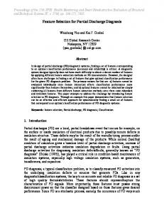
An electrical discharge can cause the material in its immediate vicinity to vaporize. Such an explosion of mechanical energy creates a spherical pressure wave disturbance emanating from the discharge source. In the case of discharge in oil-filled transformers, the spherical pressure wave is of a longitudinal nature when propagating in the oil. Upon arriving at the transformer tank, it then excites a longitudinal wave and a shear wave propagating along the tank wall. Analogous to the approach used in ray optics, this can be treated as equivalent to straight-line ‘pressure beams’ originating from the discharge site and propagating equally in all
directions, each arriving at the tank wall with a different incident angle θ. Consider a pressure sensor that is attached externally to the tank wall and at an angle ψ from the normal as shown in Figure 1. Apart from the direct path (straight line between the PD source and the sensor), there are other indirect paths that the pressure beam can travel before reaching the sensor. The propagation velocity in oil (~1400 m/s) is significantly lower that that in the steel tank (~5900 m/s longitudinal and ~3200 m/s shear). Consequently, the direct path – although the shortest - is not necessarily the quickest path for the PD-induced pressure disturbance to reach to sensor. Discharge source
ψ Y θ Tank wall x
Sensor X
Figure 1: Model for pressure wave propagation.
It can be shown that the propagation time is [1, 2]: tp = =
Y X − Y tan α + voil .cos α vsteel X 2 +Y2 voil
if ψ > α
(1a)
if ψ ≤ α
(1b)
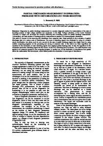
where v oil and v steel are the longitudinal propagation velocities in oil and steel respectively and α is the critical incidence angle: v α = sin −1 oil (2) v steel The propagation time can be measured by recording simultaneously the electrical and acoustic signals (Figure 2). This would enable the determination of the distance between the PD source and the sensor and thus the location of the PD source. However, the problem is the ambiguity as indicated by Eq.1. This is a major drawback of using externally-mounted pressure sensors. Another disadvantage is a significant reduction of signal sensitivity.
The relationship between the electrical discharge magnitude and the associated acoustic pressure is complicated [3]. In both gases and liquids, it was found that the pressure level can vary considerably even for a fixed electrical discharge value. A variation of ten-toone is not uncommon and this is due to inconsistency in the discharge-induced formation of gas. Measurements of the acoustic pressure levels in the frequency range of 100-300 kHz from discharges ranging from 10pC to 10nC in mineral oil showed that the pressure level is, on the average, approximately proportional to the square root of the electrical discharge. However, for larger discharges the pressure level appears to be directly proportional to the electrical discharge magnitude. The acceptable discharge level varies with different plant items. For the case of oil-filled transformers in particular, it is in the order of a few tens of pCs. The pressure picked up by the sensor is inversely proportional to the square of the distance from the sensor to the PD source. The acoustic pressure at 10cm for a 1pC discharge source is about 0.2 Pa and from a 10pC discharge source is 0.6 Pa [3]. As a rule of thumb, the dangerous discharge threshold in transformers is ~100pC which corresponds to 2 Pa. Thus chosen in this paper as a design criterion, it is desirable to have a sensor with a minimum detection sensitivity of 2 Pa. The sensitivity of typical piezoelectric (PZT) sensors such as the Physical Acoustics R15I-AST which has a built-in preamplifier is about -30dB (reference to 1V/microbar). In other words, 0.1 Pa would result in a 31.6mV output signal. This level can be easily recognised as the resolution of a typical oscilloscope is 1mV. However, the sensor must be mounted externally and thus the pressure received is significantly attenuated so the actual discharge level required is much higher. The frequency band of typical PZT sensors used for oilfilled transformer application is in the range 100 kHz500 kHz with a peak response at around 150 kHz. Some broadband sensors can go up to 1MHz. PZT pressure sensors have been used in practice, particularly for detecting and locating PDs in oil-filled power transformers [3, 4]. However, the traditional use of PZT sensors clamped onto the outside of the transformer tank wall results in low sensitivity due to acoustic impedance mismatch and attenuation. The sensitivity can be improved by using composite (piezoelectric ceramic in epoxy) transducers immersed in the oil inside the transformer [5]. However, as with PZT sensors, they must be hard wired to recorders and there is thus some safety constraint on their positioning within the high electric field environment within the transformer tank. To prevent such location constraints, a sensor with no electrical connection and with very high insulation strength is needed. A solution to this problem is the use of optically interrogated pressure sensor systems.
3. Figure 2: Measuring the propagation time
OPTICAL SYSTEMS
Optically interrogated pressure sensing systems utilize the optical fibre as the transmission medium for the light
signal. As for the sensor itself, it can also be made from part of the same optical fibre. Such an intrinsic optical fibre sensor (OFS) system enables better sensitive and accurate measurement for a wide range of physical parameters, including pressure measurements. Being electrically non-conducting and explosion-proof, the OFS are well suited for use in hostile environments such as those encountered inside HV power equipment where electronics cannot operate. Furthermore, they are immune to EMI and their use inside power equipment does not compromise the integrity of the equipment insulation system. Thus, optical fibre sensors can, for example, be put within the high voltage structure of transformer windings to provide very close access to those insulation sites where potential faults may develop. This close proximity will give increased sensitivity and better location of such PD sites. Hard-wired piezoelectric sensors are not able to be placed in such hostile environments. It should also be noted that fibre sensors have also been used to measure temperature [6], which is also a difficult quantity to measure inside transformer windings where the highest temperatures occur. Historically, the use of OFS for detecting PD-induced pressure waves in oil-filled HV power transformers was first introduced by the authors [7]. The detection method is based on the principle that the acoustic pressure wave impinging on the fibre sensing element induces mechanical stress in the fibre core. The effect is to change both the fibre length and its refractive index. Consequently, the phase of a light beam traversing the fibre will be affected as well. In other words, the light wave is phase-modulated by the acoustic pressure wave and this can be extracted with a suitable demodulator and a record of the partial discharge thus obtained. Although the possibility of the OFS for such PD detection was proven in [7] and in further investigations afterwards [8, 9] and related applications by other researchers [10, 11], the technique requires further research on the sensor configuration to improve the sensitivity and to reduce the physical size of the sensing element. The sensing element in the system developed by the authors requires a long length of fibre (~150 m). Although this can be wound into a doughnut coil, the size is still considerable (~50 mm in diameter). This makes it impractical for installing the sensor in confined spaces such as inside a transformer winding. Another limitation is that it requires a highly stable laser light source with good coherence over a long length. Fringe fading is also a problem that is caused by random polarisation rotation. Furthermore, the sensor was not able to respond to the pressure waves in the higher frequency range. Thus it is not possible to carry out any detailed investigation of the fundamental correlation of pressure waves in a PD with its corresponding electrical current characteristics Recently, it was demonstrated that a similar intrinsic OFS system using a fibre sensing coil of 14mm diameter was able to achieve a sensitivity of 1 Pa [12]. Although this is a significant improvement, the size of the sensing element still poses a problem for practical application.
To overcome this, there are two possibilities. One is the use of Fibre Bragg Gratings (FBG) as an intrinsic sensing element and the other is the use of Fabry-Perot interferometer as an extrinsic sensing element. The latter method has been applied to PD-induced pressure detection [13]. The sensing element, known as the Fabry-Perot cavity, is formed by two parallel reflecting surfaces – a diaphragm and the end face of an optical fibre. It is very compact in size. The diaphragm has a radius of 1.25 mm and 3.5 nm/kPa deflection. The sensitivity of the system is 10 Pa. 3.1.
FBG AND DFBFL SENSING SYSTEMS
Fibre Bragg Gratings (FBG) can be utilised as an intrinsic sensing element. This structure is a very short length of optical fibre with a periodically varying refractive index core, formed by exposure of the core to an intense optical interference pattern [14]. FBG inherits all the favourable characteristics of an optical fibre sensor. Furthermore, its use can solve a number of practical problems. Its length can be as short as a few millimetres compared to more than a hundred metres for the sensing element of other intrinsic OFS. Thus, a point sensor can be realized using the FBG. Its small size makes it possible for insertion into confined areas, e.g. inside the windings of high-voltage transformers. Because of the FBG short length, the requirement of a laser source with long coherence span is not necessary. Thus a semiconductor laser can be used instead of a gas laser. It should be noted that FBG has been used in HV transformers but only to monitor the temperature [15]. The work done here by the authors is the first investigation on the viability of FBG as a PD-induced pressure sensor. Transmitted signal
Broadband Optical Source
coupler
Wavelength monitoring
Grating sensor
Wavelength monitoring
Reflected signal
Figure 3: Basic FBG sensing system [3].
Another important aspect of the FBG innovation is that sensors can be readily wavelength-division multiplexed. This allows multi-point sensing and also simultaneous measurement of various parameters [16]. Therefore fibres with distributed sensor arrays can be embedded into the structure (e.g. transformer windings) to allow multiple measurements of pressure and temperature. Distributed sensing enables more accurate location of the problem area. The spectral characteristics of the acoustic pressure wave can reveal nature of the discharge type [17]. Thus broadband detection would be advantageous. It has been shown that an optical fibre hydrophone with fibre Bragg grating has the potential to operate in a wide range of frequency [18]. The ability to respond, say up to 1MHz,
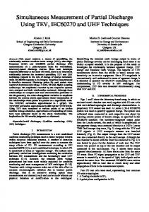
A basic FBG sensing system is shown in Figure 3. The basic principle of operation is to monitor the shift in wavelength of the reflected Bragg signal with changes in the measurand such as pressure. The Bragg wavelength is λB = 2nΛ where Λ is the grating pitch and n is the effective index of the core. When injecting a broadband optical source into the fibre, a narrowband spectral component at the Bragg wavelength is reflected by the grating and thus will be missing in the transmitted signal. Perturbation of the grating will cause a shift in the Bragg wavelength and this can be detected by monitoring either the reflected or the transmitted signal. If FBG is to be used for detecting pressure in oil-filled transformers, the grating length should not be longer than the acoustic signal wavelength to prevent amplitude modulation between the reflected Bragg signal and the PD signal. If 300 kHz is chosen as the upper limit of the acoustic signal frequency and knowing the propagation velocity in oil (~1400 m/s), the grating length should not exceed 5 mm. Reflectivity of Uniform Bragg Grating 1 induced index change =4*10e-4
0.9
Reflectivity
induced index change =2*10e-4
Once the sensitivity of the FBG is determined, the minimum detectable pressure when using a photodetector can be calculated. The minimum detectable pressure of a photo-detector is: Pmin
induced index change =3*10e-4
2hfB = I 0η
0.5
∆φ ∆P
−1
(4)
where h is the Planck’s constant, f is the frequency of light wave, B is the detector bandwidth, Io is the photodetector current, η is the quantum efficiency. For a detector bandwidth of 1 MHz, Bragg wavelength of 1558 nm and a laser source of 25 mW, the theoretically calculated minimum detectable pressure is ~97 Pa. Such sensitivity is not quite satisfactory and further investigation is required to optimise the design configuration and parameters. -10
FBG2
DBFFL
-15
FBG1 -20 -25 -30 1524
0.8 0.7
least 2x10⁻⁴ is required for this particular configuration as the reflected power loss would be less than 10%.
Return power (dB)
will assist in bringing out subtle characteristics of the PDs which will allow some better assessment of condition and ageing.
1525
1526
1527
1528
1529
1530
1531
1532
Wavelength (nm)
0.6 0.5
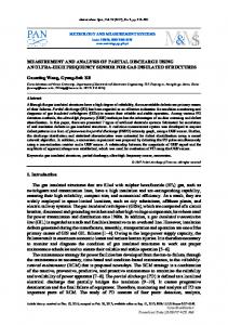
Figure 5: Reflected Bragg wavelength spectra
0.4 0.3 0.2
induced index change =1*10e-4
0.1 0 1.556 1.5565 1.557 1.5575 1.558 1.5585 1.559 1.5595 1.56 1.5605 1.561 -6 Wavelength(m) x 10
Figure 4: Bandwidth analysis of a uniform Bragg grating.
The effectiveness of an interferometric detection system using FBG can be determined from the relationship between the induced pressure change (∆P) and the change in phase (∆φ). It can be shown that: ∆φ −2π nd 0.78 ( 2v − 1) = E ∆P λB
The use of FBG as the sensing element can be extended in the form of distributed-feedback fibre laser (DFBFL). This configuration consists of a pair of wavelength matched fibre Bragg gratings written in a short section of Erbium doped fibre. The arrangement is essentially an intrinsic Fabry Perot structure that functions as a single mode laser with extremely narrow line-widths. Preliminary results from a recent study showed that a DFBFL with 10cm cavity length, made with modern fibre and grating writing techniques can act as a very compact sensing element, whose lasing wavelength is highly sensitive to pressure disturbance [19].
(3)
where λB is the Bragg wavelength, v is the Poisson’s ratio, E is the Young’s modulus, and nd is the optical path difference (OPD). Note that the sensitivity can be increased by increasing the OPD. Thus the aim is to maximise the OPD but the constraint is that the OPD must be shorter than the reflected coherent length. In this case, it must not exceed the grating length of 5 mm. A bandwidth analysis was carried out by computer simulation using MatLab. The results are shown in Figure 4 for uniform Bragg grating with grating length of 4.5 mm and induced index change ranging from 10-4 to 4x10⁻⁴. It can be seen that induced index change of at
Figure 6: Responses from FBG and PZT sensors.
Preliminary experimental work was carried out on two FBG sensors (denoted as FBG1 and FBG2) and a DFBFL sensor. These are made from step index fibre
with uniform grating and a grating length of 4cm. The FBG sensors were coated with epoxy and the DFBFL was coated with silicone. The reflected spectra obtained when these sensors were immersed in oil are shown in Figure 5. Figure 6 show the response of FBG1 sensor (top trace) as compared to those of the PZT sensor (two bottom traces). Work on the electronics (amplifier and filter) is still in progress to improve the SNR of the detection system.
cavity can become a source of discharges itself. One solution is filling the cavity with, instead of air, another gas of higher dielectric strength such as sulfur hexafluoride SF6 (a common type of gaseous insulation used in HV power equipment). This of course would affect the sensitivity and frequency response of the sensor.
3.2.
Apart from application in power transformers, the authors have used the OFS developed in an SF6 Gas Insulated System configuration where it is wrapped around the outside casing [9]. It is also possible to extend the use of the OFS system by wrapping it around HV porcelain and composite material bushings. In large items of HV equipment such as power transformers, instrument transformers and some switchgear, the insulation in the bushing is the source of a majority of insulation problems. The traditional piezoelectric sensors for PDs are very insensitive to faults there because they have to be placed on the metal tank of the equipment so as not to cause problems with the insulation. Thus they are a long distance from the fault site and result in poor sensitivity. On the other hand, the optically interrogated sensor system does not affect the dielectric strength of the bushing and thus it has much higher sensitivity and is able to monitor bushing faults. This gives the OFS system an enormous advantage over PZT sensors when looking at bushing faults. The use of the new sensor in such an important application is being explored by the authors in the laboratory using a bushing model. Although this work is still in its embryonic stage, it is the first time that such a technique has been used. This technique lends itself to permanent installation for online monitoring as with the transformer.
MEMS PRESSURE SENSOR
Another significant recent development is the use of micro-electromechanical systems (MEMS) sensors for pressure sensing. Over the past few years, the MEMS technology is emerging as an intensive area of research and development. Based on micro-electronics fabrication technology, the micro-mechanical components can be fabricated from a silicon substrate by using compatible micro-machining processes to selectively etch away parts of the silicon wafer or add new structural layers. Such micro-mechanical components can be readily integrated with other micro-electronic components to form a MEMS device. Optically interrogated pressure sensors using MEMS have been successfully demonstrated [20]. Here, an optical fibre based system is still employed but the pressure sensing element is a high-precision microcavity with a flexible silicon diaphragm. The MEMS sensor structure can be aligned and fixed to the end of an optical fibre for optical interrogation. The silicon diaphragm and the cavity act as the optical reflector forming a Fabry-Pérot interferometer. Changes in the pressure will cause the diaphragm to move and thus modulates the gap length in the cavity. For a square diaphragm of thickness h and half side length a, the centre deflection d can be expressed as a function of the pressure difference P (in pascal) as: d=
Pa 4 (1 − v 2 ) 4.2 Eh3
(5)
where E is the Young’s modulus and v is the Poisson’s ratio of the diaphragm material. As an example, for a 4x4 mm silicon diaphragm with a thickness of 5µm, the deflection would be 0.4µm in response to a pressure difference of 2 pascals. A fabrication technique has been developed to fabricate the entire MEMS structure directly on an optical fibre end face [20], thus improving the reliability and robustness of the sensor system. The process comprises photo-lithographic patterning, wet etching of a cavity, and anodic bonding of a silicon diaphragm. Recently, an ultra-sensitive optical MEMS sensor for PD acoustic detection was developed [21]. It was claimed that the sensor has a resolution of 2.8 Pa and a resonant frequency of ~90 kHz. Such a pressure sensor could prove suitable but further work is still required. One potential problem is that although no conductive materials (which will compromise the insulation of the power equipment being monitored) are used in the MEMS structure, the micro-
3.3.
APPLICATIONS IN HV EQUIPMENT
Joints in cables are also a major cause of concern in terms of partial discharge activity and a fibre sensor wrapped around the joint would also be able to detect PDs in the cable joint. As with the transformer and bushings, a permanently installed fibre wrap sensor would provide an inexpensive and easy means of on-line monitoring of cable accessory insulation.
4.
CONCLUSIONS
Detecting PD-induced acoustic pressure using optically interrogated sensing systems offers a number of significant advantages. Such sensors are electrically nonconducting, immune to EMI, chemically inert, small in size, suitable for distributed sensing, and capable of recording multiple parameters simultaneously. They have the potential for practical use in monitoring a wide range of high-voltage power system equipment.
REFERENCES [1]
B.T. Phung, R.E. James, T.R. Blackburn and Q. Su, "PD ultrasonic wave propagation in steel transformer tanks", Paper 74.04, 7th Int. Symp. On HV Engineering, Dresden, Germany, Aug. 1991, pp.131-134.
[2]
B.T. Phung, T.R. Blackburn and Z. Liu, “Acoustic Measurements of Partial Discharge Signals”, Journal of Electrical and Electronics Engineering, Australia, Vol.21, No.1, 2001, pp.41-47.
[14]
A.D. Kersey et al, “Fiber grating sensors”, IEEE Journal of Lightwave Technology, Vol.15, No.8, Aug.1997, pp.1442-1463.
[15]
Teunissen, J.; Merte, R.; Helmig, C.; Peier, D., “Fiber Optical Online Monitoring for Highvoltage Transformers ", Fiber Optic Sensor Technology II, SPIE-Proceedings Volume 4204, Boston 2000, pp198-205U.
[3]
R. Bartnikas and E.J. McMahon (Ed.), Engineering Dielectrics, Vol.1, ASTM Publications, Philadelphia, 327-408, 1979.
[4]
E. Howells and E.T. Norton, “Detection of partial discharges in transformers using acoustic emission techniques”, IEEE Trans., Vol. PAS97, No.5, 1978, pp.1538-1549.
[16]
Hathaway, M.W. et al, “Combined ultrasound and temperature sensor using a fibre Bragg grating”, Optics Communications, Dec.1999, pp.225-231.
[5]
J. Unsworth et al, “On-Line, Early Warning, Remote Partial Discharge Monitor for High Voltage Power Transformers,” Proc. 15th Int. Conf. on Electricity Distribution,” 1/ p.10 CIRED, June, NICE 99.
[17]
Boczar, T., “Identification of a specific type of PD from acoustic emission frequency spectra”, IEEE-DEI Trans., Vol.8, No.4 , Aug.2001, pp. 598-606.
[18]
[6]
G. Betta, A. Pietrosanto and A. Scaglione, “An enhanced fiber optic temperature sensor system for power transformer monitoring”, 17th IEEE Instrumentation & Measurement Technology Conf., 2000, pp.153-158.
Takahashi, N. et al, “Development of an optical fiber hydrophone with fibre Bragg grating”, Ultrasonics 38, 2000, pp.581-585.
[19]
I. Leung, Z. Brodzeli, T. Whitbread, X. B. Chen, G. D. Peng, “A distributed-feedback fibre laser based optical fibre hydrophone system with very high-sensitivity”, Photonics Asia 2004, Advanced Sensor Systems and Applications II., Beijing, China, November 2004.
[20]
D.C. Abeysinghe et al, “A novel MEMS pressure sensor fabricated on an optical fiber”, IEEE Photonics Technology Letters, Vol.13, No.9, Sept.2001, pp.993-995.
[21]
X. Wang et al, “An ultra-sensitive optical MEMS sensor for partial discharge detection”, Journal of Micro-mechanics and Microengineering , 15, pp.521-527, 2005.
[7]
[8]
T.R. Blackburn, B.T. Phung and R.E. James, “Optical fibre sensor for partial discharge detection and location in high-voltage power transformers”, 6th Int. Conf. on Dielectric Materials, Measurements & Appl. (DMMA), Manchester, UK, Sept.1992, pp.33-36. T.R. Blackburn, B.T. Phung, D. Krcho. and A. Zargari, "Modified optical fibre sensor for partial discharge detection in high-voltage power transformers", Proc. Australasia Universities Power Engineering Conf., Adelaide, Sep.27-29, 1994, Vol.2, pp.417-422.
[9]
A. Zargari and T.R. Blackburn, “A noninvasive optical fibre sensor for detection of partial discharges in SF6 GIS systems”, Proc. Int. Symp. On Elect. Insulating Materials, Himeji, Japan, Nov.2001, pp.359-362.
[10]
J.A. Cosgrave et al, “Acoustic monitoring of partial discharges in gas insulated substations using optical sensors”, IEE Proc., Part A: Science, Measurement and Technology, Vol.140, No.5, Sept.1993, pp.369-374.
[11]
G.R. Jones et al, “Optical fibre sensing as a basis for the intelligent monitoring of power switchgear”, IEE 5th Int. Conf. on Trends in Distribution Switchgear, 1998, pp.181-186.
[12]
M. MacAlpine, Z. Zhiqiang, M. S. Demokan, “Development of a fiber-optic sensor for partial discharges in oil-filled power transformers”, Electric Power Systems Research, Vol.63, Issue 1, pp. 27-36, Aug 2002.
[13]
B. Yu, D. W. Kim, J. Deng, H. Xiao, and A. Wang, “Fiber Fabry-Perot sensors for detection of partial discharges in power transformers”, Applied Optics-OT, Vol. 42 Issue 16, pp. 32413250, June 2003.