Distributed Estimation of Linear Acceleration for Improved Accuracy in Wireless Inertial Motion Capture A. D. Young
[email protected]
M. J. Ling
[email protected]
D. K. Arvind
[email protected]
Institute for Computing Systems Architecture School of Informatics, University of Edinburgh 10 Crichton Street, Edinburgh EH8 9AB, United Kingdom
ABSTRACT Motion capture using wireless inertial measurement units (IMUs) has many advantages over other techniques. Achieving accurate tracking with IMUs presents a processing challenge, especially for real time tracking. Centralised approaches are bandwidth-intensive and prone to error from packet loss. Methods based solely on local knowledge have poor dynamic accuracy, due to ambiguities introduced by linear acceleration. First we analyse the effect of linear acceleration on orientation accuracy. We then present an efficient distributed method which uses a model of the subject’s body structure to estimate and correct for linear acceleration. We validate the behaviour of this method on data from combined optical/inertial capture experiments, and show improved gravity vector estimation and a corresponding increase in orientation accuracy. We estimate the runtime, memory, communication and power requirements of our method, and show that it is a practical software modification to an existing system. The proposed solution is the first to use collaboration between wireless IMUs to improve accuracy.
Categories and Subject Descriptors C.3 [Special-Purpose and Application-Based Systems]: Real-time and embedded systems
General Terms Theory, Algorithms, Experimentation
Keywords Wireless sensor network, inertial motion capture, in-network processing, distributed computing, real-time, body sensor network.
1.
INTRODUCTION
Wireless inertial measurement units (IMUs) can be used to perform motion capture of humans and animals, offering
Permission to make digital or hard copies of all or part of this work for personal or classroom use is granted without fee provided that copies are not made or distributed for profit or commercial advantage and that copies bear this notice and the full citation on the first page. To copy otherwise, to republish, to post on servers or to redistribute to lists, requires prior specific permission and/or a fee. IPSN’10, April 12–16, 2010, Stockholm, Sweden. Copyright 2010 ACM 978-1-60558-955-8/10/04 ...$10.00.
ease of use and the ability to operate in scenarios where alternative capture solutions are infeasible. Optical and magnetic techniques require external infrastructure that constrains the available tracking volume, whilst mechanical methods limit freedom of movement [1]. IMU based capture can offer effectively unlimited tracking volume, with data either captured and stored on the body or transferred to WLAN or cellular networks. Inertial capture operates primarily by determining the orientation rather than position of each IMU [2,3]. The subject wears multiple IMUs, each attached to a body segment to be tracked, the deployment following the major bones of the skeleton. With knowledge of the orientations of each body segment over time, along with the structure of the body, the overall posture of the subject can be tracked. An IMU typically comprises three sets of tri-axial sensors: accelerometers, magnetometers, and rate gyroscopes. To estimate the orientation of the IMU, the rate gyroscope data is integrated and the resulting relative orientation estimate fused with an absolute estimate, based on observing the directions of the local gravitational and Earth magnetic field vectors. Approaches to this data fusion vary from simple complementary filters [4] to more complex extended Kalman filters that attempt to model kinematics of the IMU and associated body segment [5]. All commercial inertial motion capture systems, and the majority of research systems to date, transmit raw sensor data to a PC for processing. This centralised approach eases the use of more complex processing, but is prone to error from packet losses [6], and its bandwidth requirements limit the number of IMUs that can be supported on a channel in fully-wireless solutions. In previous work we presented the Orient system, in which each IMU instead performs its own orientation estimates locally, reducing bandwidth requirements by 79% over central processing and thereby enabling real-time, fully-wireless, full-body capture at 64Hz for the first time [3]. This system is capable of tracking motion with latencies on the order of tens of milliseconds, as required for interactive applications such as virtual environments [7–9]. Unfortunately, any orientation estimate based purely on local knowledge is limited in its accuracy by the effects of gyro drift and linear acceleration. Drift arises in a gyroscopebased orientation estimate from a combination of sensor noise, bias, and numerical integration error. The direction of gravity, estimated from accelerometer data, must be used to correct for this drift. Yet the estimation of the gravity vector is hampered by the superposition of linear accelerations resulting from the subject’s movements. With no further
knowledge of the nature of these movements, a single IMU cannot unambiguously track its orientation. Hence, in this paper we present a distributed method for estimating the linear accelerations experienced by each IMU in a full-body real-time inertial capture system. By subtracting these accelerations from measured accelerometer readings before use, the orientation error due to linear acceleration can be substantially reduced. The analysis presented in this paper is fundamental to understanding the sources of inaccuracies in the estimation of the orientation of body segments for wireless inertial motion capture. The method for compensating for the inaccuracies is tractable on the Orient IMU platform, which enables more accurate real time motion capture than previously possible. This is an essential contribution towards obtaining accurate results using inexpensive wireless IMUs, which is necessary for their widespread adoption in analysing the biomechanics of human movements. The potentially low costs of IMU based capture, freedom from limited tracking volumes, and the availability of real-time output, all contribute to enabling new applications in areas where motion capture has not previously been accessible. The remainder of this paper is organised as follows. Section 2 places the work in the context of existing research. Section 3 establishes the problem to be solved, by outlining the theory of vector observation, investigating the contribution of linear accelerations to error, and analysing the effects of existing error reduction techniques. In Section 4, we derive a method for estimating the linear accelerations of an IMU, based on a subset of global knowledge about the structure and movements of the body. From this we develop our proposed solution. Section 5 presents a methodology for combined experiments with optical motion capture, and a preliminary experiment to verify the behaviour of the proposed linear acceleration estimation algorithm. In Section 6 we examine the runtime, memory, communication and power costs of our method. Finally, Section 7 summarises our conclusions.
2.
RELATED WORKS
A number of wireless IMUs and supporting algorithms have been developed within the sensor network community [3, 10–12], in biomedicine [13, 14], and for virtual reality [2, 5, 15, 16]. However, only one previous work attempts to directly address the issue of linear acceleration [14]. Existing research has approached the problem of orientation estimation of multiple limb segments by treating each limb segment individually. Variants of Kalman filters are usually employed to fuse data from an individual device’s sensors. Use of the Kalman filter requires assumptions to be made about the dynamics of the motion being captured. The requirement of providing a dynamics model limits the generality of the proposed orientation estimation algorithms. The human body is capable of a large variety of motions with varying dynamics, and choosing a process model is, therefore, extremely difficult. Furthermore, inertial motion capture is not inherently limited to human subjects. Treating limb segments individually discards important information available from the knowledge of limb connectivity. The motion of limb segments is directly linked to the connectivity of the limbs. No existing work within the sensor network community has addressed this important constraint.
l −g θ −a
a
g
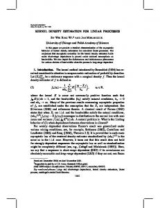
Figure 1: Measurement of IMU acceleration
3.
EFFECT OF LINEAR ACCELERATIONS
The orientation of a static IMU can be estimated based on observations of the local gravitational and magnetic field vectors. The vector observation process involves calculating the rotation matrix, R, such that: bi = Rwi
∀i ∈ (1, . . . , n),
(1)
where bi , . . . , bn are the observed vectors in the IMU’s local co-ordinate frame, and w1 , . . . , wn are the reference vectors in a shared global co-ordinate frame. In the standard righthanded aerospace co-ordinate frame, the direction of gravity defines the z-axis; the direction of the Earth’s magnetic field vector, projected onto the horizontal plane, defines the x-axis, and the y-axis points eastwards. In general, with vector observations corrupted by noise, no exact solution for R exists. A variety of estimation methods exist, with different advantages [4]. We will now consider the case of a non-static IMU. The measurement equation for the accelerometers, ignoring noise, is: a = −g + l
(2)
where g is the constant downward acceleration due to gravity, and l is the linear acceleration of the device in units of the magnitude of g. The acceleration due to gravity points in the opposite direction to the normal to the Earth’s surface, as illustrated in Figure 1. Therefore, the measured acceleration is inverted to produce an estimate of the local down vector. Any component of linear acceleration not parallel to the gravitational field will result in an error in estimating the Earth normal. We now derive the worst case error angle due to linear acceleration, working in two dimensions for clarity. The results extend easily to the three-dimensional case. Figure 2 illustrates the geometry giving rise to the worst case error for a linear acceleration of given magnitude. The circle C1 represents the possible values of −a, given a linear acceleration of magnitude l = k−lk. The worst case error angle, θmax , occurs when −a lies on the tangent from the origin O to C1 . θmax = tan−1
„ « x . y
(3)
The point of intersection of C1 and −a is the intersection of the two circles C1 and C2 , given by Equations (4a) and (4b) respectively. x2 + (y − 1)2 − l2 = 0 „ «2 „ «2 1 1 x2 + y − − =0 2 2
(4a) (4b)
O
Algorithm 1: Vector observation Input: a the measured acceleration vector, m the measured magnetic field vector Output: qvo the estimated orientation in quaternion format begin a e3 = ; kak m − e3 (e3 · m) e1 = ; kmt − e3 (e3 · mt )k e 2 = e3 × e1 ; ˆ = [e1 : e2 : e3 ]T ; R qvo = MatrixToQuaternion(R); end
C2 y
−a
θ g x −l
C1
Figure 2: Geometry for calculating worst-case linear acceleration error timates are fused using the filter state update equations:
y = 1 − l2 .
(5)
By Pythagoras: x=
∴ θmax
q
l2 − (1 − y)2 =
p l2 − l4
« „√ 2 8 l − l4 > >tan−1 , > 2 > < „ 1 − l „√ 2 «« l − l4 π = −1 liml→1 tan = , > > 2 > 1 − l 2 > : π,
(6)
0≤l1
(7) The worst case error in the observed direction of gravity is therefore bounded as shown for linear accelerations less than 1g in magnitude, reaches ±90◦ in the limit as the magnitude approaches 1g, and is ±180◦ for all magnitudes of more than 1g, hence effectively unbounded in orientation space. The effect of this gravity observation error on the overall vector observation result will depend on the vector observation algorithm chosen. The method used for the results in this paper, developed in previous work [3], uses GramSchmidt ortho-normalisation and is defined in Algorithm 1. It should be noted that this method is formally sub-optimal, in that it discards the vertical component of the magnetic field measurement. Optimal estimation techniques, such as the QUEST [17] algorithm, incorporate this extra information, thereby reducing their sensitivity to linear acceleration but at the cost of an increased sensitivity to magnetic field distortions. With only magnetic and acceleration input vectors, there is insufficient redundancy to discount either vector, and hence any vector observation algorithm must suffer some error due to linear accelerations. Therefore, a means for eliminating linear accelerations from the input data is complementary to any vector observation technique, although the exact sensitivity to error will vary with the algorithm chosen.
3.1
1 ω qˆt−1 , ω = (0, ω) (8a) 2 qˆI = qˆt−1 + q∆t ˙ (8b) 1 qvo − qˆI ) , (8c) qˆt = qˆI + (ˆ k where ω is the rotational rate, in rad/s; ∆t is the time step between filter updates; qˆt is the estimated orientation quaternion at time t seconds; k is a filter co-efficient, k ≥ 1; qˆI is the inertial estimate of orientation; and, qˆvo is the estimate of orientation from vector observation. The filter co-efficient, k, controls the rate at which the orientation estimate is corrected towards the vector observation estimate. Low values of k result in faster convergence between the estimated orientation and vector observation. Therefore, under the influence of linear acceleration, low values of k allow the estimated orientation to rapidly diverge from the true orientation. Larger values result in smaller correction steps, reducing the error introduced by transitory accelerations, but increasing convergence time when the device is not experiencing linear accelerations. Increasing k too far results in the filter becoming unstable, as it can no longer correct for drift introduced by rate gyroscope bias and integration errors. From Equation (8c) it should be clear that, for any finite value of k, linear accelerations will result in corruption of the estimated orientation. This result remains true even with a time varying k, such as in Kalman filter implementations. q˙ =
Combining (4a) and (4b), and solving for y:
Orientation Data Fusion
The orientation estimate generated by vector observation, converted to quaternion form, is fused with an inertial estimate based on the integration of rotational rate data from rate gyroscopes. In our implementation the orientation es-
3.2
Detecting Linear Acceleration
Equation (2) indicates that the measured acceleration of a device is the sum of the constant acceleration due to gravity and linear acceleration due to movement. The effects of linear acceleration can be reduced if the presence of linear acceleration can be detected, and corrupted vector observations discarded. A simple approach to detecting linear accelerations is based on the magnitude of the measured acceleration vector. From elementary vector mathematics we know that if this magnitude differs from 1g then it must include a linear acceleration component. However, if the magnitude is equal to 1g then this does not imply that we are correctly observing gravity. There are many solutions to: kak = kl − gk = 1, other than the trivial solution l = 0.
(9)
Algorithm 2: Gated filter
θmax (deg)
begin Initialise a0 , m0 , ω 0 = GetNextSample(); qˆ0 = VectorObs(a0 , m0 ); end while running do at , mt , ω t = GetNextSample(); begin Inertial orientation update 1 q˙ = ω qˆt−1 ; 2 qˆt = qˆt−1 + q∆t; ˙ end begin Gated drift correction if 1 − aT < kak < 1 + aT then qvo = VectorObs(a, m); 1 qˆ = qˆ (qvo − qˆt−1 ); k end end qˆ = qˆ/kˆ q k; Output(ˆ qt ); end
(1 − aT )2 − l2 + 1 2 q 2 x = l − (1 − y)2 „ « x θmax = tan−1 . y
1.5
2.0
Maximum gate threshold
−g
(11)
(12)
(13a) (13b) (13c)
The effect of gating on the maximum error angle as a function of acceleration is shown in Figure 3. By applying a gating threshold, the maximum error is reduced for linear accelerations with magnitude less than 2g. The possible errors are still substantial. While gating still allows for substantial potential errors, the probability of error is decreased since drift correction is suppressed for acceleration that lie outside the gate. The reduction of error probability is illustrated in Figure 4 for
Minimum gate threshold Linear accelerations of magnitude l accepted by gate Possible linear accelerations of magnitude l
(10)
the minimum acceleration gate threshold. The resulting error can then be calculated as: y=
1.0
Possible accelerations �a� = 1g
which represents the locus of possible 1g accelerations, the maximum error is the same as without gating. If this condition is not satisfied, then the maximum error occurs at the intersections of (4a) and: x2 + y 2 = 1 − aT ,
0.5
Figure 3: Effect of gating threshold aT on θmax .
where aT is the gating threshold. Accelerometer gating affects the maximum error angle due to linear acceleration. In the case where the point (x, y) calculated from Equations (6) and (5) lies within aT of the circle: x2 + y 2 = 1,
no gate aT = 0.1 aT = 0
l(g)
In practice, with noise present in the accelerometer measurements, we would wish to use some bounded region around 1g for the gating process [18]. In the gated filter given in Algorithm 2, as implemented in the Orient system, drift correction based on vector observation is only performed if: 1 − aT < kak < 1 + aT ,
180 160 140 120 100 80 60 40 20 0 0.0
Figure 4: Visualising the effect of gating on potential error a linear acceleration of magnitude l, which is equally likely in any direction. The smaller sphere represents the possible measured accelerations, while the shaded zone represents accelerations that are accepted by the gate. In this case the probability of error is the ratio of the area of the shaded zone to the surface area of the sphere. In practice the distribution of linear accelerations is highly unlikely to be uniform. Therefore the error which is likely to be experienced is highly dependent on the motion of the IMU. Some motions may never cause errors, while other motions may always result in the maximum error.
3.3
Summary of Problem
Drift correction through vector observation is necessary in IMUs to mitigate the effects of rate gyroscope bias and integration errors. Without drift correction the uncertainty of the inertial estimate would grow continuously, quickly becoming worthless. The presence of any linear acceleration component in the measured device acceleration can lead to error in the orientation estimated by a vector observation algorithm. The resulting errors are substantial, reaching a maximum error of ±180◦ for linear accelerations greater than 1g. The use of a filter blending co-efficient helps to reduce the rate of error growth due to inaccurate vector observations but cannot prevent errors from occurring. Detection of linear acceleration, based on the magnitude of the measured
Jk
ω
osk oJk+1
Sk Jk+1
lr o
osk+1 oJk+2
J
J
Sk+1
α p o
h
r
lt p (b) Tangential Acceleration
(a) Radial Acceleration Jk+2
Figure 6: Relationships of linear acceleration to angular parameters Figure 5: Example body model showing detail of joint and sensor positions acceleration, can reduce the probability of inaccurate observations and the magnitude of the resulting error. However, this simple gating condition is inadequate to detect all possible linear accelerations. Furthermore, prolonged movements can result in long periods in which the acceleration remains outside the accepted range, during which drift correction cannot be performed and gyroscope integration errors accumulate.
4.
ESTIMATING LINEAR ACCELERATION
In Section 3 we concluded that linear acceleration is a primary source of dynamic error in inertial motion capture, and that simple gating is not sufficient to remove the errors. We have therefore investigated the possibility of estimating linear acceleration based on the knowledge of the subject’s body model. We will use the model shown in Figure 5 to examine the problem of estimating the linear acceleration of a sensor. The model consists of joints, Ji , and sensors, Si . Each joint is a perfect spherical joint; in other words, it can rotate in any direction about a single point. Furthermore, each joint has a local co-ordinate frame attached to it; the rotation of the joint therefore being the rotation of the local co-ordinate frame. Sensors are assumed to exist at a fixed point in a joint’s co-ordinate frame, their position given by a constant offset vector, oSi , from the joint centre. Joints form a tree structure with the position of a child joint given by an offset, oJi , from the parent joint centre. We consider first the case of a single joint, fixed in space, rotating at an angular velocity of ω rad/s, and with angular acceleration of α rad/s2 . Under these circumstances, a point, p, at an offset, o, will experience a radial linear acceleration, lr , proportional to the angular velocity and a tangential linear acceleration, lt , proportional to the angular acceleration. The directions of these linear accelerations are illustrated in Figure 6. The radial acceleration of a point is given by: − rkωk2
(14)
where r is the radius from the rotational axis. In our case we know the offset of the point from the joint centre and must calculate the radius. From Figure 6a we can see that: r =o−h
(15)
where h is the projection of the vector o onto ω, calculated
as: h=
ω·o ω. kωk2
(16)
Substituting h into Equations (15) & (14) gives: lr = (ω · o) ω − okωk2
(17)
The tangential acceleration of p is given by: lt = α × o.
(18)
The linear acceleration experienced at p, in the joint local co-ordinate frame, is the combination of the tangential and radial accelerations: lp = lt + lr = α × o + (ω · o) ω − okωk2 .
(19)
The resulting acceleration can be converted to the global world co-ordinate frame by rotating the joint local frame into the world frame using the estimated joint orientation qJk : ∗ lW p = qJk lp qJk ` ´ = qJk α × o + (ω · o) ω − okωk2 qJ∗k ,
(20)
∗
where q is the quaternion conjugate of q, and a superscript of W indicates world co-ordinates. Extending this result to the model of Figure 5 requires considering the effect of the acceleration due to the motion of ancestor joints. The acceleration of points connected to joint Jk can be calculated by the superposition of the linear acceleration of the joint and the rotational kinematics of the joint frame: ` W 2´ ∗ lW qJk . (21) p = lJk + qJk α × o + (ω · o) ω − okωk The value of lW Jk can be pre-calculated using Equation (21) for joint Jk−1 , where o is taken as the offset of Jk from the parent joint, Jk−1 , in the parental co-ordinate frame. Using Equation (21), the linear accelerations of all joints in the model can be estimated given the linear acceleration of the model root and the rotational kinematics of each joint. This process can be applied recursively, working from the root of the body model hierarchy.
4.1
Linear Acceleration Estimation Algorithm
The goal of linear acceleration estimation is to obtain an estimate ˆl, of the linear acceleration of each sensor, such that: ˆ = −a + ˆl = g − l + ˆl ≈ g. g
(22)
Equation (21) defined the linear acceleration, in world coordinates, of a point in terms of its offset from the point of rotation, oJ ; the angular velocity, ω J ; the angular acceleration, αJ ; the orientation of the joint co-ordinate frame, q; and the linear acceleration of the joint, aW J . The orientation of each joint can be estimated based on the estimated orientation of an attached sensor, qˆs , and an alignment quaternion, qa , specifying the alignment between the joint and sensor co-ordinate frames: qˆ = qˆs qa .
(23)
The angular rate and angular acceleration in the joint coordinate frame can be derived from the angular rate and angular acceleration measured by the sensor in the sensor local co-ordinate frame: ω J = qa∗ ω S qa ,
(24)
qa∗ αS qa .
(25)
J
α =
The estimated linear acceleration of the sensor, ˆls , is calculated by applying Equation(21). Rotating the result into the sensor co-ordinate frame, and simplifying: ” “ S S 2 S S ˆlsS = qˆs∗ lW ˆs + αS × oS J q s + ω · os ω − os kωk , (26) where oS s , the offset of the sensor from the joint in the sensor co-ordinate frame, can be pre-calculated as: J ∗ oS s = qa os qa .
(27)
It should be noted that the linear acceleration of the joint, lJW , is received in the shared world co-ordinate frame and converted to the sensor local frame by applying the estimated sensor orientation, qˆs . Similarly, the linear accelerations of child joints can be calculated directly from the sensor frame: “ “ ” ” W S S S S 2 lW ˆs αS × oS qˆs∗ . Ji = lJ + q Ji + ω · oJi ω − oJi kωk (28) In this case, the linear acceleration of the child joints is converted to the world co-ordinate frame before transmission. A typical IMU, equipped with rate gyroscopes, is unable to directly measure the angular acceleration. The angular acceleration can be calculated using a first central difference approximation: ω(t + 1) − ω(t − 1) . (29) 2∆t Use of the first central difference results in lower error than the first backward difference approximation, and allows evaluation of the derivative at each sample, rather than between samples. However, central difference approximation requires knowledge of future samples. The solution to this problem is to delay the calculation of the angular acceleration until the required data is available. This means that the estimate of α, and hence the linear acceleration, is delayed by at least one sample. In order to update the linear accelerations of both the sensor and child joints, using Equations (26) and (28), it is necessary to know the linear acceleration of the joint. This information must have been previously calculated by the parent joint’s sensor. Estimates of linear acceleration are therefore performed by a pre-order traversal of the body model structure. Each sensor estimates its own linear acceleration and the linear accelerations of all child joints. This α (t) =
Algorithm 3: Acceleration estimation filter begin Initialise a0 , m0 , ω 0 = GetNextSample(); a1 , m1 , ω 1 = GetNextSample(); qˆ0 = VectorObs(a1 , m1 ); end while running do at , mt , ω t = GetNextSample(); begin Inertial orientation update 1 q˙ = ω qˆt−1 ; 2 qˆt = qˆt−1 + q∆t; ˙ Output(ˆ qt ); end W if Receive(ˆlJt−1 ) then begin Estimate previous linear acceleration αt−1 = (ω t − ω t−2 )/2∆t; lˆt = αt−1 × os ; lˆr = (ω t−1 · os ) ω t−1 − os kω t−1 k2 ; ∗ ˆW ˆlt−1 = qˆt−1 lJ qˆt−1 + lˆt + lˆr ; t−1
end begin Apply drift correction qvo = VectorObs(at−1 − ˆlt−1 , mt−1 ); 1 qˆt−1 = qˆt−1 + (qvo − qˆt−1 ); k qˆt = qˆt−1 + q∆t; ˙ qˆt = qˆt /kˆ qt k; end foreach child Ji do Update child joints lˆt = αt−1 × oJi ; lˆr = (ω t−1 · oJi ) ω t−1 − oJi kω t−1 k2 ; W ∗ ˆlW = ˆlJ + qˆt−1 (lˆt + lˆr )ˆ qt−1 ; J it−1
t−1
W Output(ˆlJit−1 );
end end end
data is transmitted so that subsequent calculations can be performed. The complete filter algorithm, running on each sensor in the network, is presented as Algorithm 3. The algorithm is initialised by gathering two sample sets from each of the device sensors. These results are used to initialise buffers employed later in the algorithm. The initial orientation of the sensor is estimated directly from the observed gravitational and magnetic field vectors. Once running, the filter is updated for each new sample set. First the estimated orientation of the device is updated using only the rate gyroscope data. This estimated orientation is transmitted immediately to minimise the latency in reconstructing the model posture. The sensor then waits to receive an estimated linear acceleration for its associated joint from its parent in the body model tree. This linear acceleration is delayed by one sample period in order to calculate the value of α. Having received a linear acceleration estimate the sensor can then estimate its own linear acceleration using Equation (26). The estimated linear acceleration is then used to produce a vector observation estimate of the orientation as it was one sample
period previous to the current sample. This vector observation is used to perform drift correction of the estimated orientation. Finally the rate gyroscope data is re-applied to produce the drift-corrected orientation estimate for the current sample. After correcting its estimated orientation the sensor sends an updated linear acceleration estimate to each of its children in the body model. The estimated linear accelerations are calculated using Equation (28).
4.2
Discussion
Algorithm 3 enables each sensor to estimate its linear acceleration based on its measured rotational kinematics, and a linear acceleration received from its parent joint. The requirement, of receiving a linear acceleration estimate from the parent joint before transmitting linear accelerations of child joints, imposes a constraint on network scheduling. The proposed body model is an idealisation of the true subject model where joints are unlikely to be perfectly spherical. For real joints, the offsets of child joints and sensors will be subject to minor variation as the joint rotates. The effects of these variations, and errors due to model calibration, is a direction for further study. All linear accelerations passed between sensors are taken to be in the shared world co-ordinate frame. This allows sensors to interpret linear accelerations without knowledge of the orientations of neighbouring joints in the body model. This reduces the amount of data that must be shared between sensors. The root of the body model, which obviously does not have a parent joint, represents a special case. The linear acceleration of the root joint must be estimated in an alternative manner. The appropriate choice of root joint should allow linear accelerations to be minimised. For example, the head undergoes less acceleration than the torso during walking [19]. Alternatively the linear acceleration of the root may be estimated in combination with other data sources, such as ultrasound, or step-tracking, or through local estimation based on previous values [14]. The decision to transmit estimated orientations based on limited integration of rate gyroscope data represents a tradeoff between latency and accuracy. Pure rate gyroscope integration leads to increasing uncertainty in the estimated orientation due to accumulated gyroscope bias and scale factor errors. However, the potential for error is small given the limited number of samples accumulated. The reception of linear acceleration estimates from the parent joint cannot be guaranteed in a wireless network. Linear acceleration estimation and drift correction are therefore predicated on successful reception. Failure to receive an update will result in a temporary increase in the uncertainty of the estimated orientation. This is not a catastrophic failure, although accuracy will degrade as successive packets are lost.
5.
EXPERIMENTS
Testing the performance of a linear acceleration estimation method poses some challenges. It is straightforward to perform tests using synthesised data from simulated body movements, but it is difficult to show whether such results will reflect performance on real data which contain numerous sources of errors. The sensors themselves are subject to noise, scale and offset errors in calibration; misalignment,
cross-axis effects and non-linearity; as well as potential drift in all these parameters over time. Furthermore, when a sensor is attached to the body during movement, its actual motions are dependent on all the complexity of the skeletal and muscular structure to which it is attached. These factors are impractical to simulate; therefore, we must test on real data to obtain relevant results. To do so, however, requires knowledge of the true movements of the sensor against which to compare. We can obtain this by performing a combined optical and inertial capture, in which an optical system using high-speed infrared cameras tracks markers on the body, as well as markers fixed to the sensor devices. To assist in the design and testing of inertial capture algorithms, we have designed a method for capturing synchronised optical and inertial data, and developed software tools to assist in matching and using the data. Using these, we captured simple motions of a subject’s arm, corresponding to a subset of a simple human body model as illustrated in Figure 5. Data from these experiments was then used to verify the basic functionality of our proposed algorithm on a simple yet real test case. The same techniques will be employed in future work for more extensive experiments on full-body capture.
5.1
Capture Method
Our captures employed three Orient-3 wireless IMUs; which are very similar in design to the Orient-2 devices described in previous work [3]. The onboard sensors on each are a Freescale MMA7260QT tri-axial accelerometer, three Analog Devices ADXRS300 rate gyroscopes, and two Honeywell HMC1052 dual-axis magnetometers. A plastic triangle was attached to each IMU to support three markers: one as close as possible to the accelerometer location, and two at 100mm spacing from this along the device x and y axes. These markers allow the positions and orientations of the IMUs to be tracked. The IMUs were then attached by tape to the upper arm, forearm and hand of a seated subject, and additional markers placed at the shoulder, elbow and wrist. The marker and IMU positions are illustrated in Figure 7. We used a Qualisys optical capture system with six ProReflex MCU500 cameras, co-ordinated using the Qualisys Track Manager (QTM) software, to track marker positions whilst gathering tri-axial acceleration, rotation rate and magnetic vector data from the IMUs. Both systems operated at a 128Hz sample rate, this being limited by the IMU radio bandwidth. The cameras were synchronised to a timing output from the Orient system basestation, which also controlled the timing of the IMUs. The IMUs were calibrated by our normal procedure, in which the device is placed by hand in six orthogonal static orientations and rotated by 360 degrees on each axis, to estimate sensor offsets and scaling factors. The optical system was calibrated by its standard procedure. After calibration, the system reported average residual errors of under 1.3mm for all camera positions, and a 1.28mm standard deviation for measured lengths of the 750mm calibration wand. After capture, the optical data was processed in the QTM software to obtain 3-D position traces for each marker, and orientation traces for the IMUs.
5.2
Post-processing of Capture Data
Even with synchronised optical and inertial data available, comparisons between the two are problematic. Simple attempts to estimate true linear accelerations from optical
a = Ro (Rg g + lo )
(31)
where Rg is the rotation of the gravity vector in the optical frame, lo the linear acceleration on the IMU as estimated from its smoothed optically-measured positions, and Ro the rotation of the IMU in the optical frame. For the magnetometers, the ideal reading m is given by: m = Ro Rg Rn n
(32)
where n is the idealised north vector (1,0,0), and Rn the direction of the true magnetic north vector, in a frame defined by gravity and a perpendicular projection of the x-axis of the optical frame. We select the uppermost IMU as this has least magnetic disturbance from any metal in the floor. We fit for Rg , and the accelerometer transform and offset factors Ta and oa , such that the sum of squared errors between measured and synthesised data over the whole capture is minimised. We then fit for the north direction, Rn , and magnetometer parameters, Tm and om , by applying the same minimisation to the magnetometer data. Rg is constrained to rotations around the x and y axes, and Rn to rotations around z and y. The estimated offset between the optical and inertial capture frames is then given by: Rof f set = Rg Rnz Figure 7: Marker and IMU positions
data, using double differentiation of position traces, result in extremely noisy data. Orientation traces also show discontinuities, resulting in spikes in derived estimates of rotation rates. We tackle these issues by fitting smooth B-spline functions to the optical data, both to positions in each axis and to each quaternion component of the orientations. These functions are then evaluated to obtain smoothened versions of the data. By using splines of sufficient order, smooth derivatives can also be evaluated. Accelerometer and gyroscope readings synthesised from these derivatives match the IMU measurements closely. A further problem is the alignment of co-ordinate frames. Despite our best efforts, the optical co-ordinate frame was not perfectly aligned with the directions of gravity and magnetic north, which define the world frame for the IMUs. Finding the value of the offset between the two frames is not trivial, because there are a number of other sources of errors in the magnetometer and accelerometer readings: scale and offset errors from imperfect calibration of the IMU; crossaxis effects; and misalignment of the true sensor axes relative to the co-ordinate frame defined by the attached markers. We therefore obtain an estimate of the true co-ordinate frame offset based on the best fit of a model including all of these parameters, as follows. For any given tri-axial sensor, we assume that the ideal reading x is related to the measured reading xm by a transform matrix T , and a measurement offset o: xm = T x + o.
(30)
For the accelerometers, the ideal reading a is given by:
(33)
where Rnz is the z-axis part of the rotation Rn . Having calculated this offset, we can then use it to rotate the optical data, and obtain a better estimate of positions and orientations in the true inertial frame. A beneficial sideeffect of this fitting process is that we can invert the measurement function of Equation (30) and use the fitted T and o parameters to recalibrate the measured data. The same fit can be performed for the remaining IMUs, with Rg and Rn fixed for consistency. We therefore have access to three versions of the sensor data for each IMU: synthesised values in the inertial frame, the actual measured values, and recalibrated measured values which exclude much of the error due to IMU miscalibration.
5.3
Estimation Testing
We developed a Python-based framework for testing linear acceleration estimation, vector observation and orientation estimation methods, with various parameters, on configurable selections of the available synthesised, measured and/or recalibrated capture data. We have used this to check the behaviour of our proposed algorithm. To illustrate the key aspects of the results, we select here a single capture to examine in detail. The movement captured is of the subject raising his arm from the starting position illustrated in Figure 7, to a new position with the upper arm horizontal, and the forearm vertically upwards. The arm is held in this position for approximately two seconds and then lowered again. This complete motion is repeated three times; the total capture duration is 13.5 seconds. We focus on the IMU mounted on the subject’s forearm, which sees linear accelerations due to combined movements of both the upper arm and the forearm, at different angular rates in this movement. We compare three different methods for reducing errors due to linear acceleration, at the vector observation stage:
40 Uncorrected
Gating
Model
Uncorrected
35 Error (degrees)
Error (degrees)
45 40 35 30 25 20 15 10 5 0
Gating
Model
30 25 20 15 10 5
0
2
4
RMS error (degrees)
6 8 Time (s)
Uncorrected 12.34
10
Gating 8.79
12
0
14
Model 4.90
Figure 8: Error angle between true and estimated gravity vectors at forearm IMU, with synthesised sensor inputs.
To begin with, we examine the results on synthesised data generated from the optical observations. In this case there is no error due to sensor noise or miscalibration; the only source of error is linear acceleration and the resulting misestimation of gravity. We consider the error angle between the true gravity vector and the acceleration vector measured by the IMU, given by θ = cos−1 (a · g/kak). Figure 8 plots this error angle over the duration of the capture, for each error reduction method. The uncorrected acceleration has a peak error angle of over 30◦ during each arm motion. The gated version, which is undefined and not plotted where the acceleration is outside the gate region, omits many of the values with high error, but lets through a short burst of values at the highest levels of error during each movement. These correspond to points during the movement at which the magnitude of the IMU acceleration is close to 1g, yet the direction is around 25-35◦ away from the direction of gravity. The body-model-adjusted gravity estimate still has a fairly high peak error of just over 20◦ , but remains defined at all times and has a lower RMS error. It is important to understand where the error in the modelbased estimate originates for this synthetic data. Error arises from the differences between the simple body model described in Section 4, and complex true kinematics of the body, including movements of the IMUs relative to the underlying skeleton. Amongst the many factors in this error will be the fact that the shoulder and elbow markers seen in Figure 7, from which the model vectors were initialised, do not correspond to the true locations of these joints. The non-spherical nature of the real joints will also be a factor. We next examine the effects of gravity estimation errors on output orientation, after the vector observation estimate
4
6 8 Time (s)
10
Uncorrected 13.78
Gating 6.81
12
14
Model 1.98
Figure 9: Error angles between gravity-derived and accelerometer-derived orientations of forearm IMU, with synthesised sensor inputs. 40 Uncorrected
35 Error (degrees)
• Subtraction of linear acceleration estimated from body model, as described in Section 4.1. For this method, the joint and sensor offset vectors were initialised from the optically-measured positions at the start of capture. The root joint, at the shoulder, was assumed to experience no linear acceleration.
2
RMS error (degrees)
• No attempt to reduce error. • Gating as described in Section 3.2, with aT = 0.1.
0
Gating
Model
30 25 20 15 10 5 0
0
2
RMS error (degrees)
4
6 8 Time (s)
Uncorrected 13.56
10
Gating 8.19
12
14
Model 3.25
Figure 10: Error angles between gravity-derived and accelerometer-derived orientations of forearm IMU, with real sensor inputs.
has been fused with a gyro-based estimate. For these tests we use the orientation estimation filter from Algorithm 2, with k = 128. Figure 9 plots the error angles between a filter using a pure gravity acceleration vector, and one based on accelerometer readings using each of the error reduction techniques. Again, the input data is synthesised, so predictable misinterpretation due to linear acceleration is the sole source of error. Since the data fusion weights the gyro-based estimate strongly over the vector observation estimate, the errors are substantially reduced compared to those in Figure 8. The model-based estimate results in substantially lower error than simple gating. To show that our proposed method can work on real data, we now repeat this test with the actual data measured by the IMU. As our baseline, we use an orientation filter in which the accelerometer measurements are replaced by synthesised gravity-only measurements, whilst the magnetometer and gyroscope measurements are those taken directly from the IMU. We then run filters based purely on the measured IMU data, using each error reduction method, and take the error angles of the outputs against the baseline. Therefore once
8
5 4 3 2 1
Table 2: Filter implementation costs Filter Estimated cycles Static memory Gated 1066 8B Lin. accel. estimation 1470 + 231N (36 + 6N )B
6.
IMPLEMENTATION CONSIDERATIONS
We now address the costs and feasibility of implementing our distributed method on the Orient-3 IMUs themselves, thereby realising real-time wireless motion capture using the method for improving accuracy outlined in Section 4.1. The following section presents estimates based on measurements taken of the existing implementation, which uses the gated filter given in Algorithm 2.
6.1
Processing and Memory Requirements
The processor on the platform is a 16-bit Microchip dsPIC 30F3014 [20] with 24KB program memory and 2KB SRAM, clocked at 7.37MHz. The architecture supports a number of DSP-targeted features including single-cycle multiply-andaccumulate (MAC) operations. The number of cycles used to implement the various vector and quaternion math operations in Q1.14 fixed point format is shown in Table 1. The existing implementation of the gated filter based on these routines has been measured to execute in 280µs. Our proposed filter given in Algorithm 3 is an extension of this code; the inertial update and vector observation steps are common to both. The estimated number of processor cycles needed for the gated and linear estimation filters are shown in Table 2. The number of cycles depends on the number of child joints, N . The maximum value of N depends on the body model; however, for human capture no more than three children are required per joint. The number of cycles required to implement the linear acceleration filter is, at worst, approximately double that of the gated filter. We therefore
16-bit fixed point
6
0
again, we isolate errors due to acceleration rather than other causes, but now include the effects of imperfections in the real sensor data on attempts at error reduction. Figure 10 plots the results, and shows that similar results can still be achieved. It should be stressed that these results are intended only to show that our algorithm can function as designed, on real data, in the simplest possible test case. It was not possible to perform a full-body test with the current Orient IMUs, since they lack sufficient onboard storage to retain the raw sensor data and there is insufficient radio bandwidth to collect it in real time for a large network. Future work will employ modified hardware along with an in-network implementation of the algorithm, to make a detailed evaluation of the performance of our method on full-body capture.
Floating point
7 Error (degrees)
Table 1: dsPIC math function instruction timings Vector function Cycles Quaternion function Cycles Cross product 28 Multiply 49 Dot product 20 Dot product 17 Scale 18 Scale 20 Add 26 Add 29 Subtract 33 Subtract 29 Normalise 188 Normalise 214 Length 110 Create from matrix 162
0
2
4
RMS error (degrees)
6 8 Time (s)
Floating point 1.98
10
12
14
Fixed point 2.47
Figure 11: Orientation error angles in forearm IMU for fixed and floating point implementations
expect a similar scaling in real execution time. To perform the linear acceleration calculations, the IMU must store several previously obtained values between updates: two angular velocity vectors ω, one set of accelerometer and magnetometer measurements a and m, and one ˆ . Additionally, the fixed previous orientation quaternion q position offset of the sensor os , and those of up to three child joints oJi , must be stored. Using 16-bit precision for all vector and quaternion components, these requirements give our method a maximum static storage requirement of 56 bytes on each IMU. To check whether our algorithm will still obtain satisfactory results with limited precision, we implemented a version in 16-bit fixed point arithmetic, and found it to result in similar error levels to the floating point version. For example, Figure 11 plots the model-based results shown previously in Figure 9 against those from the fixed point version.
6.2
Communications Requirements
We now consider the communications required by our algorithm. At each timestep, to perform drift correction each W IMU must receive the acceleration vector ˆlJ of its associated joint, which is transmitted by the IMU attached to its parent joint as three 16-bit values. Each IMU also transmits its orientation estimate qˆ as four 16-bit values, and these make up the realtime capture output of the system. This represents a 75% increase in overall bandwidth requirements relative to the existing gating approach, or any other purely local estimation method. There are some useful properties however, that can mitigate this cost. Firstly, it is not necessary to perform drift correction at every timestep. Over a short time, the errors accumulated in gyro integration are small. It is therefore possible to reduce the frequency at which linear acceleration estimation is performed, and perform the drift correction step only at an integer division of the sample rate. Reduced rate drift-correction has been previously demonstrated to not substantially increase orientation error [2]. Secondly, our method does not require knowledge of any other IMU’s orientation estimate. Therefore, the communications can be split into two completely separate channels; one for inter-IMU communications, and one for orientation output.
Existing single channel schedule, no inter-sensor traffic TX
S
0
1
3
2
5
4
6
7
8
9 10 11 12 13 14
16 slots of 1/1024 s each, repeated at 64Hz Proposed dual channel schedule TX A
S
3
2
5
4
6
7
3
1 0 9 10 11 12 13 14
8
5 2
1
1
6 7
0
4
8
1/2048 s spacings for channel switching TX B
0
1
2
3
1
1
6
7
0
RX B
1
2
3
4
5
6
7
8
9 10 11 12 13 14
S
= Synchronisation
9 10 0 12 13
= Orientation
= Acceleration
9 10 11
12 13 14
Figure 12: TDMA schedules for full body capture
The Orient-3 IMUs use the TI CC1100 transceiver [21] operating at 250kbps in the 433MHz ISM band. Setup is performed over a CSMA based protocol. During capture, a custom TDMA protocol [3] is used with a preconfigured repeating schedule distributed in the setup phase. In each cycle, after a synchronisation packet from the basestation, each IMU transmits its orientation estimate in a 1/1024 second slot. The radio on each IMU is switched off during the other IMUs’ transmission slots. During this time, we can therefore switch the radio to a separate frequency and perform the inter-IMU communications. The TDMA schedule must be modified to include transmit and receive slots for each device on the inter-IMU channel. Figure 12 illustrates such a schedule for a 15-device full-body network. The inter-IMU acceleration data schedule is based on a pre-order traversal of the body model tree. The first inter-IMU slot starts half a slot time, i.e. 488us, after the synchronisation slot, to give time for the radios to change frequencies. The CC1100 can switch frequencies in as little as 90us [21] so this is more than sufficient. The orientation data transmissions are then assigned such that at least this time spacing always exists between two operations on different frequencies for any given device. Since all IMUs except the root must receive a packet with their parent joint’s acceleration, for a tree with N sensors there are always N − 1 transmissions required on the inter-IMU channel. Therefore provided a suitable ordering exists for the orientation transmissions, as in the example illustrated, we can implement our algorithm with no reduction in the output update rate. It should be noted that neither the existing nor proposed versions of the protocol will buffer or retransmit any packets, since the aim of the system is to support true real-time operation. The effects of orientation packet losses on output error are addressed in previous work [6]. The effect of a lost acceleration data packet will be that drift correction cannot be performed at the receiving IMU for that timestep, and therefore the next orientation estimate will be computed solely by gyro integration, accumulating a small amount of error for each timestep that the drift correction is unavailable. This already happens with the gating method, often for several hundred milliseconds at a time even in slow motions, as seen in Figure 8. Measured packet losses in the system usually occur in much shorter spells, especially at short ranges, and we therefore expect errors due to loss of acceleration data to be small in practice.
6.3
Power Costs
The power costs of our proposed modifications can be estimated based on the additional CPU time and and communications required. Taking the estimate from section 6.1
that the existing processing time will be doubled when linear acceleration estimation is performed, along with the assumption that this will be done at the same 64Hz rate used for full-body orientation updates, gives us a worst-case additional execution time of 280us, repeated at 64Hz. Multiplying these indicates the CPU will spend approximately 1.8% of its time executing our additional code and hence not sleeping. The added average current is given by this ratio and the 11mA active CPU current [20], as 197uA. The radio must also be used for an additional receive slot at 15.2mA, and up to three transmissions at 15.5mA [21]. The required packets are two bytes smaller than the existing orientation updates, which fit within 1ms TDMA slots [3]. From these values, the additional average radio current can be calculated to be no more than 3.91mA. At present, each IMU draws 52mA during capture, the majority of this being accounted for by the gyroscopes. The total projected increase in power consumption, over local estimation, is therefore no more than 7.9%.
7.
CONCLUSION
The effects of linear acceleration on inertial orientation estimates have been analysed. Linear accelerations, caused by subject motion, result in corruption of orientation estimates regardless of the accuracy of the individual sensors. An approach to detecting linear accelerations, based on the magnitude of the measured acceleration vector, has been shown to be flawed. This approach, based only on local knowledge, and without history, is simple to implement and does help to reduce the probability of error. However, detection of linear acceleration, even if perfect, is not sufficient to prevent errors from accumulating due to integration of rate gyroscope scale factor and offset errors during motion. Estimation of linear acceleration is required to allow devices to drift correct accurately during motion. A novel, distributed approach to linear acceleration estimation has been proposed. Unlike existing models, the proposed approach makes no assumptions about movement dynamics. Instead, the model makes use of existing knowledge of the subject’s body structure and collaboration between devices to cooperatively estimate local linear accelerations. Knowledge of the subject’s body model, the joints and their offsets, is required to reconstruct their posture from estimated body segment orientations. The only additional knowledge required to implement the proposed algorithm is the offset of the inertial sensors from the associated joint. The proposed method is complementary to existing research, with the potential to act as an additional source of input to existing data fusion algorithms for IMU orientation. The proposed estimation procedure is designed to be distributed throughout the body sensor network. The processing, memory, communications and power requirements of the algorithm have been estimated based on measurements of a current gated filter implementation, and shown to be tractable as a modification. The new algorithm requires approximately double the CPU time, but represents only a small increase in overall power consumption. If a second radio channel is employed for inter-IMU communications, no reduction in update rate is required. The addition of linear acceleration estimation to an existing orientation method has been demonstrated to achieve improved accuracy, for a limited body model, on both synthesised and real data. The results are preliminary but sug-
gest that the approach is worth pursuing. Further work will therefore develop a complete in-network implementation, and make a full evaluation of the algorithm with a range of full-body capture experiments, using the methodology established in Section 5.2. This paper represents the first attempt to use collaboration between wireless IMUs to improve accuracy, and sets the stage for future work in this area. Initial research directions include analysis and mitigation of error sources in the linear acceleration estimate, such as packet loss, inaccuracies and miscalibration of the model, movement of sensors relative to the skeleton, and the propagation of errors through the network. Further potential areas of study include the optimal choice of root device for the body model tree and methods for obtaining the root acceleration; use of more accurate biomechanical models, especially for complex areas such as the spine; and automatic calibration of model parameters.
Acknowledgements This work was supported by the UK Engineering and Physical Sciences Research Council under the Basic Technology Research Programme, Grant C523881 entitled “Research Consortium in Speckled Consortium”. We would like to thank Martine Verheul of the Perception-Movement-Action Research Centre, for assistance with obtaining the optical capture data used in this paper.
8.
REFERENCES
[1] G. Welch and E. Foxlin, “Motion tracking: no silver bullet, but a respectable arsenal,” Computer Graphics and Applications, IEEE, vol. 22, no. 6, pp. 24–38, 2002. [2] E. R. Bachmann, “Inertial and magnetic tracking of limb segment orientation for inserting humans into synthetic environments,” Ph.D. dissertation, Naval Postgraduate School, Monterey, California, 2000. [3] A. Young, M. Ling, and D. K. Arvind, “Orient-2: A realtime wireless posture tracking system using local orientation estimation,” in Embedded networked sensors, Proceedings of the 4th workshop on. ACM, 2007, pp. 53–57. [4] A. Young, “Comparison of orientation filter algorithms for realtime wireless inertial posture tracking,” Wearable and Implantable Body Sensor Networks, International Workshop on, pp. 59–64, 2009. [5] X. Yun and E. R. Bachmann, “Design, implementation, and experimental results of a quaternion-based Kalman filter for human body motion tracking,” Robotics, IEEE Transactions on, vol. 22, no. 6, pp. 1216–1227, 2006. [6] A. Young and M. Ling, “Minimising loss-induced errors in real time wireless sensing by avoiding data dependency,” Wearable and Implantable Body Sensor Networks, International Workshop on, pp. 327–332, 2009. [7] K. Mania, B. Adelstein, S. Ellis, and M. Hill, “Perceptual sensitivity to head tracking latency in virtual environments with varying degrees of scene complexity,” in Applied Perception in Graphics and Visualization, Proceedings of the 1st Symposium on. ACM New York, NY, USA, 2004, pp. 39–47.
[8] D. Wessel and M. Wright, “Problems and prospects for intimate musical control of computers,” Computer Music Journal, vol. 26, no. 3, pp. 11–22, 2002. [9] M. Meehan, S. Razzaque, M. Whitton, and J. Brooks, F.P., “Effect of latency on presence in stressful virtual environments,” Virtual Reality, 2003. Proceedings. IEEE, pp. 141–148, March 2003. [10] A. Lynch, B. Majeed, J. Barton, F. Murphy, K. Delaney, and S. O’Mathuna, “A wireless inertial measurement system (WIMS) for an interactive dance environment,” Journal of Physics: Conference Series, vol. 15, pp. 95–100, 2005. [11] J. Torres, B. O’Flynn, P. Angove, F. Murphy, and C. O. Mathuna, “Motion tracking algorithms for inertial measurement,” in Body area networks, Proceedings of the ICST 2nd international conference on, ICST, Brussels, Belgium, 2007, pp. 1–8. [12] R. Aylward, S. D. Lovell, and J. A. Paradiso, “A compact, wireless, wearable sensor network for interactive dance ensembles,” in Wearable and Implantable Body Sensor Networks, International Workshop on, 2006. [13] V. van Acht, E. Bongers, N. Lambert, and R. Verberne, “Miniature wireless inertial sensor for measuring human motions,” in Engineering in Medicine and Biology Society, Proceedings of the 29th Annual International Conference of the IEEE on, Aug. 2007, pp. 6278–6281. [14] H. Luinge and P. Veltink, “Measuring orientation of human body segments using miniature gyroscopes and accelerometers,” Medical and Biological Engineering and Computing, vol. 43, no. 2, pp. 273–282, 04 2005. [15] Y. Xiaoping, E. Bachmann, and R. McGhee, “A simplified quaternion-based algorithm for orientation estimation from Earth gravity and magnetic field measurements,” Instrumentation and Measurement, IEEE Transactions on, vol. 57, no. 3, pp. 638–650, March 2008. [16] E. Foxlin, “Inertial head-tracker sensor fusion by a complementary separate-bias Kalman filter,” in Virtual Reality Annual International Symposium, Proceedings of the IEEE, 1996, pp. 185–194, 267. [17] M. Shuster and S. Oh, “Three-axis attitude determination from vector observations,” Journal of Guidance and Control, vol. 4, no. 1, pp. 70–77, 1981. [18] S. Luczak, “Advanced algorithm for measuring tilt with MEMS accelerometers,” Recent Advances in Mechatronics, pp. 511–515, 2007. [19] J. J. Kavanagh, S. Morrison, and R. S. Barrett, “Coordination of head and trunk accelerations during walking,” European Journal of Applied Physiology, vol. 94, no. 4, pp. 468–475, 07 2005. [20] dsPIC 30F3014 Datasheet, Microchip. [21] CC1100 Datasheet, Chipcon.