hPress, PPli,hPressCtrl,PCAi,hRobot, RPli,hRobotCtrl,RCAi,. hActLev, ALei .... calculus. Moreover, as a bonus we have arrived at a complete formalisation.
Distributed Object-Based Control Systems Luigia Petre
Turku Centre for Computer Science and Abo Akademi University, FIN-20520, Turku, Finland.
Milla Qvist
Department of Computer Science, Abo Akademi University FIN-20520, Turku, Finland
Kaisa Sere
Department of Computer Science, Abo Akademi University and Turku Centre for Computer Science, FIN-20520, Turku, Finland
T UCS
Turku Centre for Computer Science TUCS Technical Report No 241 February 1999 ISBN 952-12-0387-0 ISSN 1239-1891
Abstract We show how to specify distributed control systems within the object-based OO-action systems framework by combining informal and formal speci�cation methods in a novel way. UML diagrams serve partly as a starting point for the formal speci�cation process as well as give direction for the re�nement steps via which the control system stepwise evolvs. We present the proposed approach via the well-known Production Cell case study.
Keywords: Object-orientation, control systems, UML, speci�cation, Production Cell.
TUCS Research Group
Programming Methodology Group
1 Introduction Several researchers have argued that one reason behind di�culties in adopting formal methods is the lack of good integrations of them into the software engineering practice �11, 12, 13]. To overcome at least some of these problems there is now activity in combining informal and formal design methods. One direction is to give a formal semantics to common graphical techniques like data ow diagrams, entity relationship diagrams or UML diagrams �14, 5]. There has also been work towards using di erent techniques, formal and informal, to model di erent aspects of a system design and to show that these techniques provide a consistent view of the system under construction �18]. The purpose of this paper is to show how informal speci�cation methods can be used hand-in-hand with formal methods to stepwise create a formal speci�cation. We use a number of UML diagrams to give an initial, informal speci�cation for a system under construction. The novelty in our approach is the way in which the formal speci�cation is created via a number of re�nement steps so that the UML diagrams give direction for the steps. Additionally, the UML diagrams help to illustrate the formal speci�cation in later stages of the software life cycle as they re ect the structure of the speci�cation. The Uni�ed Modeling Language (UML) �4] is the newly accepted standard for developing object-oriented software. By combining the most important software engineering techniques like Jacobson's use cases �10], Booch's diagrams �3] or Harel's statecharts �9], the UML technique consists of a collection of diagrams that helps the programmer to specify, develop, and maintain software. We concentrate on the development of embedded control systems which are typically distributed. Control systems consist of a collection of entities with speci�c functions and properties that interact with each other to obtain the desired functionality. Examples of these entities are the sensors, the actuators, the controllers and the plants. Because of these interactive entities, it is natural to adopt an object-oriented strategy when designing them. The speci�cation formalism we use is OO-action systems �2], an objectbased approach to the design of parallel and distributed systems. OO-action systems have their roots in other state-based formalisms like action systems �1] and UNITY �7]. An OO-action system consists of a set of classes that model objects which are created at run time. Objects have local attributes and message passing between di erent objects is via method calls. Objects are typically active having some autonomous behaviour. In this paper, we identify the objects and attributes of the objects using UML techniques as well as �gure out the possible state changes that take place while the system evolves. We identify the sensors and actuators from the state diagrams. The class diagrams are translated into classes in the OOaction systems formalism. State diagrams are used to de�ne the behaviour 1
� � � Controller Variables
�- Controller Actions
Controller
� @I@ ;�;� � @ �;;� @@ R � � Sensors
Actuators
� � �
Environment� Environment Actions - Variables Environment
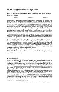
Figure 1: Structure of the system speci�cation each object can exhibit. OO-action systems as well as action systems are intended to be developed stepwise from a high-level speci�cation to an implementation via correctnesspreserving re�nement steps relying on a solid mathematical foundation, the re�nement calculus for action systems �1]. Rather than embody all the requirements in the initial OO-action system speci�cation, we have chosen instead to introduce some of the requirements in successive re�nement steps. Usually, re�nement is used as a way of verifying the correctness of an implementation w.r.t. a speci�cation. But here we also use re�nement as a way of structuring the requirements such that they are easier to validate. The initial OO-action system is intended to model the behaviour of the overall system, that is, the physical environment and the controller together. After some re�nement steps, we separate the controller and the physical environment into two interacting objects, thus arriving at an abstract speci�cation of the controller itself. Further re�nements are made so that we �nally get an implementable control system. Hence, as a satellite result we have derived an OO-action system formalisation of state diagrams. Modelling the environment and the controller as a single action system allows us to abstract away from the communication mechanism between them. For example, all sensors are modelled as attributes which are updated by the environment actions and may be read directly by the controller actions. Only in later re�nement steps do we introduce an explicit mechanism for passing the values of sensors from the environment to the controller. Similarly, device actuators are modelled initially as attributes that are updated by the controller and read by the environment, see Fig. 1. Another reason for modelling the environment is that it allows us to state and use assumptions that we make about how the environment behaves. This approach has been very promising when developing control systems as action systems �6, 16, 17]. Here we extend the technique to cover object-based systems, too. The production cell is a well-known case study �15] on control systems and it has been used as a sort of bench mark for formal methods. Hence, it is used also here to demonstrate the proposed approch. Because of the ease of using object-oriented features when specifying control systems, it 2
became suitable to use UML for obtaining a �rst diagrammatic view over the problem. We speci�cally use the following diagrams: the context and use case diagrams for capturing the interaction of our system with external objects of interest� the class diagram for a �rst approach to our OO system� �nally, the state diagrams for every class of interest. We proceed as follows. In Section 2 we give an UML speci�cation for the production cell using many of the techniques provided by the method. In Section 3 an abstract OO-action systems speci�cation is derived from some of the state diagrams. The plant and the controller objects are separated in Section 4 resulting in a modular structure for the system as depicted in Fig. 1. In Sections 5 and 6 we analyse the attributes in the class diagrams. Some of them model actuators while the others model sensors. These are stepwise introduced into the OO-action system �rst as state attributes then as objects of their own right. We end in Section 7 with some concluding remarks.
2 Initial form of the speci�cation: the UML diagrams In this section we start the speci�cation of the production cell with a collection of UML diagrams based on simple problem statements, i.e. the initial informal speci�cation given by the customer. Because of space considerations, we have included here only the robot and the press. However, the two entities expose a complex behaviour and features like interaction and synchronisation with each other, as well as parallelism. Thereby, this part of the production cell serves well our purposes. We start by considering the press and the robot in isolation. After deriving a collection of diagrams from the informal problem statement, we produce an overall state diagram where we or every class de�ne the points of interest, based on the class attributes and call these points as states. We can give an (invariant) characterisation and an (unique) precondition for every de�ned state. Finally, based on the class diagrams and the overall state diagrams, we notice that states of di erent classes have to be synchronised. Hence, we draw a �nal combined overall state diagram for our classes. 2.1
The Press
The external objects that interact with the system under discussion are called actors within the UML. The speci�cation the customer gives for the press is: `The task of the press is to forge metal blanks. The press consists of two horizontal plates, with the lower plate being movable along a vertical axis. The press operates by pressing the lower plate against the upper plate. Because the robot arms are placed on di erent horizontal planes, the press 3
Press Sensors & Actuators 1: system
Blank Sensor Arm sensor
2:
Position Sensor {up, mid, down} Electric Motor
4: Unload 3: Load
Robot
Figure 2: Context Diagram for the press Press USE CASES: Working
Loading/Receiving
Robot Unloading/Delivering
Figure 3: Use Case Diagram for the press has three positions. In the lower position, the press is unloaded by arm 2, while in the middle position it is loaded by arm 1. The operation of the press is coordinated with the robot arms as follows: 1. Open the press in its lower position and wait until arm 2 has retrieved the metal plate and left the press. 2. Move the lower plate to the middle position and wait until arm 1 has loaded and left the press. 3. Close the press, i.e. forge the metal plate. This process is carried out cyclically' �15]. Hence, we have two basic interactions of the press with one actor, the Robot, namely loading and unloading the press. We show this using a context diagram1 in Fig. 2. The context diagram captures the physical structure of the press and presents it in an object-oriented way. The press is seen as a composite object receiving messages from the external actor - the Robot. Inside the press, the actual system that makes decisions and processes data, uses the sensors and actuators to communicate with the Robot. The latter is initiating the interaction by sending messages to the press. Hence, the Robot is the active partner while the press is the passive one, waiting for the action to be done. Besides the external interactions and the physical structure we need a more logical view over the problem, exposing the primary functionality of the system. This is given by the use case diagram in Fig. 3. From this diagram we can see the interactions with the Robot (Loading and Unloading) also from the press point of view: Receiving and Delivering . This diagram is not a standard UML diagram and it is usually drawn with collaboration diagrams. 1
4
The Press level : {up,mid,down} blank : Boolean arm_inside : Boolean
UnLoad
1
1 The Robot
Figure 4: Class Diagram for the press When the Robot is Loading a blank into the press, this is Receiving it� when the Robot is Unloading a blank from the press, this is Delivering it. Besides, the press has some activity to execute, denoted Working . Because the press is the passive partner in the interaction with the Robot, the former will not modify its internal state until the interaction is done. Thus, none of the press actuators are modi�ed in these interactions. From the point of view of the press, the interaction is done when some of its sensors will inform it so. So far, we have identi�ed some basic services or functions the press will provide. Next we seek for the data it will operate on. Following informal strategies �8] we draw the class diagram in Fig. 4, i.e. the classes, their relationships with each other, and the attributes. The relationship between the classes (UnLoad ) is called an association and it models references from one class to the other. In the eventual implementation it can only be unidirectional, but in the class diagram a bigger degree of generality is allowed. The references are used in the interaction between the instances of the classes. Let us now specify the possible changes in the attribute values. We can represent this using the state diagrams for the press class. The attribute level models the actual position of the lower plate. Given the speci�ed cycle, the possible transitions of this attribute are shown in Fig. 5. Because of the safety requirements in the customer's speci�cation (see points 1 and 2) we have determined other two attributes� arm inside which will check whether or not the robot has an arm inside the press and blank which will check whether or not there is a blank inside the press. The transitions for the last two attributes are also shown in Fig. 5. The Robot is responsible for these changes. The initial value for each attribute is shown with a transition starting in the black �lled circle and ending to that value. The level attribute is modi�ed by the press. We can deduce from here that it is used for modelling the activity of the press, while the other two are used to check some synchronisation conditions with the Robot. We can also deduce the visibility of these attributes from the diagram: while the �rst two will be public in the system, the latter will be private to the press. In this 5
arm_inside [ The Robot retracts its arm ] False
True [ The Robot introduces its arm ] blank [ The Robot delivers a blank ]
False
True
[ The Robot takes a blank ] level
up
[ The press is preparing to deliver a blank ]
[ The press is pressing the blank ] mid
down
[ The press is preparing to receive a blank ]
Figure 5: State Diagram for the press state
Receiving
[ not(arm_inside) /\ blank ]
Pressing
entry: level:=up
[ arm_inside ]
M2R
M2D
entry: level:=mid
entry: level:=down
[ arm_inside ]
[ not(blank) /\ not(arm_inside) ] Delivering
Figure 6: Overall State Diagram for the press phase of the speci�cation we have a precise collection of data (attributes) the press will operate on. We also know the possible changes of value for each attribute. Based on these we can make a semiformal re�nement to the use cases. Namely, we can identify the overall behaviour of the press, discretized on points of interest, called states . We associate to each use case a set of states that re�ne it, by specifying which attributes are changed. Thus we have the following associations: the Receiving and the Delivering use cases correspond to the states having the same names, see Fig. 6. They model the interaction with the Robot. The latter is the active party, while the press just waits for some service to be done for it. The rest of the states (Pressing , M 2D , M 2R ) are re�ning the Working use case. We represent the state changes for the press with a new diagram that we call the overall state diagram, see Fig. 6. We use the acronyms M 2R and M 2D for MoveToReceive and MoveToDeliver respectively. When the internal state is modi�ed by the object itself, this is explicitly shown in the diagram, either within the states or during the transactions, using an assignment statement. When the state is modi�ed due to some interaction with an external object, 6
just the result w.r.t. the behaviour of the object is shown. Each state can be described by a (sub)set of attributes. This characterisation is an invariant over the states. We also give unique preconditions for entering each state. The following table shows the preconditions and invariants for every state of the press. State Receiving Pressing M2D Delivering M2R
Precondition level=mid ^ :blank ^ arm inside level=mid ^ blank ^ :arm inside level=up ^ blank ^ :arm inside level=down ^ blank ^ arm inside level=down ^ :blank ^ :arm inside
Invariant level=mid ^ arm inside :arm inside ^ blank :arm inside ^ blank
level=down ^ arm inside :arm inside ^ :blank
The initial combination of values for the attributes leads the press in the Receiving state, see Fig. 6. In this state the press is waiting until the values of arm inside and blank changes. Also, in order to enter this state, the value of arm inside attribute should be set to true . The same behaviour occurs in the Delivering state. Within the other three states, the local attribute of the press is explicitly modi�ed, modelling the Working algorithm for the press. 2.2
The Robot
The robot is the most complex object in the production cell. The initial statement for it is: `The robot comprises two orthogonal arms. For technical reasons, the arms are set at two di erent levels. Each arm can retract and extend horizontally. Both arms rotate jointly. Mobility on the horizontal plane is necessary, since elevating rotary table, press, and deposit belt are placed at di erent distances from the robot's turning center. The end of each arm is �tted with an electromagnet that allows the arm to pick up metal plates. The robot's task consists in: � taking metal blanks from the elevating rotary table to the press� � transporting forged plates from the press to the deposit belt. The robot is �tted with two arms so that the press cam be used to maximum capacity. Below we describe the order of the rotation operations the robot arm has to perform, supposed the feed belt delivers blanks frequently 7
Robot Sensors & actuators
1: system 2:
Electric Motor 1 Electric Motor 2 Electric Motor 3 Electromagnet 1
6:
Deposit Belt 4: Unload 3: Load
Electromagnet 2 Potentiometer 1
Press
Potentiometer 2 Potentiometer 3
5:
Rotary Table
Figure 7: Context Diagram for the Robot enough. We presuppose that initially the robot is rotated such that arm 1 points towards the elevating rotary table, and assume that all arms are retracted to allow safe rotation. 1. Arm 1 extends, picks up a metal blank from the rotary table, and then retracts. 2. The robot rotates counterclockwise until arm 2 points towards the press. Arm 2 is extended until it reaches the press, then it picks up a forged metal plate and retracts. 3. The robot rotates counterclockwise until arm 2 points towards the deposit belt. Arm 2 extends, places the forged metal blank on the deposit belt, and retracts. 4. The robot rotates counterclockwise until arm 1 points towards the press. Arm 1 extends, deposits the blank in the press and retracts again. 5. Finally, the robot rotates clockwise towards its original position, and the cycle starts again with 1.' �15] Hence, there are three actors interacting with the robot: the Press, the Deposit belt and the Rotary table. The actual system communicates with them via the sensors and actuators. We represent the above information using the context diagram in Fig. 7. We thereby can see the robot as a composite object that interacts with the three actors by sending them messages, i.e., it initiates the interaction. This behaviour was di erent for the press. There the external object was initiating the interaction. This behaviour can also be seen in the use case diagram of Fig. 8 that presents the main functionality of the robot, decomposed in �ve use cases. Four of them correspond to the interactions with the actors, while the �fth is internal to the robot, describing its rotation. The interactions with the Press actor is as follows: it loads/unloads the Press 8
Rotating Robot USE CASES:
RTable
DBelt
Unloading
Loading
ThePress
Figure 8: Use Case Diagram for the robot The Robot hold1 : Boolean 1 UnLoad hold2 : Boolean The Press arm1 : {in, mid, ext} 1 1 arm2 : {in, mid, ext} 1 pos : 1..4
1 The Deposit Belt
1
The Rotary Table
Figure 9: Class Diagram for the robot (Loading =Unloading use cases). As speci�ed in the customer's description, the robot is initiating all these actions, being thus an active partner. At this point we have determined the main functionality of the robot. The class diagram given in Fig. 9 consists of three classes corresponding to the actors and one class corresponding to the robot. The latter is determined with its attributes from the customer's speci�cation. From the robot's point of view, about the other three classes, the only interesting issue is to determine the relationships with them� these will become references to each other. In the eventual implementation the references may be unidirectional. The state diagrams for each attribute of the robot class present their possible changes of value. The attributes hold 1 and hold 2 model the electromagnets on the robot's arms. They control whether or not the respective arm keeps a blank. The attributes arm 1 and arm 2 model the actual position of the respective arm. Finally, the pos attribute controls the current position of the robot, as given in the customer's speci�cation. The possible transitions for all these attributes are given in Fig. 10. For the transitions on the boolean attributes we have specifed some suggestive names. The overall state diagram in Fig. 11 shows explicitly how the attributes are modi�ed. An interesting issue to notice is that the robot is modifying itself its internal state and needs no information from the external objects. Coordination mechanisms with the partners are required, but they are embedded in the external interactions with those, rather than at the internal state level, like it was the case for the press. The di erence comes from the fact the robot is an active partner in the interactions and it should know the identities of the partners. Observe that in the customer's speci�cation the interaction with the rotary table given as initial. We chose the Loading 9
hold1 drops1
arm1
True
False
in
picks1 hold2 drops2 True
False
mid
ext
picks2 3 arm2
pos
in 2
4
mid
ext
1
Figure 10: State Diagram for the robot
state Feeding
arm1:=in
entry: picks1
M2U
arm2:=mid
entry: pos := 2
arm1:=ext
arm2:=in
M2F
M2D
entry: pos := 1
entry: pos := 3
arm1:=in
arm2:=ext Depositing
M2L
Loading
entry: drops1
Unloading
entry: picks2
arm1:=mid
entry: pos := 4
arm2:=in
entry: drops2
Figure 11: Overall State Diagram for the robot
use case (the second interaction with the press) instead as we are interested only in the interactions of the robot with the press. Based on the state diagrams and the initial speci�cation we can determine the overall behavior of the Robot, discretised in eight states which complitely model the requirements given in the customer's speci�cation. We use the acronyms M 2L, M 2F , M 2U and M 2D for MoveToLoad , MoveToFeed , MoveToUnLoad and MoveToDeposit respectively. The invariants and the unique preconditions of the states are shown in the following table. 10
State Feeding M2U Unloading M2D Depositing M2L Loading M2F
Precondition pos=1 ^ arm1=ext ^ arm2=in ^ : hold1 ^: hold2 pos=1 ^ arm1=in ^ arm2=in ^ hold1 ^ :hold2 pos=2 ^ arm1=in ^ arm2=mid ^ hold1 ^ :hold2 pos=2 ^ arm1=in ^ arm2=in ^ hold1 ^ hold2 pos=3 ^ arm1=in ^ arm2=ext ^ hold1 ^ hold2 pos=3 ^ arm1=in ^ arm2=in ^ hold1 ^ :hold2 pos=4 ^ arm1=mid ^ arm2=in ^ hold1 ^ :hold2 pos=4 ^ arm1=in ^ arm2=in ^ :hold1 ^ :hold2
Invariant pos=1 ^ arm1=ext ^ arm2=in ^: hold2 arm1=in ^ arm2=in ^ :hold2 ^ hold1 arm1=in ^ arm2=mid ^ pos=2 ^ hold1 arm1=in ^ arm2=in ^ hold1 ^ hold2 arm1=in ^ arm2=ext ^ pos=3 ^ hold1 arm1=in ^ arm2=in ^ hold1 ^ :hold2 arm1=mid ^ arm2=in ^ pos=4 ^ :hold2 arm1=in ^ arm2=in ^ :hold1 ^ :hold2
Observe that all the attributes are modi�ed in the overall state diagram, i.e., all of them contribute to changes in the internal state of the robot. Now we can associate the states with the use cases as follows. The `moving' states, namely M 2L, M 2F , M 2U , and M 2D re�ne the Rotating use case. The other four states each correspond to the use cases with the same name. The (set of) states indeed re�ne the use cases, as they are speci�ed using attributes and their transitions. 2.3
Synchronisation
Based on the class diagrams in Figs. 4, 9 and the overall state diagrams in Figs. 6, 11, we derived a combined state diagram in Fig. 12. This encompasses both the behaviours of the press and the robot. The �ve states describing the behaviour of the press are shown with the transitions going counterclockwise, while the eight states describing the behaviour of the robot are shown with the transitions going clockwise. The 11
Overall state
Feeding
entry: picks1
arm1:=ext
arm1:=in
M2F
M2U
entry: pos := 1
entry: pos := 2 arm2:=mid
arm1:=in
[ not(blank) /\ not(arm_inside) ] Loading / Receiving
M2R
Unloading / Delivering
entry: level:=mid
entry: picks2
[ arm_inside ]
entry: drops1
arm2:=in
arm1:=mid M2L
M2D
entry: pos := 4
arm2:=ext
arm2:=in
entry: pos := 3
Depositing [ not(arm_inside) /\ blank ]
entry: drops2
[ arm_inside ]
Pressing
M2D
entry: level:=up
entry: level:=down
Figure 12: Combined State Diagram for the press and the robot interesting issue is represented by the common states with the stressed borders. They model the interaction between the objects: when the robot is loading the press, this one is receiving the blank and when the robot is unloading the press, this one is delivering the blank. We can read from the diagram that the arm inside attribute is modi�ed when the arms of the robot either enter or retract the press. In a similar way, the blank attribute is modi�ed when a blank is either dropped or picked into/from the press.
3 The Production Cell as an OO-action system The �rst version of an OO-action system for the Production Cell can be driven directly from the UML class diagrams in Figs. 4, 9 and state diagrams in Figs. 6, 11. On the top-level, we have the components of the production cell: fhProductionCell � PC i � hPress � Pr i� hRobot � R i� : : :g The system consists of a set of classes hc � C i where c is the name of the class and C is its body. Here we focus on the press hPress � Pr i and the robot hRobot � R i. The class hProductionCell � PC i, marked with an asterisk �, is the root class. At execution time one object of this class is initially created and this in turn creates the other objects, below one press object and one robot object, by executing new statements in its body PC : PC = � init new (Press ) � new (Robot ) � ] j
j
12
Both the press and the robot bodies Pr and R , respectively, have a single attribute, state, at this level. The initial states as well as the state changes are deduced directly from the state diagrams of the respective components, see Figs. 6, 11. The class bodies consist of an attribute declaration and initialisation as well as a loop of actions which are chosen for execution in a non-deterministic fashion when enabled. Each action is of the form g ! S where g , a boolean condition on the state attributes, is the guard and S is a statement executed in a state where the guard evaluates to true . The actions are taken to be atomic entities of the system. The semantics of this language is formally de�ned within the weakest precondition calculus elsewhere �2]. Pr = � attr state := Receiving do state = Receiving state := Pressing �] state = Pressing state := MoveToDeliver �] state = MoveToDeliver state := Delivering �] state = Delivering state := MoveToReceive �] state = MoveToReceive state := Receiving j
!
!
!
!
]
!
od
j
R =
� attr do �] �] �] �] �] �] �] od ]
j
state := Loading state = Loading ! state := MoveToFeed state = MoveToFeed ! state := Feeding state = Feeding ! state := MoveToUnload state = MoveToUnload ! state := Unloading state = Unloading ! state := MoveToDeposit state = MoveToDeposit ! state := Depositing state = Depositing ! state := MoveToLoad state = MoveToLoad ! state := Loading
j
The press and the robot objects created above execute their actions in parallel without interfering each others computations. From the combined state diagram in Fig. 12 we can, however, notice that their work must be coordinated at two states: (1) when the robot state is Loading , the press state must be Receiving and (2) when the robot state is Unloading , the press state must be Delivering . This coordination can be introduced by synchronising the two objects at these states. As the robot is the \active" party, we make it to signal the press when entering and leaving these critical states. Technically this coordination is done via two methods, Load and Unload and two associated attributes, load and unload , introduced into the class body Pr of the press. The two methods represent the formalisation of the 13
Load =Unload messages sent to the press in order to perform the interactions, see Figs. 2, 7. The methods are used for the same purpose, i.e. to signal the begin and the end of the interactions. Initially load is set to true , which coincides with the initial press state Receiving , and unload is set to false . Both methods are called by the robot twice during an execution cycle. Let us �rst consider the Load method. This is enabled, i.e., ready to synchronise, either (i) when the press state is Receiving and load holds modelling the state where the robot has fed a blank into the press or (ii) when the press state is MoveToReceive and :load holds modelling the state where the robot is about to feed a blank into the press. Hence, the method is as follows: Load = (:load ^ state = MoveToReceive ! load := true ) �] (load ^ state = Receiving ! load := false )
Similarly for the Unload method we have that the press is willing to synchronise when either (i) its state is MoveToDeliver and :unload holds modelling the fact that the press is about to deliver a pressed blank to the robot or (ii) when the press state is Delivering and unload holds modelling the situation that the robot has removed a blank from the press: Unload = (:unload ^ state = MoveToDeliver ! unload := true )� �] (unload ^ state = Delivering ! unload := false )
The guards of the respective state changes in the press are strenghtened with the load and unload predicates to model the synchronisation in the press actions, i.e., before the state changes from Receiving to Pressing the press must ensure that the robot has called the Load method and placed a blank into the press so that :load holds and similarly for the other press actions interfacing with the robot. The strengthening of the guards in the press body represents a formalisation of the events determining the state transitions in the overall state diagram in Fig. 6. Those events are caused by the robot and just read by the press. We proceed here likewise, by forcing the press to evaluate load or unload before modifying its state attribute. Pr =
�
j
attr state := Receiving � load unload := true false meth Load = Unload = do state = Receiving load state := Pressing �] state = Pressing state := MoveToDeliver �] state = MoveToDeliver unload state := Delivering �] state = Delivering unload state := MoveToReceive �] state = MoveToReceive load state := Receiving od ^:
!
!
^
^:
^
]
j
14
!
!
!
Let us look at the actions in the body of the robot. Four of them need to be modi�ed to re ect the synchronisation. Let p be a pointer to the press object. This pointer is a re�nement of the bidirectional association UnLoad in Figs. 4, 9 modelling an unidirectional association from the robot to the press. When the robot is in the Loading state, it needs to call the Load method of the press before changing its state to MoveToFeed : state = Loading
!
p :Load � state := MoveToFeed
Depending on the state of the press, p :state , and the current value of p :load , the press either sets p :load to true or false . In case the press is not yet in its proper state, the robot must wait. Because actions are atomic, all this activity constitues a single action, i.e., we substitute the body of the called method for the call itself: state = Loading p load p state = MoveToReceive p load := true � state := MoveToFeed �] state = Loading p load p state = Receiving p load := false � state := MoveToFeed ^: :
^
:
!
:
^
:
^
:
!
:
Hence, the robot and the press execute this action jointly forcing them to synchronise. The other actions are constructed in a similar manner. The new robot class body is given below. It contains the method calls as well as a new attribute, the object pointer p to a press object. This attribute is set via the SetPress method: R = � attr state := Loading obj p :Press meth SetPress (sp ) = p := sp do state = Loading p Load � state := MoveToFeed �] state = MoveToFeed state := Feeding �] state = Feeding state := MoveToUnload �] state = MoveToUnload p Unload � state := Unloading �] state = Unloading p Unload � state := MoveToDeposit �] state = MoveToDeposit state := Depositing �] state = Depositing state := MoveToLoad �] state = MoveToLoad p Load � state := Loading j
!
:
!
!
!
!
:
:
!
!
!
od
]
:
j
Finally we need to modify the body PC of ProductionCell to let the robot know about the press, i.e., to set the p pointer in R : PC =
� obj p :Press � r :Robot init p := new (Press ) � r := new (Robot ) � r SetPress (p ) � ] j
:
j
15
The above modi�cations to the original set of classes constitute a re�nement step whose correctness can be formally proved appealing to the transformation rules of the re�nement calculus for OO-action systems �2]. The re�nement calculus is also based on the weakest precondition calculus hence �tting seamlessly with the semantics of OO-action systems. In this paper we do not want to go into details of the semantics of OO-action systems nor those of the re�nement calculus. Intuitively, however, re�nement is done to (i) diminish the non-determinism of a system or (ii) to enlarge the domain of termination for it. Here the re�nement makes the system less non-deterministic disallowing certain executions that were possible in the original system.
4 Separating plant and controller Ultimately, we need to derive a control program for each machine in the production cell. Hence, every state change in the physical plant should be potentially recognised by the control program. We start by separating the plant from the control program for both the press and the robot to exhibit the model depicted in Fig. 1: hProductionCell � PC i � hPress � PPl i� hPressCtrl � PCo i� hRobot � RPl i� hRobotCtrl � RCo i� : : :g
f
The control programs are below modelled by objects created by the plant, that react to state changes via method calls from the plant. Hence, when the plant is about to change its state, the control method corresponding to the state change is called. Now every state change in the plant and the control method in the controller constitute a single atomic action. The state attribute is duplicated so that both the plant and the controller keep track of the current state of the component. PPl =
�
j
]
attr obj init do �] �] �] �] od
state := Receiving p :PressCtrl p := new (PressCtrl ) state = Receiving ! p :Pressing � state := Pressing state = Pressing ! p :MoveToDeliver � state := MoveToDeliver state = MoveToDeliver ! p :Delivering � state := Delivering state = Delivering ! p :MoveToReceive � state := MoveToReceive state = MoveToReceive ! p :Receiving � state := Receiving
j
16
� attr state := Receiving � load unload := true false meth Load = Unload = Pressing = (state = Receiving load state := Pressing ) MoveToDeliver = (state = Pressing state := MoveToDeliver ) Delivering = (state = MoveToDeliver unload state := Delivering ) MoveToReceive = (state = Delivering unload state := MoveToReceive ) Receiving = (state = MoveToReceive load state := Receiving ) ]
PCo =
j
^:
!
!
^
!
^:
^
!
!
j
Also this step is a formal re�nement step in the sense that we rewrite the system by splitting a class into two and add the needed pointers from one to the other for communication purposes. RPl =
� attr state := Loading obj r :RobotCtrl � p :PressCtrl meth SetPress (sp ) = p := sp init r := new (RobotCtrl ) do state = Loading p Load � r MoveToFeed � state := MoveToFeed �] state = MoveToFeed r Feeding � state := Feeding �] state = Feeding r MoveToUnload � state := MoveToUnload �] state = MoveToUnload p Unload � r Unloading � state := Unloading �] state = Unloading p Unload � r MoveToDeposit � state := MoveToDeposit �] state = MoveToDeposit r Depositing � state := Depositing �] state = Depositing r MoveToLoad � state := MoveToLoad �] state = MoveToLoad p Load � r Loading � state := Loading od ] j
!
:
:
!
:
!
:
!
:
:
:
:
!
!
:
!
:
!
:
:
j
17
RCo =
� attr state := Loading meth MoveToFeed = (state = Loading state := MoveToFeed ) Feeding = (state = MoveToFeed state := Feeding ) MoveToUnload = (state = Feeding state := MoveToUnload ) Unloading = (state = MoveToUnload state := Unloading ) MoveToDeposit = (state = Unloading state := MoveToDeposit ) Depositing = (state = MoveToDeposit state := Depositing ) MoveToLoad = (state = Depositing state := MoveToLoad ) Loading = (state = MoveToLoad state := Loading ) ] j
!
!
!
!
!
!
!
!
j
5 Introducing actuators When looking closer at the state diagrams in Figs. 6, 11 we notice that a (sub)set of the objects' attributes as given in the class diagrams are modi�ed by the objects themselves. For the press we have that the level attribute is modi�ed in the states Pressing , MoveToDeliver , and MoveToReceive , see Fig. 5. For the robot we have that all the attributes are modi�ed by it in different situations (states, transitions), as shown in Fig. 10. These attributes constitute the actuators. Therefore we will model them by attributes in the control programs following our approach in Fig. 1. Let us �rst look at the press attribute. The attribute level represents the actuator moving the press. Hence, it is modelled in the body PCo of the controller: PCo = � attr state := Receiving � load unload := true false level UP DOWN MID � meth Load = Unload = Pressing = (state = Receiving load state := Pressing � level := UP ) MoveToDeliver = (state = Pressing state := MoveToDeliver � level := DOWN ) Delivering = (state = MoveToDeliver unload state := Delivering ) MoveToReceive = (state = Delivering unload state := MoveToReceive � level := MID ) Receiving = (state = MoveToReceive load state := Receiving ) ] j
2 f
g
^:
!
!
^
!
^:
^
j
18
!
!
The robot state is characterised via �ve attributes: h 1� h 2 for controlling the electromagnets on the robot's arms, a 1� a 2 for the actual arm positions, and p for the robot position. The values at each state are derived directly from the state diagram for the robot in Fig. 11: RCo =
�
j
]
attr
state := Loading � h 1 h 2 2 fON OFF g � a 1 a 2 2 fin mid ext g � p 2 f1 2 3 4g meth MoveToFeed = (state = Loading ! h 1 := OFF � a 1 := in � state := MoveToFeed ) Feeding = (state = MoveToFeed ! p := 1 � a 1 := ext � state := Feeding ) MoveToUnload = (state = Feeding ! h 1 := ON � a 1 := in � state := MoveToUnload ) Unloading = (state = MoveToUnload ! p := 2 � a 2 := mid � state := Unloading ) MoveToDeposit = (state = Unloading ! h 2 := ON � a 2 := in � state := MoveToDeposit ) Depositing = (state = MoveToDeposit ! p := 3 � a 2 := ext � state := Depositing ) MoveToLoad = (state = Depositing ! h 2 := OFF � a 2 := in � state := MoveToLoad ) Loading = (state = MoveToLoad ! p := 4 � a 1 := mid � state := Loading )
j
These new controllers for the press and the robot re�ne the old ones in the sense that new local data is introduced without changing the overall behaviour of the system. Every actuator can be turned into an object with the needed access methods. Hence, we need one actuator for the press which represents the level. The robot needs four actuators to control the two arms and one actuator to control the rotation. The two electromagnets can be handled by a single class as well as the two potentiometers controlling the arm positions. Hence, we re�ne the set of classes into the following set: f
hProductionCell � PC i � hPress � PPl i� hPressCtrl � PCAi� hRobot � RPl i� hRobotCtrl � RCAi� hActLev � ALe i� hActMag � AMa i� hActPos � ARot i� hActArm � AArm i� : : :g
where the class bodies PCA� RCA of the modi�ed controllers and the new actuators ALe � AMa � ARot � AArm are given below. The attributes of the previous step are turned into object pointers which are initialised at the init-clause. The declarations are moved into the respective actuator bodies and assignments to these attributes are now done via method calls: 19
PCA =
� attr state := Receiving � load unload := true false obj l :ActLev meth Load = Unload = Pressing = (state = Receiving load state := Pressing � l SL(UP )) MoveToDeliver = (state = Pressing state := MoveToDeliver � l SL(DOWN )) Delivering = (state = MoveToDeliver unload state := Delivering ) MoveToReceive = (state = Delivering unload state := MoveToReceive � l SL(MID )) Receiving = (state = MoveToReceive load state := Receiving ) = init l : new (ActLev ) ] j
^:
!
:
!
:
^
!
^:
!
:
^
!
j
ALe =
attr level UP DOWN MID meth SL(l ) = level := l
�
j
2 f
]
g
j
AMa =
� attr magnet ON OFF meth SM (m ) = magnet := m ]
j
2 f
g
j
� attr pos 1 2 3 4 meth SP (p ) = pos := p ]
ARot =
j
2 f
g
j
AArm =
� attr arm in mid ext meth SA(a ) = arm := a ] j
2 f
g
j
The last step of turning the attributes into objects is also a re�nement where we used a similar decomposition method as in Sect. 4. The overall behaviour of the system as a whole is unchanged, but introducing the actuators as objects makes it closer to an implementable distributed system. 20
RCA =
� attr state := Loading obj h 1 h 2:ActMag p :ActPos a 1 a 2:ActArm meth MoveToFeed = (state = Loading h 1 SM (OFF ) � a 1 SA(in ) � state := MoveToFeed ) Feeding = (state = MoveToFeed p SP (1) � a 1 SA(ext ) � state := Feeding ) MoveToUnload = (state = Feeding h 1 SM (ON ) � a 1 SA(in ) � state := MoveToUnload ) Unloading = (state = MoveToUnload p SP (2) � a 2 SA(mid ) � state := Unloading ) MoveToDeposit = (state = Unloading h 2 SM (ON ) � a 2 SA(in ) � state := MoveToDeposit ) Depositing = (state = MoveToDeposit p SP (3) � a 2 SA(ext ) � state := Depositing ) MoveToLoad = (state = Depositing h 2 SM (OFF ) � a 2 SA(in ) � state := MoveToLoad ) Loading = (state = MoveToLoad p SP (4) � a 1 SA(mid ) � state := Loading ) init h 1 := new (ActMag ) � h 2 := new (ActMag )� a 1 := new (ActArm ) � a 2 := new (ActArm ) p := new (ActPos ) ]
j
!
:
:
!
:
:
!
:
:
!
:
:
!
:
:
!
:
:
!
:
:
!
:
:
j
6 Introducing sensors For synchronisation purposes we have introduced two attributes, load and unload , into the press. When we separated the plant and the controller, we have distributed them so that they are set by the plant and read by the controller. Thereby it becomes suitable to model them by sensors following our overall strategy of Fig. 1. However, it is di�cult with a sensor to determine the exact moment the synchronisation should start, as required by the speci�cation. Studying the controllers for the press and robot we have that load = arm inside ^ :blank unload = arm inside ^ blank
Therefore we express the load and unload attributes using the blank and arm inside attributes instead. Moreover, as we will see below, these are easier to map to physical sensors. SRS =
� attr value :Boolean meth RS (v ) = v := value SS (v ) = value := v ] j
j
21
The sensors are modelled directly via a class of their own with two methods for reading and modifying their value, without going via attributes as for the actuators. Here we need two methods, because we explicitly model the changes in sensor readings by assigning the values in the plant speci�cation and subsequently reading them in the controller. The Production Cell also contains a class for the sensors now: f
g
hProductionCell � PC i � hPress � PPl i� hPressCtrl � PCAS i� hRobot � RPlS i� hRobotCtrl � RCAi� hActLev � ALe i� hActMag � AMa i� hActPos � ARot i� hActArm � AArm i� hSensor � SRS i� : : :
Below is the press controller that reads the sensor values in the guards. PCAS = � attr state := Receiving obj l :ActLev a i bl :Sensor meth SetSensors (sai sb ) = a i := sai � bl := sb Load = (state = MoveToReceive skip ) Unload = (state = MoveToDeliver skip ) Pressing = (state = Receiving a i RS bl RS state := Pressing � l SL(UP )) MoveToDeliver = (state = Pressing state := MoveToDeliver � l SL(DOWN ) Delivering = (state = MoveToDeliver a i RS bl RS state := Delivering ) MoveToReceive = (state = Delivering a i RS bl RS state := MoveToReceive � l SL(MID )) Receiving = (state = MoveToReceive a i RS bl RS state := Receiving ) init l := new (ActLev ) ] j
!
!
^:
:
^
:
!
:
!
:
:
^
^:
:
^
^:
:
!
:
!
:
^
:
^:
:
!
j
In the press controller we thus replaced load and unload attributes with their equivalents in the guards of the Delivering and Receiving methods. However, for the MoveToReceive and Pressing methods the situation is not this clear, because :load = :arm inside _ blank and :unload = :arm inside _:blank giving us three alternative replacements. When consulting our state diagram in Fig. 12 we deduce that :load should be replaced by :arm inside ^ blank and :unload by :arm inside ^ :blank . The Load and Unload methods have also changed re ecting the new situation. The synchronisation at the Receiving respective Delivering states 22
is now completely handled by the sensors. However, when originally :load or :unload holds, we need to be careful. The sensor values do get changed by the robot plant when the robot is about to interact with the press. However, we still need to synchronise with the press to ensure that this is in the MoveToReceive or MoveToDeliver state. RPl =
� attr obj meth init
j
do �] �] �] �] �] �] �] ]
od
state := Loading r :RobotCtrl � p :PressCtrl � arm blk :Sensor SetPress (sp ) = p := sp r := new (RobotCtrl ) � arm := new (Sensor )� arm :SS (false ) � blk := new (Sensor )� blk :SS (false ) � p :SetSensors (arm blk ) state = Loading ! r :MoveToFeed � arm :SS (false )� bl :SS (true ) � state := MoveToFeed state = MoveToFeed ! r :Feeding � state := Feeding state = Feeding ! r :MoveToUnload � state := MoveToUnload state = MoveToUnload ! p :Unload � r :Unloading � arm :SS (true )� bl :SS (true ) � state := Unloading state = Unloading ! r :MoveToDeposit � arm :SS (false )� bl :SS (false ) � state := MoveToDeposit state = MoveToDeposit ! r :Depositing � state := Depositing state = Depositing ! r :MoveToLoad � state := MoveToLoad state = MoveToLoad ! p :Load � r :Loading � arm :SS (true )� bl :SS (false ) � state := Loading
j
At this stage of the design the synchronisation is modelled via calls to the methods whose only actual e ect for the press controller will be this synchronisation as the bodies of the methods are skip statements. In later steps this synchronisation is done via new sensors in the press. We, however, skip this here as the re�nement follows a similar pattern as above. Observe that all the above re�nements are proper re�nements as we have used equivalencies to rewrite guards, decompositions to split classes, and diminished the amount of non-determinism by removing two alternative branches of methods. 23
7 Concluding remarks We have shown how informal and formal methods can interplay in the design of a distributed control system. The main advantage we gain with the UML diagrams is the identi�cation of di erent entities needed for the formal speci�cation. Moreover, complexity in the formal speci�cation can be stepwise added by getting inspiration from details in the diagrams. This allows us to keep the formal speci�cation very abstract in the beginning and elaborate it in manageable portions. We also believe that the UML diagrams are of use in later stages of the life time of the system as they completely re ect and clarify the structure of the formal speci�cation this one being non-trivial when all the requirements are speci�ed. Eventhough we were not very formal in doing the re�nement steps in this paper all the proofs can be formalised and carried out within the re�nement calculus. Moreover, as a bonus we have arrived at a complete formalisation of state diagrams as OO-action systems as given by our �nal set of classes. The production cell case study has been speci�ed formally within several formalisms �15]. Our formalisation follows the ideas of Sekerinski �17] except that we have extended our previous design methods to cover an object-based approach. The main focus in this paper has, however, been on the mixture of informal and formal techniques.
Acknowledgments. The work of Kaisa Sere is supported by the Academy of Finland.
References �1] R.J.R. Back and K. Sere. From Action Systems to Modular Systems. Software - Concepts and Tools. 1996. �2] M. Bonsangue, J.N. Kok, and K. Sere. An approach to objectorientation in action systems. Proceedings of Mathematics of Program Construction (MPC'98), Marstrand, Sweden, June 1998. Lecture Notes in Computer Science 1422. Springer Verlag. �3] G. Booch. Object-Oriented Design. In Ada Letters. Vol. I, No. 3, March-April 1982, pp. 64-76. �4] G. Booch, J. Rumbaugh, and I. Jacobson. The Uni�ed Modeling Language User Guide. Addison-Wesley, October 1998. �5] R. Breu, U. Hinkel, C. Hofmann, C. Klein, B. Paech, B. Rumpe, V. Thurner. Towards a Formalization of the Uni�ed Modeling Language. In Proceedings of ECOOP'97. Jyv�askyl�a, Finland, June 1997. Lecture Notes in Computer Science 1241. Springer Verlag. 24
�6] M. Butler, E. Sekerinski, and K. Sere. An Action System Approach to the Steam Boiler Problem. In Jean-Raymond Abrial, Egon Borger and Hans Langmaack, editors, Formal Methods for Industrial Applications: Specifying and Programming the Steam Boiler Control. Lecture Notes in Computer Science Vol. 1165. Springer-Verlag, 1996. �7] K.M. Chandy and J. Misra. Parallel Program Design: Foundation.Addison-Wesley, 1988.
A
�8] B. P. Douglass. Real-Time UML: Developing E cient Objects for Embedded Systems. Addison-Wesley, 1998. �9] D. Harel. Statecharts: A Visual Formalism for Complex Systems. In Science of Computer Programming 8(1987): 231-274. �10] I. Jacobson, M. Christerson, P. Jonsson, and G. O� vergaard. ObjectOriented Software Engineering: A Use Case Driven Approach. Addison-Wesley, Reading, Massachusetts, 1992. �11] V. Kasurinen. Informal and Formal Requirements Speci�cation. PhD Thesis, University of Kuopio, Department of Computer Science and Applied Mathematics, 1999. �12] V. Kasurinen and K. Sere. Data Modelling in ZIM. Proc. of Methods Integration'96, Leeds, UK, 1996. In A. Bryant and L. Semmens, eds., Method Integration, electronic workshops in Computing, July 1996. Springer Verlag. �13] R. Kneuper. Limits of Formal Methods. Formal Aspects of Computing 9(4): 379-394, Springer Verlag 1997. �14] L. P. Gorm, N. Plat, and H. Toetenel. A formal semantics of data
ow diagrams. Formal Aspects of Computing 6(6): 586{606, Springer Verlag 1994. �15] C. Lewerentz and Th. Lindner (eds). Formal Development of Reactive Systems - Case Study Production Cell. Lecture Notes in Computer Science 891, Springer-Verlag 1995. �16] M. R�onkk�o, E. Sekerinski, and K. Sere. Control Systems as Action Systems - A Case Study. In Proc. of Workshop on Discrete Event Systems, Edinburgh, UK, August 1996. �17] E. Sekerinski. Production Cell. In E. Sekerinski and K. Sere (editors). Program Development by Re�nement { Case Studies Using the B Method. FACIT, Springer-Verlag 1998. 25
�18] M. Weber. Combining Statecharts and Z for the Design of SafetyCritical Systems. In Proc. of FME'96 - Industrial Bene�t and Advances in Formal Methods. Lecture Notes in Computer Science 1051, Springer Verlag, 1996.
26
Turku Centre for Computer Science Lemminkaisenkatu 14 FIN-20520 Turku Finland http://www.tucs.abo.�
University of Turku Department of Mathematical Sciences
Abo Akademi University Department of Computer Science Institute for Advanced Management Systems Research
Turku School of Economics and Business Administration Institute of Information Systems Science