Hans-Joachim Wunderlich ... lower random pattern testability than stuck-at faults and this increases the need for a DLBIST ... (transition) faults and stuck-at faults.
DLBIST for Delay Testing Valentin Gherman, Hans-Joachim Wunderlich
Michael Garbers, Jürgen Schlöffel
Universität Stuttgart Pfaffenwaldring 47 D-70569 Stuttgart, Germany
Philips Semiconductors GmbH Georg-Heyken-Strasse 1 D-21147 Hamburg, Germany
(wu, ghermanv)@informatik.uni-stuttgart.de
(michael.garbers, juergen.schloeffel)@philips.com
Abstract Due to its inherent support for at-speed test, BIST is an attractive approach to test delay faults. Deterministic logic BIST (DLBIST) is a technique which was successfully applied to enhance the quality of BIST in the case of stuck-at test. The test of delay faults requires the application of pattern pairs. Consequently, delay faults have a lower random pattern testability than stuck-at faults and this increases the need for a DLBIST scheme. On the other hand, a DLBIST solution is expected to require a larger mapping effort and logic overhead than in the case of stuck-at test. In this paper, we present the extension of a DLBIST scheme which becomes available for the test of both delay (transition) faults and stuck-at faults. Functional justification is used to generate the pattern pairs required by the target delay faults. We investigate the efficiency of the extended scheme in the case of some industrial benchmarks.
Keywords: Deterministic logic BIST, delay test.
1. Introduction The steady increase of clock rate and integration density enhances the relevance of defects covered by delay fault models [1]. We distinguish two basic types of delay faults: local delay faults caused by local disturbances [5] of the fabrication process (spots) and global delay faults generated by global disturbances [11], which are traditionally associated to gate, respectively path delay faults [7] and segment delay faults [3][6]. A simplification of the gate delay fault model is the transition fault model [10] which assumes a length of the signal perturbation of the same order of magnitude as the clock period. The transition fault model associates to each line of the core under test (CUT) two faults: slow-to-rise and slow-to-fall. In order to test delay faults, two patterns are required, an initialization pattern that sets the circuit to a predefined state, and an activation pattern that launches the appropriate transition and propagate the fault effect to a primary output. In the case of standard scan designs, there are two distinct approaches for the application of pattern pairs: functional justification, also called broadside, and scan shifting, also called skewed-load. In the functional justification approach, the circuit response to the first pattern is used as the second pattern. In order to apply pattern pairs, the circuit is operated in functional mode two consecutive clock cycles after the first pattern was shifted in. In the scan shifting approach, the second pattern is generated out of the first one by operating the scan path one additional shift clock cycle. Since scan shifting may require additional efforts for a consistent clocking scheme beyond the BIST hardware, here we will concentrate only on functional justification. There is a wide range of deterministic logic BIST (DLBIST) methods that apply deterministic test patterns and hence improve the low fault coverage often obtained by pseudo-random patterns. Very attractive schemes, which require no interaction with the ATE during test application time, are the, so called, test set embedding schemes. These rely on a pseudo-random test pattern generator plus some additional circuitry that modifies the pseudorandom sequence in order to embed a set of deterministic patterns. Examples for such techniques are bit-fixing [9] and bit-flipping [2][4][12] DLBIST schemes. The synthesis of these schemes requires first the mapping of a set of deterministic patterns to an initial pseudo-random sequence and the synthesis of the circuitry used to embed the target patterns [2]. Here, the bit-flipping DLBIST scheme used for the test of stuck-at faults will be adapted for the test of transition faults based on functional justification. As long as ATPG and fault simulation support the test of transition faults, the extension of the DLBIST scheme for stuck-at faults consists only in modifying the test control unit (see next section) such that the scan enable signal covers two clock cycles and not one as in the case of stuck-at test.
The challenge is that, due to the fact that pattern pairs are required, the pseudo-random fault coverage for delay faults is lower than for stuck-at faults. Consequently, the mapping effort and the logic overhead of DLBIST required by the test of transition faults are expected to be larger than for the test of stuck-at faults. As a solution, this paper proposes a trade-off between these costs and the test application time. Slightly larger test application times would reduce logic overhead and enhance test quality in terms of both transition fault and defect coverage [8]. The next section summarizes the bit-flipping approach for the test of stuck-at faults. An approach to extend this scheme for the test of transition faults is described in Section 3. Relevant experimental results for some large industrial designs are reported in Section 4. Finally, Section 5 concludes this work.
2. Bit-flipping Deterministic Logic BIST (DLBIST) for stuck-at faults The bit-flipping DLBIST scheme provides both pseudo-random and deterministic test patterns. Some of the pseudo-random patterns generated by an LFSR, are altered into deterministic test patterns. Most of the pseudorandom test patterns do not contribute to the fault coverage, since they only detect faults that already were detected by other pseudo-random patterns. Such useless pseudo-random test patterns may therefore be skipped or modified in any arbitrary way. The key idea is to modify some useless pseudo-random patterns into useful deterministic test patterns to improve the fault coverage. The deterministic test patterns are determined by an ATPG tool, and they target those faults that are not detected by pseudo-random test patterns. In such a deterministic test pattern, only few bits are actually specified, while most of the bits are don’t care and hence can arbitrarily be set to 0 or 1. The modification of the pseudo-random patterns is realized by inverting (flipping) some of the LFSR outputs, such that the deterministic patterns are obtained. The flipping is performed by combinational logic, which implements a so-called bit-flipping function (BFF). The BFF can be kept quite small by exploiting the large number of useless pseudo-random test patterns that may be modified, and carefully selecting the pseudo-random test patterns on which deterministic test patterns are mapped.
L F S R + P S
xor
Scan Chain 1
xor
Scan Chain 2 Core Logic
xor
CRL
Scan Chain n
M I S R
Pattern Counter Test Control Unit
BFF
Shift Counter
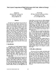
Figure 1. Architecture of the bit-flipping DLBIST. As shown in Figure 1, the BFF inputs are connected to the LFSR, the pattern counter (PC), and the shift counter (SC), while the BFF outputs are connected to the XOR-gates at the scan inputs. The BFF determines whether a bit has to be flipped based on the states of the LFSR, the pattern counter and the shift counter. The pattern counter is part of the test control unit, and counts the number of test patterns applied during the self-test. The shift counter is also part of the test control unit, and counts the number of scan shift cycles for shifting data in/out the scan chains. If a phase shifter (PS) is attached to the LFSR, its output is used to control the operation of the BFF, as well. A correction logic (CRL) is preventing that useful patterns of the pseudo-random sequence are destroyed by the BFF. The BFF realizes the mapping of deterministic test patterns to pseudo-random patterns. Every specified bit (i.e. care bit) in a deterministic pattern either matches to the corresponding bit in the pseudo-random pattern, in which case no bit-flipping is required, or the bit does not match, in which case bit-flipping is required. For all unspecified bits (i.e. don’t-care bits) in the deterministic pattern, the corresponding bits in the pseudo-random pattern may be arbitrarily flipped or not. The BFF should provide that (1) all conflicting bits are flipped, (2) all matching bits are not flipped while (3) the don’t-care bits may be arbitrarily flipped or not. A BDD-based
method for the generation and the logic implementation of the BFF that scales well with the CUT size is described in [2]. At the end of the test, a signature will be stored into a Multi-Input Shift Register (MISR), containing the information about the correctness of the tested core. In order to obtain a not corrupted signature, the logic of the circuit should be BIST-ready, which is equivalent with ensuring that no Xs (unknowns) are generated. If that is not possible an X-masking logic [8] should be inserted before the MISR.
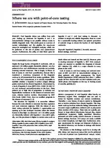
3. Bit-flipping Deterministic Logic BIST (DLBIST) for transition faults In order to extend the bit-flipping scheme such that transition faults may be tested, the DLBIST hardware is modified such that pattern pairs can be applied to the CUT and deterministic patterns for transition faults are embedded into the pseudo-random sequence. These patterns are generated by a CAT tool supporting both ATPG and fault simulation (FS) for transition faults based on functional justification. In such a scheme only the first pattern (initialization pattern) of each pattern pair should be generated by the DLBIST hardware. The second pattern (activation pattern) is generated by the CUT as a response to the first pattern and consequently only single test cubes have to be embedded. Consequently, the resulting CAT flow is similar to the one used for stuck-at faults in [2], just ATPG and FS are changed. The only modification of the BIST hardware used for stuck-at faults concerns the test control unit (see Figure 1), which must be able to provide pairs of functional (capture) clock cycles. The challenge in applying this DLBIST scheme to transition faults is due to their lower random testability which requires more patterns with more specified bits to be embedded into the pseudo-random sequence. For example, consider the circuit in Figure 2. The inputs of this circuit are driven by 4 scan flip-flops. A scan enable signal (SE) is used to switch the scan flip-flops between scan and functional mode. Possible patterns to test the stuck-at faults at line j are abcd ∈ {1XXX, X11X}, for the stuck-at 0 fault, and abcd ∈ {00XX, 0X0X}, for the stuck-at 1 fault (see Figure 2). Based on functional justification, the initialization pattern abcd = 0011 will generate an activation pattern 0111 such that a slow-to-rise transition fault at line j can be tested. The initialization pattern required for the transition fault has more specified bits than the patterns for the stuck-at test. This increase in the number of specified bits is due to the fact that the initialization pattern must not only set the required initial logic value on the target line, but also generate appropriate logic values at the CUT outputs in order to define a useful activation pattern. The slow-to-fall transition fault on the line j cannot be tested. SE SI FF1
a
FF2
b
≥1 ≥1
FF3
c
&
FF4
d
&
e &
h
j ≥1
k
Patterns which can test the stuck-at 0 (sa-0), stuck-at 1 (sa-1) and slow-torise faults on the wire j: sa-0
sa-1
1 X X X
0 0 X X
slow-to-rise
f g
=1
i
a b c d
X 1 1 X
0 X 0 X
0 0 1 1
SO
Figure 2. Specified bits for testing stuck-at and transition faults.
4. Experimental results In this section we investigate the application of the considered DLBIST scheme for the FJ-based test of transition faults and the impact of increasing the test length on the hardware overhead. The experimental results reported below were performed on Linux GNU machines equipped with 2 GB of memory and an Intel Pentium 4 processor running at 2.4 GHz. The benchmark circuits are industrial designs described in Table 1. The first column reports the circuit name encoded like pN, where N denotes the number of nodes in the design. The next two columns give the number of
scan flip-flops and scan chains contained by each design. The following column shows the length of the test sequence. The next column reports the pseudo-random stuck-at fault efficiency. The used tool defines the fault efficiency as the percentage of detected and redundant faults, with respect to the total number of faults. The last column gives the fault efficiency obtained in the case of transition fault testing. For each design, the last entry line corresponds to a test sequence whose application would require 1 second at the frequency of 100MHz. One can easily observe that the fault efficiency of the transition faults is much lower and, in general, the impact of increasing the length of the test sequence is larger in the case of transition faults than in the case of stuck-at faults. Design
# Flip-flops # Scan chains Test length Random stuck-at fault efficiency [%] Random transition fault efficiency [%]
p19K
1407
p59K
29
4730
p127K
20
5116
11
10K
75.20
47.64
32K
79.60
53.43 56.23
64K
84.10
1923K
89.19
58.53
10K
88.11
63.56
32K
88.85
66.48
64K
89.01
67.78
192K
89.22
69.54
10K
82.59
54.48
32K
87.46
63.23
64K 187K
89.66 92.38
66.88 72.03
Table 1. Benchmark characteristics. In Table 2, one can compare the results obtained using the bit-flipping DLBIST approach for the test of the stuck-at and transition faults of the benchmarks from Table 1. One can observe that in all the cases the obtained stuck-at fault efficiency is much larger than the transition fault efficiency. This higher efficiency was achieved while, with the exception of the first design, also the cell area overhead of the stuck-at test is lower. The reason for this difference is the lower random testability of the transition faults with the consequence that more patterns should be embedded and more bits should be flipped or preserved in the pseudo-random sequence. This seems to be not the case of the p19K design, but here it was just the ATPG that provided fewer patterns to be mapped in the case of transition faults than in the case of stuck-at faults. Stuck-at fault test Design
Transition fault test
Ratio of Ratio of # Embedded Final fault # Embedded Cell area [%] patterns specified bits [%] efficiency [%] patterns specified bits [%]
Final fault efficiency [%]
Cell area [%]
p19K
181
26.48
99.26
25
145
10.64
96.39
17
p59K
137
2.77
99.19
4
1077
03.00
97.21
26
p127K
582
12.04
99.27
22
800
15.24
76.89
43
Table 2. DLBIST applied to stuck-at and transition fault test, in the case of a 10K patterns long test sequence. Design Test length # Embedded patterns Run-time [h:m] Memory [MB] Final fault efficiency [%] Cell area [%]
p19K
p59K
p127K
10K
145
00:16
58
96.39
17
32K
125
00:24
61
96.39
11
64K
105
00:23
67
96.39
7
1923K
54
04:01
577
96.40
4
10K
1077
07:22
252
97.21
26
32K
942
06:19
240
97.31
20 18
64K
865
05:45
230
97.39
192K
738
05:53
286
97.44
15
10K
800
32:55
716
76.89
43
32K
800
32:09
738
82.63
44
64K
800
31:47
755
85.34
44
187K
800
30:17
786
88.04
42
Table 3. Results obtained with the bit-flipping DLBIST used for transition fault testing.
The impact of increasing the test length on the overhead of the considered DLBIST scheme, applied to the test of transition faults, can be observed in Table 3. As a performance measure we give the computational requirements (run-time and memory) and the effectiveness of the resulting hardware in terms of achieved fault efficiency and cell area overhead of the BFF+CRL (see Figure 1) with respect to the cell area of the considered core. As expected, the hardware overhead of the first 2 designs (for which the number of embedded patterns was not limited) is significantly reduced by the increase of the test length. The test length has a strong impact on the BFF+CRL overhead of both designs. Extending the test length from 10K to 64K is reducing the BFF+CRL overhead with around 10% of the CUT size. In the case of the last entry corresponding to the design ‘p19K’, increasing the test length by two orders of magnitude has reduced the BFF+CRL overhead to half of its level from the previous entry, at the price of a very large increase of the run-time and memory requirements. For the experiments performed with the design ‘p127K’ the maximum number of embedded patterns was limited to 800 (in order to limit the BFF overhead). Consequently, increasing the test length doesn’t significantly change the BFF+CRL overhead, but it significantly improves the final fault efficiencies.
5. Conclusions We presented an extension of the bit-flipping DLBIST approach to transition faults. This extension is based on the functional justification for delay testing and on the BDD-based calculus used for the generation and optimization of the BFF, described in detail in [2]. Due to the rather low random-pattern testability of delay faults, the saturation of the fault coverage requires significantly longer random test sequences, which in turn is beneficial for both limiting the hardware overhead and improving the coverage of non-modeled faults.
Acknowledgments This research work was supported by the German Federal Ministry of Education and Research (BMBF) in the Project AZTEKE under the contract number 01M3063C.
References [1] J.T.-Y. Chang, E.J. McCluskey “Detecting Delay Flaws by Very-Low-Voltage Testing,” Proceedings of International Test Conference, 1996, pp. 367-376. [2] V. Gherman, H.-J. Wunderlich, H. Vranken, F. Hapke, M. Wittke, M. Garbers “Efficient Pattern Mapping for Deterministic Logic BIST,“ IEEE International Test Conference, 2004, pp.48-56. [3] K. Heragu, J.H. Patel, V.D. Agrawal “Segment delay faults: a new fault model,” Proceedings of VLSI Test Symposium, 1996, pp. 32-39. [4] G. Kiefer, H. Vranken, E.J. Marinissen, H.-J. Wunderlich “Application of Deterministic Logic BIST on Industrial Circuits,” Proceedings of International Test Conference, Atlantic City, NJ, October 3-5, 2000, pp. 105-114. [5] G.M. Luong, D.M. Walker “Test Generation for Global Delay Faults,” Proceedings of International Test Conference, 1996, pp. 433-442. [6] M. Sharma, J.H. Patel “Enhanced Delay Defect Coverage with path-Segments,” Proceedings of International Test Conference, 2000, pp. 385-392. [7] G.L. Smith “Model for Delay Faults based upon Paths,” Proceedings of International Test Conference, 1985, pp. 342-349. [8] Y. Tang, H.-J. Wunderlich, H. Vranken, F. Hapke, M. Wittke, P. Engelke, I. Polian, B. Becker “X-Masking During Logic BIST and Its Impact on Defect Coverage,“ International Test Conference, IEEE, 2004, pp.442451. [9] N.A. Touba, E.J. McCluskey “Altering a pseudo- random bit sequence for scan-based BIST,” Proceedings IEEE International Test Conference, 1996, pp.167-175. [10]J.A. Waiacukauski, E. Lindbloom, B.K. Rosen, V.S. Iyengar “Transition Fault Simulation,” IEEE Design & Test of Computers, 1987. [11]D.M.H. Walker “Tolerance of delay faults,” Proc. of the 1992 IEEE International Workshop on Defect and Fault Tolerance in VLSI Systems, 1992, pp. 207-216. [12]H.-J. Wunderlich, G. Kiefer “Bit-Flipping BIST,” Proceedings International Conference on Computer Aided Design, IEEE, 1996, pp. 337-343.