between a full-size GFRP beam and a GFRP coupon, the full-size beam ... of pultruded GFRP beams is different from the coupon flexural modulus, and the ...
Prakash Kumar, K. Chandrashekhara and Antonio Nanni, “Testing and Evaluation of Components for a Composite Bridge Deck,” Journal of Reinforced Plastic s and Composites, March 2001.
TESTING AND EVALUATION OF COMPONENTS FOR A COMPOSITE BRIDGE DECK
Prakash Kumar and K. Chandrashekhara Department of Mechanical and Aerospace Engineering and Engineering Mechanics
and Antonio Nanni Department of Civil Engineering University of Missouri – Rolla Rolla, MO 65409
1
Prakash Kumar, K. Chandrashekhara and Antonio Nanni, “Testing and Evaluation of Components for a Composite Bridge Deck,” Journal of Reinforced Plastic s and Composites, March 2001.
ABSTRACT
In this paper the results of an experimental investigation conducted on 76 mm (3 in) square hollow pultruded glass fiber-reinforced polymer (GFRP) tubes and their assemblies have been discussed. These GFRP tubes are used in the fabrication of an allcomposite bridge deck that is designed for H-20 truckloads as specified by the American Association of State Highway and Transportation Officials (AASHTO). The study is principally focused on the experimental characterization of flexure performance under static loading of pultruded GFRP tubes made of unidirectional glass fibers. Several tests were conducted on single GFRP tubes followed by combinations of two tubes and a fourlayered tube assembly. The tubes were bonded together using epoxy adhesive to build the assembly.
The specimen details, experimental setup and instrumentation, testing
procedure, failure modes and the test results of these experiments have been discussed in detail. A preliminary design model of each test coupon was developed and analyzed using Finite Element Analysis (FEA). Experiments were conducted to corroborate the analytical design model. Comparison between the theoretical and experimental results showed good correlation. Experimental results show excellent linear elastic flexural and shear behavior up to failure. The stiffness of the tubes and their assemblies demonstrate that they can be used in the building of all-composite bridge decks and for other infrastructure applications. Failure modes for the samples under static flexural loads are described. Key Words: Glass Fiber-Reinforced Polymer (GFRP), Composite, Pultrusion, Bridge Deck, Finite Element Analysis (FEA). 1. INTRODUCTION The construction and infrastructure industry has used conventional composite materials (e.g. reinforced concrete) for many years because they perform better than the constituents themselves and better than competing homogeneous materials. Advanced composite materials like fiber-reinforced polymers (FRP) have been increasingly gaining the interest of researchers and engineers as attractive alternatives to conventional materials used in civil engineering due to their unique properties such as high strength-to2
Prakash Kumar, K. Chandrashekhara and Antonio Nanni, “Testing and Evaluation of Components for a Composite Bridge Deck,” Journal of Reinforced Plastic s and Composites, March 2001.
weight ratio, excellent corrosion and fatigue resistance, manufacturing flexibility, tailoring of the material to specific applications, modular construction and overall environmental durability (Liskey (1991)).
Their use is growing significantly in
construction and infrastructure applications where durability and corrosion resistance are required due to the introduction of low-cost polyester resins and glass fiber-reinforced polymers (GFRP).
Several writers (Karbhari et al. (1997) and Aref and Parsons (1996)) have documented the deteriorating condition of bridges and other infrastructure facilities all over United States in recent years. This growing concern has prompted civil engineers to consider alternatives for conventional materials. In this effort to find a way to extend the life of structures and to make them easier to construct and maintain, the use of FRP materials has been recommended (Zureick et al. (1995)). One of the present areas of emphasis is the use of composite materials for the fabrication of lightweight bridge decks that can be deployed for replacement of deteriorating ones or for the erection of new ones. However, the application of composite materials to infrastructure has been limited due to the lack of material property uniformity or consistency, industry-recognized design criteria and standardized test methods as shown by Ballinger (1990). The introduction of mass-produced FRP structural shapes in bridges and highway applications dictates the necessity for a more complete understanding of the static behavior of these shapes for the types of load and strain ranges that are typically anticipated so as to optimize the design and evaluation techniques.
Bank (1989) showed that because of the difference in mechanical properties between a full-size GFRP beam and a GFRP coupon, the full-size beam flexural modulus of pultruded GFRP beams is different from the coupon flexural modulus, and the coupon flexural modulus also differs from the coupon longitudinal modulus.
Due to these
differences, it becomes necessary to conduct tests and study the behavior of full-size GFRP beams at component or beam level in addition to coupon level. Nagraj and Ganga Rao (1993) have characterized the behavior of pultruded GFRP box beams under static and fatigue or cyclic bending loads. The tests showed that the shear and interfacial slip
3
Prakash Kumar, K. Chandrashekhara and Antonio Nanni, “Testing and Evaluation of Components for a Composite Bridge Deck,” Journal of Reinforced Plastic s and Composites, March 2001.
between adjacent layers had significant influence on deflection and strain measurements. Davalos and Qiao (1997) conducted a combined analytical and experimental evaluation of flexural-torsional and lateral-distortional buckling of FRP composite wide-flange beams. They also showed that in general buckling and deflections limits tend to be the governing design criteria for current FRP shapes. The structural efficiency of pultruded FRP components and systems in terms of joint efficiency, transverse load distribution, composite action between FRP components, and maximum deflections and stresses was analyzed by Sotiropoulos et al. (1994) by conducting experiments on several components.
Structural performance of individual FRP components was established
through three- and four-point bending tests. Barbero et al. (1991) gave a theoretical determination of the ultimate bending strength of GFRP beams produced by pultrusion process.
Several I-beams and box beams were tested under bending and the failure
modes have been described.
The simultaneous determination of flexural and shear
moduli using an experimental method by three-point bending has been done by Fisher et al. (1981). The behavior of pultruded GFRP wide flange and box beams under static loads has been studied by Nagraj and Ganga Rao (1997).
They also developed
theoretical methods for bending and shear stiffness computations and compared them with experimental results.
Although structural engineers have a wide range of pultruded GFRP structural shapes, made of glass fibers and resins (polyester, vinyl ester, epoxy), at their disposal, the focus of this study is to provide structural design information pertaining to mechanical properties and failure modes of square hollow pultruded tubes made of glass fibers in vinyl ester resin when used as a primary load bearing member. The study also investigates the influence of shear, buckling, initial crookedness, and manufacturing defects (material non-uniformity or asymmetry) on the structural behavior of GFRP hollow tubes. Special emphasis is given to understand the modes of failure under static loading. Several coupons consisting of single, double and a four-layered tube assembly were tested under static flexural loading. The coupons consisted of 76 mm (3 in) square hollow pultruded GFRP tubes with a thickness of 6.35 mm (0.25 in). The coupons were tested to failure under flexural loading and data obtained for deflection and strain were
4
Prakash Kumar, K. Chandrashekhara and Antonio Nanni, “Testing and Evaluation of Components for a Composite Bridge Deck,” Journal of Reinforced Plastic s and Composites, March 2001.
evaluated.
The results obtained were compared with those from the finite element
analysis (FEA). The stress distribution and modes of failure, determined by the tests, were verified numerically. The validation model allows one to investigate feasibility of the design and to predict the behavior of the bridge. The knowledge and data gained from these tests will be used to analyze the response of the GFRP composite materials and of various assemblies built out of it, especially with regard to bridge deck applications. 2. DETAILS OF THE GFRP TUBES USED The GFRP tubes used for the tests were manufactured using a pultrusion process. This process involves the pulling of reinforcing fibers and resin matrix through a die that shapes and cures the material. Pultruded composite members are being used extensively as beams in structural applications.
It offers many distinct advantages for mass
production of FRP tubes to be used for the composite bridge deck, such as low operating costs, high production rate, product reproducibility and dimensional tolerances. Dry tows of FRP were pulled through a resin bath before being drawn into a die. Standard vinyl ester resin was used for this application. Aluminum Trihydrate (ATH), a common flame retardant, was used along with the resin. In case of fire, ATH releases water and thus prevents the fire from spreading or damaging the structure. The cured tubes were pulled out of the die using a mechanism of two intermittent clamps to give a continuous pulling action. Each of these clamps grips on the forward stroke and releases on the backstroke. A cut-off saw was used to obtain tubes of appropriate lengths.
The tubes manufactured for testing had a fiber volume fraction of fifty-five percent. The fibers consist of continuous strand fiberglass mat and fiberglass rovings with fifty percent by volume fiberglass mat and fifty percent fiberglass roving. The mat was laid down on the outside, middle and inside of the tube while the rest consisted of fiberglass rovings. The unidirectional continuous strand fiberglass rovings, laid down along the axis of the tube, were responsible for providing the longitudinal mechanical properties, while the continuous strand fiberglass mat provided the transverse properties of the tubes (Agarwal and Broutman (1990)). Coupons were cut out from a tube in 00, 5
Prakash Kumar, K. Chandrashekhara and Antonio Nanni, “Testing and Evaluation of Components for a Composite Bridge Deck,” Journal of Reinforced Plastic s and Composites, March 2001.
900 and 450 fiber orientation, were tested in tension and the moduli were determined for all the three cases.
This helped to determine the material properties of the GFRP
composite used for manufacturing the tubes and to verify the accuracy of the micromechanical used to predict composite properties from the material properties of the constituents (fiber ands resin). The modulus in the zero, ninety and forty-five degree fiber directions were 21.38 GPa (3,100 ksi), 8.2 GPa (1,190 ksi) and 7.05 GPa (1,023 ksi) respectively. The modulus in 900 fiber direction was higher than that along the 450 due to the presence of layers of mat. The mat is made up of continuous strand fiberglass, which is one of the most common materials used in pultrusion and has continuous glass fibers randomly placed on one plane. The random placement of fibers in the mat is responsible for imparting the transverse mechanical properties to the tube.
The dimensions of the FRP tubes were selected by taking the proposed design of the bridge deck and the available manufacturing resources into consideration. Dies are one of the most expensive components in a pultrusion machine. It was found out that dies were available for pultrusion of 76 mm (3 in) square hollow FRP tubes with a thickness of 6.35 mm (0.25 in). Upon analysis of the bridge design using the tubes of above given dimensions, it was observed that the design requirements were very well satisfied. Hence it was decided to use these tubes for the project because they met the design parameters and at the same time using the already existing die reduced the cost of the project. The tests described in this paper used 2.44 m (8 ft) long tube specimens.
The proposed all composite bridge deck design consists of layers of FRP tubes glued together such that tubes in each layer are perpendicular to the ones above or below it.
The tubes running parallel to the direction of traffic are the main load bearing
members, while those perpendicular to the direction of traffic help in distributing the applied load to the whole assembly. The basic design is based on the deflection and stiffness criteria for an H-20 truckload as specified by AASHTO guidelines (AASHTO (1996)). The deflection criterion limits the maximum deflection of the bridge deck to 1/800 of the span length of the bridge deck. According to the specifications, the flexural members of the bridge structures should be designed to have adequate stiffness to limit
6
Prakash Kumar, K. Chandrashekhara and Antonio Nanni, “Testing and Evaluation of Components for a Composite Bridge Deck,” Journal of Reinforced Plastic s and Composites, March 2001.
deflections or any deformations that may adversely affect the strength or serviceability of the structure. These criteria determine the number of layers of tubes in the bridge deck assembly. The greater the number of tubes, greater will be the bending stiffness and hence lower the deflection of the structure.
To ensure that the structure behaves
monolithically, adequate bonding between FRP tubes is necessary. Before the adhesive is applied, it is important to prepare the surfaces of the sections to be joined and to make them free of contaminates. 3. SPECIMEN DETAILS The present study was conducted on three different specimens tested under threeor four-point bending configuration. The essential component of each of these samples consisted of pultruded hollow GFRP tubes having a square cross-section of 76 mm (3 in) and a thickness of 6.35 mm (0.25 in). The specimens and their assembling techniques are described below.
3.1. SINGLE GFRP TUBE
The first specimen consists of single square hollow tubes having a length of 2.44 m (8 ft). The smallest component of the proposed deck is a single FRP tube, several of which are bonded together to build the deck, and so it becomes necessary to know their mechanical properties and failure modes.
Several such coupons were tested under
identical flexural loading and boundary conditions, and results of one of them have been discussed in the following sections.
3.2. DOUBLE TUBE ASSEMBLY
The next set of samples were made by bonding together two 2.44 m (8 ft) long GFRP tubes longitudinally along one of their surfaces using an adhesive to form a double tube assembly. Each of the tubes was of the same dimensions as that of the single tubes described before. This test was performed to investigate behavior of the GFRP tubes when bonded together using an adhesive into one integral piece. Samples were prepared 7
Prakash Kumar, K. Chandrashekhara and Antonio Nanni, “Testing and Evaluation of Components for a Composite Bridge Deck,” Journal of Reinforced Plastic s and Composites, March 2001.
using three different types of adhesives were tested. The bonding surface of each tube was scuff sanded and washed with acetone using a clean rag. A thin layer of adhesive was applied to a surface of one of the tubes. The second tube was c-clamped to the first. The squeezed out adhesive was cleaned off. The assembly was allowed to cure as per the manufacturer’s directions. Three different types of adhesives were investigated and it was observed that Hysol 9460 gave the best bonding surface between the tubes.
3.3. FOUR-LAYERED TUBE ASSEMBLY
The third sample in this series of tests consisted of an assembly of four layers of GFRP tubes. This assembly resembles an element of a full composite bridge deck having four layers of tubes.
The overall philosophy of this test was to determine the
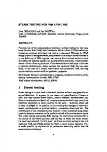
characteristics of a large-scale bridge deck by performing tests on smaller components or assemblies that go into its fabrication. The first and third layers from the top of the sample consisted of thirty-two 304.8 mm (1 ft) long GFRP tubes in both layers having the same cross-section as the single tubes. The second and the fourth layers from the top of the sample consisted of four GFRP tubes in each layer, similar in dimensions to the single tubes described before. The assembly of the tubes and the overall dimension of the sample is shown in Figure 1. Hysol’s 9460 epoxy was used as the adhesive. The full structure was assembled in two steps. The bottom most layer was assembled first. Four 2.44 m (8 ft) GFRP tubes were scuff sanded and washed with acetone. A thin layer of adhesive was applied to them and they were held together using bar clamps to bond them together. The second layer from the bottom consisting of thirty-two 304.8 mm (1 ft) long tubes was added to the top of the first layer. The first tube was c-clamped to the lower layer and the next tube was c-clamped to this tube. As the tubes were added the c-clamp was moved to the next tube. A piece of plywood was placed on top of this layer of tubes and several heavy weights were placed over it. Another similar two-layer structure was assembled separately using the same technique and both the assemblies were allowed to cure overnight. Both the two-layer structures were bonded together using a thin layer of adhesive to form a single four-layered structure with dimensions of 2.44 m x 304.8 mm x 304.8 mm (8 ft x 1 ft x 1 ft). The whole assembly was cured for 72 hours prior to testing.
8
Prakash Kumar, K. Chandrashekhara and Antonio Nanni, “Testing and Evaluation of Components for a Composite Bridge Deck,” Journal of Reinforced Plastic s and Composites, March 2001.
The first and the third layers from the top were mainly responsible for distributing the load to the second and fourth layers that were the main load-bearing members. 4. EXPERIMENTAL SETUP AND INSTRUMENTATION The single tubes and the double tube assemblies were tested in four-point bending configuration, as shown in Figures 2 and 3, while the four-layered tube assembly was tested in three-point bending configuration, as show in Figure 4. The samples were tested in simply supported boundary conditions and were placed on rollers on both the ends spaced at a distance of 2.13 mm (7 ft) so that the sample extended 152.4 mm (6 in) beyond the support rollers at each end. To alleviate the effects of surface imperfections and assure uniform reaction forces, a piece of plywood was placed between the steel plates and the bottom surface of the samples.
Load was applied using a Baldwin
Universal Testing machine with the centers of sample and the loading machine aligned together. For the four-point bending test, the two points of loading were 152.4 mm (6 in) on both sides of the center of the sample. A 12.7 mm (0.5 in) thick steel plate was placed under each point of loading so as to distribute the load over a wider area of the sample. A 89 kN (20,000 lb) load cell was used to measure the load. In the three-point bending test on the four-layered tube assembly, the center load was imposed through a 20.3 mm (0.8 in) thick 304.8 mm (1 ft) square steel plate with a plywood pad between the sample top surface and the steel plate. A 222 kN (50,000 lb) load cell was used to measure the load for this case.
The instrumentation of the samples consisted of LVDTs (Linear variable differential transformers) to measure displacement and 6 mm (0.24 in) long 120 ohms electrical resistance strain gages for strain measurement. Three LVDTs were attached to each of the samples, two at the points of support and one at the mid-span, to measure the linear deflection. Two strain gages were attached to each of the samples to measure the strain developed. In case of single tube and double tube assembly, the strain gages were mounted at the center on both the tension and compression faces of the tube while in the case of the four-layered tube assembly, both the strain gages were attached to the tension
9
Prakash Kumar, K. Chandrashekhara and Antonio Nanni, “Testing and Evaluation of Components for a Composite Bridge Deck,” Journal of Reinforced Plastic s and Composites, March 2001.
face of the structure. The center of the compression face of the four-layered sample was used for loading and so no strain gage could be mounted on it. All strain gages were mounted on the surface of the fiberglass material. 5. TEST PROCEDURE The loading of the single tube was done in cycles of 6.68 kN (1,500 lb). For the double tube the loading cycle was increased to 13.35 kN (3,000 lb) while for the fourlayered tube assembly the loading cycle was 22.25 kN (5,000 lb). The cyclic loading of the specimen was done so as to evaluate damage accumulation, stability and any residual deflection, strain or any energy loss occurring in it due to the applied load. Significant events such as cracking sounds, distortion of the shape of the tubes and breaking of the joints or fibers were observed whenever possible. The load was gradually increased and the rate of loading and unloading was kept constant during all the tests. Data sampling frequency was sufficiently high to capture all the important events in the course of the test.
All the three specimens were tested to failure. The single tube took a load of 24.12 kN (5,420 lb), the double tube assembly took 62.30 kN (14,000 lb) while the fourlayered tube assembly took a load of 182.76 kN (41,070 lb) before failure. 6. FAILURE MODE Static tests were conducted on the samples to determine ultimate static strength and failure progression.
All the tests conducted were load controlled.
Composite
materials exhibit very complex failure mechanisms under static loading because of their anisotropic nature. Failure may involve multiple damage modes that can be observed as fiber breakage, matrix cracking, interfacial debonding, delamination, or a combination of these failures. The ultimate bending strength of pultruded composite beams is limited by various failure mechanisms. Local buckling of the thin walls precipitates most failure modes. It initiates a failure mode that eventually results in material degradation and total failure of the beam.
10
Prakash Kumar, K. Chandrashekhara and Antonio Nanni, “Testing and Evaluation of Components for a Composite Bridge Deck,” Journal of Reinforced Plastic s and Composites, March 2001.
In the case of single tube and double tube assembly, the loading was done in cycles as specified before until the point of failure. The failure occurred at one of the points of loading and distinct cracks appeared on the top surface and sides of the tubes. In both the cases, local buckling of the compression flange initiated the failure resulting in the failure of the sample. Cracks developed at the web-flange junction due to the buckling leading to separation of web and flange. This was followed by bending of the web about its weak axis developing cracks at the middle of the web. A delamination crack of the compression flange was observed. The flange cracks then propagated into the web leading to the final failure of the section.
The failure mode of the four-layered tube assembly was very different than those of the other two samples. As the load was applied, this structure exhibited progressive damage accumulation with the increase in load, indicated by the cracking sounds observed. The first few cracking sounds started at about 89 kN (20,000 lb). The origin of the sound could not be determined. However, based on the observed ultimate load, the most likely cause of the sounds was breaking of the adhesive bonding between the tubes of the assembly. The micro fracture continued to occur with increasing loads, however, they were reduced, or did not continue during cyclic loading, indicating stability. At about 111.25 kN (25,000 lb) some deformations in the shape of the tubes of the first and third layers were observed. The tubes in these layers were acted upon by compressive forces due to the loading.
These tubes, laid down transverse to the direction of traffic,
started to bend away from the center changing their shape from square to a parallelogram. As the load was increased to 133.50 kN (30,000 lb), cracks appeared along the corners of few of the tubes in the first and third layers due to the twisting motion. Breaking of fibers and delamination was also was observed in these layers. The noise coming from the sample had increased considerably. At a load of 182.76 kN (41,070 lb), a few of the small tubes from the first layer popped out of the structure due to the compressive load on them. It was observed that several tubes in the first and the third layers had cracked and had been bent away from the center towards one of the sides. No damage was observed in the second and fourth layers, which were the main load bearing members. The mode
11
Prakash Kumar, K. Chandrashekhara and Antonio Nanni, “Testing and Evaluation of Components for a Composite Bridge Deck,” Journal of Reinforced Plastic s and Composites, March 2001.
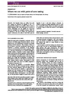
of failure observed was transverse shear failure resulting in the delaminations and cracking of fibers along the edges of the GFRP pultruded tubes. Figure 5 shows the bending and distortion of the GFRP tubes under bending and also the sample after failure due to the popping out of tubes from the top layer. 7. TEST RESULTS The test results are presented separately for deflection and strain.
Key
information is presented and discussed in the following sections. In general, data for all three samples have been presented together for each type of measurement as opposed to showing all the data for each one of them in succession.
7.1. DEFLECTION
The load-deflection plots for the three specimens show the complete curves, and indicate gradual stiffness degradation with increasing load levels. In the case of single tube and double tube assembly, the observed behavior is essentially linear elastic up to failure. In the case of the four-layered tube assembly, it shows a linear elastic behavior up to a load of about 89 kN (20,000 lb) beyond which the structure exhibits distinct nonlinear characteristics. The failure of the single GFRP tube occurred at a load of 24.12 kN (5,420 lb) and the total deflection of the tube at this point was 139 mm (5.47 in). Figure 6 (a) shows the graph of deflection plotted against the applied load for the single tube test. The double tube assembly took a load of 62.30 kN (14,000 lb) and had a maximum deflection of 63.3 mm (2.49 in). Figure 7 (a) shows the graph of deflection plotted against applied load for this specimen. The maximum load taken by the four-layered tube before failure was 182.45 kN (41,000 lb). The deflection at this load was 81.3 mm (3.2 in). The assembly showed non-linear characteristics beyond 89 kN (20,000 lb) and all the data up to and past this load is taken into consideration. Figure 8 (a) shows the graph of deflection plotted against the applied load in the elastic region for this specimen. The stiffness degradation of the three specimens with increasing load appears to be caused by damage accumulation, which is indicated by the small load drop in the loading curves. 12
Prakash Kumar, K. Chandrashekhara and Antonio Nanni, “Testing and Evaluation of Components for a Composite Bridge Deck,” Journal of Reinforced Plastic s and Composites, March 2001.
7.2. STRAIN
Two strain gages were attached to each of the specimens to measure the surface strains developed. In the case of single tube and double tube assembly, the strain gages are connected to the center of the top and bottom surfaces to measure the compressive and tensile strains. In the case of four-layered tube assembly, both strain gages were connected at the bottom of the structure as the center of the compressive face was used for loading. Figures 6 (b), 7 (b) and 8 (b) show the graphs of strain plotted against the applied load in the case of a single tube, double tube and four-layered tube assembly, respectively. The graph for the four-layered tube assembly is shown only up to the linear elastic region. In general the strain results are excellent and indicate good symmetry about the centerline.
The data obtained from the deflection and strain reading for the single tube and double tube assembly were used for calculating the flexural rigidity or Young’s modulus, E, of the tube.
In the case of a single tube, the Young’s modulus obtained using
deflection criteria was 24.27 GPa (3,520 ksi), using compressive strain its value was 22.96 GPa (3,330 ksi), while tensile strain gave a value of 26.13 GPa (3,790 ksi). For the double tube assembly, the Young’s modulus obtained using deflection criteria was 24.13 GPa (3,500 ksi), using compressive strain its value was 22.48 GPa (3,260 ksi) and that obtained using tensile strain was 25.37 GPa (3,680 ksi). The experimental results showed that the composite beams can experience large deformations and strains with the material remaining in the linear region. In the case of the double tube assembly it also showed that the assembly behaves as a single unit and that the bonding between the two tubes was perfect. Investigation of the bending behavior of GFRP tubes shows that the bending stiffness is low compared to that of steel sections of the same shape. It also indicates that shear deformation effects are significant. This is a consequence of the relatively low modulus of elasticity of the glass fibers, as compared to steel, and the low shear modulus of the resin. Most significantly, due to the large elongation to failure allowed by both the fibers (4.0%) and the resin (4.5%), the composite material remains linearly elastic for
13
Prakash Kumar, K. Chandrashekhara and Antonio Nanni, “Testing and Evaluation of Components for a Composite Bridge Deck,” Journal of Reinforced Plastic s and Composites, March 2001.
large deflections and strains (Fu et al. (1990). As a consequence of local buckling, large strains are induced during post-buckling. These large strains ultimately lead to the failure of the material and subsequent total failure of the member. 8. CONCLUSIONS The testing and analysis undertaken on the square GFRP composite tubes and their assemblies indicates in general that composite materials and similar types of assemblies made out of them can be used as an efficient structural component in a number of civil infrastructure applications such as building bridges. The tests demonstrate that readily available pultruded FRP tubes, assembled together in the configuration shown before, meet the strength requirement and the other necessary performance criteria. The endurance of GFRP box beams subjected to static flexure loadings and the consequent failure are the principal measures of structural performance as established through this project. Following are the conclusions based on the test: 1. The deflection and strain graphs for the single tube and double tube assembly shows linear elastic bending and shear behavior up to failure. In case of fourlayered tube assembly, the deflection and strain graphs are linear elastic for a considerable amount of load beyond which it shows distinct non-linear characteristics.
The deflections and strains in the elastic region are very
symmetric. 2. Damages accumulate gradually as the load increases, as indicated by cracking, which is reflected in the deflection and strain graphs.
Ultimate failure is
catastrophic breaking of the fibers on the surface of loading and the sides of the tubes or popping out of the tubes from the assembly. 3. Web-flange junction was observed to be the principle location of failure. Therefore it is suggested that the performance of the beams can be enhanced by having fiber continuity between the flange and the web of the GFRP pultruded tubes. 4. Finite element analysis is very useful to determine the effect of a number of geometric and material parameters, as well as to validate simple analytical models and design procedures. More complete and accurate analysis can be done if the 14
Prakash Kumar, K. Chandrashekhara and Antonio Nanni, “Testing and Evaluation of Components for a Composite Bridge Deck,” Journal of Reinforced Plastic s and Composites, March 2001.
failure loads can be predicted computationally, and if techniques could be developed to modify the failure mode towards more ductile behavior. 5. Carbon fiber reinforced polymer (CFRP) tubes should be used in the main load bearing layers so as to increase the stiffness of the structure even further. 6. The design can be further refined by reducing the number of tubes from the layers which only take a small portion of the complete load of the structure leading to the reduction in the material and the overall cost. 7. The tube-to-tube joining systems should be designed and studied both experimentally and computationally because the strength and performance of the structure also depends to a great extend on how efficiently the tubes have been assembled. From the above conclusions and recommendations, we can summarize that the present research on hollow square GFRP tubes and their assemblies holds significant promise in the building of composite bridge deck and for other civil infrastructure applications.
The data obtained from the tests will allow the bridge designers to
understand how FRP composite materials perform under actual loading conditions and will result in increased application of composites in highway bridges and other infrastructure uses. 9. ACKNOWLEDGEMENTS The Missouri Department of Transportation, National Science Foundation – CRCD
program,
Lemay
Center
for
Composites
Technology,
and
University
Transportation Center of University of Missouri at Rolla supported this work. The authors would like to thank Mr. John Unser of Composite Products Inc. for providing the test samples. 10. REFERENCES Liskey, K. (1991). “Structural Applications of Pultruded Composite Products”, Proceedings of Specialty Conference on Advanced Composite Materials in
15
Prakash Kumar, K. Chandrashekhara and Antonio Nanni, “Testing and Evaluation of Components for a Composite Bridge Deck,” Journal of Reinforced Plastic s and Composites, March 2001.
Civil Engineering Structures, Las Vegas, NV, January 31 & February 1, ASCE, New York, N.Y., pp. 182-193. Karbhari, V.M., Seible, F., Heigemier, G. A. and Zhao, L. (1997). “Fiber Reinforced Composite Decks for Infrastructure Renewal - Results and Issues”, Proceedings of International Composites Expo, Session 3-C, pp. 1-6. Aref, A. J. and Parsons, I. D. (1996). “Design and Analysis Procedures for a Novel Fiber Reinforced Plastic Bridge Deck”, Advanced Composite Materials in Bridges and Structures, CSCE, Montreal, Quebec, Canada, pp. 743-750. Zureick, A. H., Shih, B., and Munley, E. (1995). “Fiber-Reinforced Polymeric Bridge Decks”, Structural Engineering Review, Vol.7, No.3, pp. 257-266. Ballinger, C. A. (1990). “Structural FRP composites-Civil Engineering’s Material of the Future?”, Civil Engineering, ASCE, 60(7), pp. 63-65. Bank, L. C., (1989). “Properties of Pultruded Fiber Reinforced Plastic Structural Members”, Transportation Research Record 1223, Transportation Research Board, Washington D.C., pp. 117-124. Nagraj, V. and Gangarao, H. V. S. (1993). “ Characterization of GFRP Pultruded Box Beams Under Static and Fatigue Loads”, SAMPE Quarterly (Journal of Advanced Materials), Vol.24, No.4, pp. 3-9. Davalos, J. F., and Qiao, P. (1997). “Analytical and Experimental Study of Lateral and Distortional Buckling of FRP Wide-Flange Beams”, Journal of Composites for Construction, Vol. 1, No. 4, pp. 150-159. Sotiropoulos, S. N., Gangarao, H. V. S., and Allison, R. W. (1994). “Structural Efficiency of Pultruded FRP Bolted and Adhesive Connections”, Proceedings of 49th
16
Prakash Kumar, K. Chandrashekhara and Antonio Nanni, “Testing and Evaluation of Components for a Composite Bridge Deck,” Journal of Reinforced Plastic s and Composites, March 2001.
Annual Conference, Composite Institute, The Society of Plastics Industry Inc., Cincinnati, Ohio, SPI/Composite Institute, New York, N.Y. Barbero, E. J., Fu, S. H. and Raftoyiannis, I. (1991). “Ultimate Bending Strength of Composite Beams”, Journal of Materials in Civil Engineering, Vol.3, No.4, November, pp. 292-306. Fisher, S., Roman, I., Harel, H., Marom, G., and Wagner, H. D. (1981). “Simultaneous Determination of Shear and Young’s Moduli in Composites”, Journal of Testing and Evaluation, Vol.9, No.5, September, pp. 303-307. Nagraj, V., and Gangarao, H. V. S. (1997). “Static Behavior of Pultruded GFRP Beams”, Journal of Composites for Construction, Vol.1, No.3, August, pp. 120-129. Agarwal, B. D. and Broutman, L. J. (1990), “Analysis and Performance of Fiber Composites”, John Wiley & Sons, Inc. American Association of State Highway and Transportation Officials. (1996). “Standard Specifications for Highway Bridges”, AASHTO, Washington D.C., Sixteenth Edition. Fu, S. H., Spyrakos, C., Prucz, J., and Barbero, E. J. (1990). “Structural Performance of Plastic I-Beams”, Proceedings of Eighth Annual Structures Congress, ASCE, pp. 507-508.
LIST OF FIGURES Figure 1: Four-layered GFRP tube assembly. Figure 2: A single GFRP tube immediately (a) before and (b) after failure. Figure 3: A double GFRP tube assembly immediately (a) before and (b) after failure.
17
Prakash Kumar, K. Chandrashekhara and Antonio Nanni, “Testing and Evaluation of Components for a Composite Bridge Deck,” Journal of Reinforced Plastic s and Composites, March 2001.
Figure 4: A four-layered GFRP tube assembly under loading (a) experimental setup and (b) deflection under loading. Figure 5: Four-layered tube assembly (a) under bending, showing distortion of the GFRP tubes, and (b) after failure. Figure 6: Graphs of (a) deflection and (b) strain in a single GFRP tube test plotted against applied load. Figure 7: Graphs of (a) deflection and (b) strain in a double tube assembly test plotted against applied load Figure 8: Graphs of (a) deflection and (b) strain in a four-layered tube assembly test plotted against applied load.
18
Prakash Kumar, K. Chandrashekhara and Antonio Nanni, “Testing and Evaluation of Components for a Composite Bridge Deck,” Journal of Reinforced Plastic s and Composites, March 2001.
Note: All dimensions are in inches,1 in = 25.4 mm Figure 1: Four-layered GFRP tube assembly
19
Prakash Kumar, K. Chandrashekhara and Antonio Nanni, “Testing and Evaluation of Components for a Composite Bridge Deck,” Journal of Reinforced Plastic s and Composites, March 2001.
(a)
(b) Figure 2: A single GFRP tube immediately (a) before and (b) after failure.
20
Prakash Kumar, K. Chandrashekhara and Antonio Nanni, “Testing and Evaluation of Components for a Composite Bridge Deck,” Journal of Reinforced Plastic s and Composites, March 2001.
(a)
(b) Figure 3: A double GFRP tube assembly immediately (a) before and (b) after failure.
21
Prakash Kumar, K. Chandrashekhara and Antonio Nanni, “Testing and Evaluation of Components for a Composite Bridge Deck,” Journal of Reinforced Plastic s and Composites, March 2001.
(a)
(b) Figure 4: A four-layered GFRP tube assembly under loading (a) experimental setup and (b) deflection under loading.
22
Prakash Kumar, K. Chandrashekhara and Antonio Nanni, “Testing and Evaluation of Components for a Composite Bridge Deck,” Journal of Reinforced Plastic s and Composites, March 2001.
(a)
(b) Figure 5: Four-layered tube assembly (a) under bending, showing distortion of the GFRP tubes, and (b) after failure.
23
Prakash Kumar, K. Chandrashekhara and Antonio Nanni, “Testing and Evaluation of Components for a Composite Bridge Deck,” Journal of Reinforced Plastic s and Composites, March 2001.
6000 5000 4000 3000 2000 1000 0 0
1000
2000 3000 4000 Deflection (milli in)
5000
(a) Load Vs. Deflection
6000 5000 4000 3000 2000 Compression Tension
1000 0 0
2000
4000
6000 8000 Micro strain
10000
12000
(b) Load Vs. Strain Note: 1 in = 25.4 mm, 1 lb = 4.45 N Figure 6: Graphs of (a) deflection and (b) strain in a single GFRP tube test plotted against applied load.
24
Prakash Kumar, K. Chandrashekhara and Antonio Nanni, “Testing and Evaluation of Components for a Composite Bridge Deck,” Journal of Reinforced Plastic s and Composites, March 2001.
16000 14000 12000 10000 8000 6000 4000 2000 0 0
500
1000
1500
2000
2500
Deflection (milli in)
(a) Load Vs. Deflection 16000 14000 12000 10000 8000 6000 4000
Compression Tension
2000 0 0
2000
4000
6000 Micro strain
8000
10000
12000
(b) Load Vs. Strain Note: 1 in = 25.4 mm, 1 lb = 4.45 N Figure 7: Graphs of (a) deflection and (b) strain in a double tube assembly test plotted against applied load.
25
Prakash Kumar, K. Chandrashekhara and Antonio Nanni, “Testing and Evaluation of Components for a Composite Bridge Deck,” Journal of Reinforced Plastic s and Composites, March 2001.
20
15
10
5
0 0
100
200
300
400
500
600
700
800
900
Deflection (milli in) (a) Load Vs. Deflection
20
15
10
5
0 0
500
1000
1500
2000
2500
3000
Micro strain
(b) Load Vs. Strain Note: 1 in = 25.4 mm; 1 kip = 4.45 kN Figure 8: Graphs of (a) deflection and (b) strain in a four-layered tube assembly test plotted against applied load.
26